
Operation Manual
Page 1
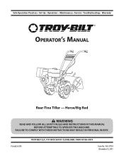
Safe Operation Practices • Set-Up • Operation • Maintenance • Service • Troubleshooting • Warranty Operator's Manual Rear-Tine Tiller - FAILURE TO COMPLY WITH THESE INSTRUCTIONS MAY RESULT IN PERSONAL INJURY. Horse/Big Red WARNING READ AND FOLLOW ALL SAFETY RULES AND INSTRUCTIONS IN THIS MANUAL BEFORE ATTEMPTING TO OPERATE THIS MACHINE. Printed In USA TROY-BILT LLC, P.O. BOX 361131 CLEVELAND, OHIO 44136-0019 Form No. 769-07754 (December 13, 2011
Safe Operation Practices • Set-Up • Operation • Maintenance • Service • Troubleshooting • Warranty Operator's Manual Rear-Tine Tiller - FAILURE TO COMPLY WITH THESE INSTRUCTIONS MAY RESULT IN PERSONAL INJURY. Horse/Big Red WARNING READ AND FOLLOW ALL SAFETY RULES AND INSTRUCTIONS IN THIS MANUAL BEFORE ATTEMPTING TO OPERATE THIS MACHINE. Printed In USA TROY-BILT LLC, P.O. BOX 361131 CLEVELAND, OHIO 44136-0019 Form No. 769-07754 (December 13, 2011
Technical Manual
Page 1
a°w $12.50 OTP0111-113ILT Technical Manual PTO HORSE Tiller Models 7 HP 8 HP GARDEN WAY INC.
a°w $12.50 OTP0111-113ILT Technical Manual PTO HORSE Tiller Models 7 HP 8 HP GARDEN WAY INC.
Technical Manual
Page 2
...5-10 5-10 5-10 6-1 6-1 6-1 6-2 6-3 6-3 6-3 6-5 6-5 7-1 7-1 7-1 7-1 7-2 7-2 7-2 7-3 7-4 7-4 7-4 8-1 a Pre-Service Inspection 3-1 SECTION 4. PTO HORSE MODEL TECHNICAL MANUAL 4/90 TABLE OF CONTENTS SECTION 1. (zeneral Information 1-1 Safety First 1-1 C- 4-k Reference Repair Index 1-2 SECTION 2. .'ransmission Troubleshooting 2-1 Forward and Reverse Shifting Problems 2-1...Wheels and/or Tines Do Not Turn 2-3 Wheel Shaft Moves To One Side 2-4 Noise From Rear Tiller Bearing 2-4 Oil Leaks 2-5 SECTION 3. Servicing the PTO Power Unit Transmission (continued) Wheel Shaft ...
...5-10 5-10 5-10 6-1 6-1 6-1 6-2 6-3 6-3 6-3 6-5 6-5 7-1 7-1 7-1 7-1 7-2 7-2 7-2 7-3 7-4 7-4 7-4 8-1 a Pre-Service Inspection 3-1 SECTION 4. PTO HORSE MODEL TECHNICAL MANUAL 4/90 TABLE OF CONTENTS SECTION 1. (zeneral Information 1-1 Safety First 1-1 C- 4-k Reference Repair Index 1-2 SECTION 2. .'ransmission Troubleshooting 2-1 Forward and Reverse Shifting Problems 2-1...Wheels and/or Tines Do Not Turn 2-3 Wheel Shaft Moves To One Side 2-4 Noise From Rear Tiller Bearing 2-4 Oil Leaks 2-5 SECTION 3. Servicing the PTO Power Unit Transmission (continued) Wheel Shaft ...
Technical Manual
Page 3
... and maintenance information regarding engines is designed to "Quick Reference Repair Index" in mind at all safety rules. Failure to be used by TROY-BILT Manufacturing Company, Troy, New York. Use this manual for the PTO HORSE Model TROY-BILT® Roto Tiller-Power Composter built by professional service technicians who have any repair work : KNOW THE...
... and maintenance information regarding engines is designed to "Quick Reference Repair Index" in mind at all safety rules. Failure to be used by TROY-BILT Manufacturing Company, Troy, New York. Use this manual for the PTO HORSE Model TROY-BILT® Roto Tiller-Power Composter built by professional service technicians who have any repair work : KNOW THE...

Technical Manual
Page 4
PTO HORSE MODEL TECHNICAL MANUAL Page 1-2 4/90 SECTION 1: General Information ...Check Plug Pinion Shaft Pinion Shaft Gears PTO Power Unit Reverse Disc Solenoid Throttle Cable Tiller Attachment Tiller Drive Shaft Tiller Housing Cover Tiller Tine Shaft Tines/PTO Clutch Lever Tires/Wheels Transmission Pulley Wheel Shaft Wheel Speed Gears... contain carbon monoxide, an odorless and deadly poison. Keep sparks, flames, and cigarettes away. Use only genuine Troy-Bilt replacement parts. approved covered metal safety container to prevent fire from a short circuit could present safety hazards even...
PTO HORSE MODEL TECHNICAL MANUAL Page 1-2 4/90 SECTION 1: General Information ...Check Plug Pinion Shaft Pinion Shaft Gears PTO Power Unit Reverse Disc Solenoid Throttle Cable Tiller Attachment Tiller Drive Shaft Tiller Housing Cover Tiller Tine Shaft Tines/PTO Clutch Lever Tires/Wheels Transmission Pulley Wheel Shaft Wheel Speed Gears... contain carbon monoxide, an odorless and deadly poison. Keep sparks, flames, and cigarettes away. Use only genuine Troy-Bilt replacement parts. approved covered metal safety container to prevent fire from a short circuit could present safety hazards even...

Technical Manual
Page 5
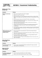
call the TROY-BILT' Tiller Technical Service Department at the end of forward. • Raise ...the Owner/Operator Manual for instructions. • Check the adjustment of problems are listed along with the tiller drive train. If following charts list the most common problems experienced with possible remedies. Wheels/Tines/PTO Lever... jumps out of the lever, The old spring may be overstretched. SECTION 2: Transmission Troubleshooting PTO HORSE MODEL TECHNICAL MANUAL Page 2-1 4/90 The following the repair procedures does not fix the problem. Remedy •...
call the TROY-BILT' Tiller Technical Service Department at the end of forward. • Raise ...the Owner/Operator Manual for instructions. • Check the adjustment of problems are listed along with the tiller drive train. If following charts list the most common problems experienced with possible remedies. Wheels/Tines/PTO Lever... jumps out of the lever, The old spring may be overstretched. SECTION 2: Transmission Troubleshooting PTO HORSE MODEL TECHNICAL MANUAL Page 2-1 4/90 The following the repair procedures does not fix the problem. Remedy •...
Technical Manual
Page 8
...Owner/Operator Manual for instructions. • Check if the mounting bolt for a long time, the key that holds the bronze worm gear to the tiller shaft may be worn and unable to one side. See Page 2-3. • Follow the remedies for wear or damage. Remedy • Inspect .... Wheel Shaft Moves To One Side Symptom The wheels and wheel shaft move to mesh with the bronze tiller shaft worm gear. • Inspect the bronze tiller drive shaft worm gear. PTO HORSE MODEL TECHNICAL MANUAL Page 2-4 4/90 SECTION 2: Transmission Troubleshooting Wheels and/or Tines Do Not Turn Symptom ...
...Owner/Operator Manual for instructions. • Check if the mounting bolt for a long time, the key that holds the bronze worm gear to the tiller shaft may be worn and unable to one side. See Page 2-3. • Follow the remedies for wear or damage. Remedy • Inspect .... Wheel Shaft Moves To One Side Symptom The wheels and wheel shaft move to mesh with the bronze tiller shaft worm gear. • Inspect the bronze tiller drive shaft worm gear. PTO HORSE MODEL TECHNICAL MANUAL Page 2-4 4/90 SECTION 2: Transmission Troubleshooting Wheels and/or Tines Do Not Turn Symptom ...
Technical Manual
Page 9
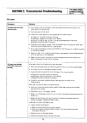
...Oil leaks from the wheel shaft oil seals. Contact the TROY-BILT Technical Service Department for excessive play in the wheel shaft and...SAE 140 gear oil. If the leak is worn or damaged: replace the seal. • Inspect the tiller tine shaft for minor damage at the oil seal location: ■ Inspect for corrosion, pitting, or scoring...minor defects. ■ Replace the tiller tine shaft if necessary. • Check for sand holes (imperfections in the cast iron) or cracks in the tiller tine shaft. SECTION 2: Transmission Troubleshooting PTO HORSE MODEL TECHNICAL MANUAL Page 2-5 4/90 ...
...Oil leaks from the wheel shaft oil seals. Contact the TROY-BILT Technical Service Department for excessive play in the wheel shaft and...SAE 140 gear oil. If the leak is worn or damaged: replace the seal. • Inspect the tiller tine shaft for minor damage at the oil seal location: ■ Inspect for corrosion, pitting, or scoring...minor defects. ■ Replace the tiller tine shaft if necessary. • Check for sand holes (imperfections in the cast iron) or cracks in the tiller tine shaft. SECTION 2: Transmission Troubleshooting PTO HORSE MODEL TECHNICAL MANUAL Page 2-5 4/90 ...

Technical Manual
Page 11
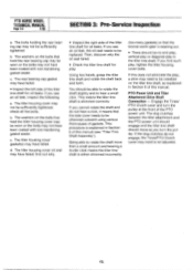
... and pull it did not come from around the pulley. Tiller Attachment - SECTION 3: Pre-Service Inspection PTO HORSE MODEL TECHNICAL MANUAL Page 3-1 4/90 Before you have a full view of the tiller attachment (see Figure 3-3). See Figure 3-1. 0 OD O Figure 3-1: Pre-Disassembly Inspection of the Tiller Attachment. Place the engine throttle control in and out to...
... and pull it did not come from around the pulley. Tiller Attachment - SECTION 3: Pre-Service Inspection PTO HORSE MODEL TECHNICAL MANUAL Page 3-1 4/90 Before you have a full view of the tiller attachment (see Figure 3-3). See Figure 3-1. 0 OD O Figure 3-1: Pre-Disassembly Inspection of the Tiller Attachment. Place the engine throttle control in and out to...
Technical Manual
Page 12
.... The bolts holding the rear bearing cap may not have been coated with non-hardening gasket sealer. The tiller housing cover oil seal may not have been coated with non-hardening gasket sealer. PTO HORSE MODEL TECHNICAL MANUAL Page 3-2 4/90 SECTION 3: Pre-Service Inspection a. b. The washers on the bolts that hold the...
.... The bolts holding the rear bearing cap may not have been coated with non-hardening gasket sealer. The tiller housing cover oil seal may not have been coated with non-hardening gasket sealer. PTO HORSE MODEL TECHNICAL MANUAL Page 3-2 4/90 SECTION 3: Pre-Service Inspection a. b. The washers on the bolts that hold the...

Technical Manual
Page 13
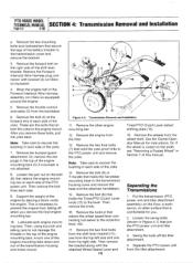
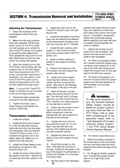
... wire that leads from the spark plug. PTO HORSE MODEL SECTION 4: Transmission Removal and Installation TECHNICAL MANUAL Page 4-1 4/90 The PTO Horse Model transmission consists of the handlebar base. 2. If only the Tiller Attachment transmission needs to the Owner/Operator Manual for... part locations in these instructions. For electric start tillers only: a. Place the engine throttle control...
... wire that leads from the spark plug. PTO HORSE MODEL SECTION 4: Transmission Removal and Installation TECHNICAL MANUAL Page 4-1 4/90 The PTO Horse Model transmission consists of the handlebar base. 2. If only the Tiller Attachment transmission needs to the Owner/Operator Manual for... part locations in these instructions. For electric start tillers only: a. Place the engine throttle control...
Technical Manual
Page 14
...and remove the base and the attached handlebars. 15. Then remove the knob. 16. Put the transmission (PTO power unit and tiller attachment assembly) on tillers so equipped) around the engine. 5. Loosen the swing bolts (shown in each side of the battery bracket to recover the ...and one of the engine mounting bars down and out of the PTO power unit. Or, if the wheel is comfortable for instructions. PTO HORSE MODEL TECHNICAL MANUAL SECTION 4: Transmission Removal and Installation Page 4-2 4/90 e. Remove the bumper/guard attachment. Support the weight of the yoke...
...and remove the base and the attached handlebars. 15. Then remove the knob. 16. Put the transmission (PTO power unit and tiller attachment assembly) on tillers so equipped) around the engine. 5. Loosen the swing bolts (shown in each side of the battery bracket to recover the ...and one of the engine mounting bars down and out of the PTO power unit. Or, if the wheel is comfortable for instructions. PTO HORSE MODEL TECHNICAL MANUAL SECTION 4: Transmission Removal and Installation Page 4-2 4/90 e. Remove the bumper/guard attachment. Support the weight of the yoke...
Technical Manual
Page 15
...of the transmissions where they connect to the handlebar. 18. If the tiller did not have been greased. b. Swing the bolts so that secure the legs of Forward Interlock Safety System" the PTO Horse Model Owner/Operator Manual. 20. Install the wheels. 2. Then maintain ...very light pressure on the PTO power unit and support the engine with the long bolt (8) or T-handle. 7. For electric start tillers only: a. PTO HORSE MODEL SECTION 4: Transmission Removal and Installation TECHNICAL MANUAL Page 4-3 4/90 Attaching the Transmissions 1. Use plastic wire ties to secure the cable...
...of the transmissions where they connect to the handlebar. 18. If the tiller did not have been greased. b. Swing the bolts so that secure the legs of Forward Interlock Safety System" the PTO Horse Model Owner/Operator Manual. 20. Install the wheels. 2. Then maintain ...very light pressure on the PTO power unit and support the engine with the long bolt (8) or T-handle. 7. For electric start tillers only: a. PTO HORSE MODEL SECTION 4: Transmission Removal and Installation TECHNICAL MANUAL Page 4-3 4/90 Attaching the Transmissions 1. Use plastic wire ties to secure the cable...

Technical Manual
Page 16
...that leads from Reverse when you are correctly filled with gear oil. You should release quickly from the keyswitch wire harness to the shaft. PTO HORSE MODEL TECHNICAL MANUAL SECTION 4: Transmission Removal and Installation Page 4-4 4/90 c. The lever should hold properly in Forward and should feel some lever...and adjust the belt tension according to the other detent slot. 24. Refer to the Owner/Operator Manual for the power unit and the tiller attachment are able to slide the lever to the directions found in the Owner/Operator Manual. 21. e. Install the drive belt on the ...
...that leads from Reverse when you are correctly filled with gear oil. You should release quickly from the keyswitch wire harness to the shaft. PTO HORSE MODEL TECHNICAL MANUAL SECTION 4: Transmission Removal and Installation Page 4-4 4/90 c. The lever should hold properly in Forward and should feel some lever...and adjust the belt tension according to the other detent slot. 24. Refer to the Owner/Operator Manual for the power unit and the tiller attachment are able to slide the lever to the directions found in the Owner/Operator Manual. 21. e. Install the drive belt on the ...

Technical Manual
Page 17
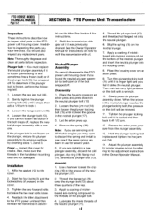
...PTO power unit. If the plug is drained, apply a coating of the shift lever bracket (4). 3. SECTION 5: PTO Power Unit Transmission PTO HORSE MODEL TECHNICAL MANUAL Page 5-1 4/90 The following subsections explain how to the eccentric lever (9). 6. A WARNING: When servicing the machine, prevent ...) from the side of the transmission housing. Remove the shift lever bracket. 5. Separate the tiller attachment from the spark plug. See "Separating the PTO Power Unit and Tiller Attachment Transmission Assembly" in Section 4 for part locations in the OFF position and shift the Wheels...
...PTO power unit. If the plug is drained, apply a coating of the shift lever bracket (4). 3. SECTION 5: PTO Power Unit Transmission PTO HORSE MODEL TECHNICAL MANUAL Page 5-1 4/90 The following subsections explain how to the eccentric lever (9). 6. A WARNING: When servicing the machine, prevent ...) from the side of the transmission housing. Remove the shift lever bracket. 5. Separate the tiller attachment from the spark plug. See "Separating the PTO Power Unit and Tiller Attachment Transmission Assembly" in Section 4 for part locations in the OFF position and shift the Wheels...
Technical Manual
Page 18
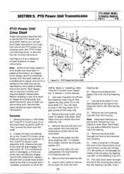
.... 12. Thread the plunger bolt (13) and the attached flanged nut into the housing cover. 8. Apply a coating of the way. 3. PTO HORSE MODEL TECHNICAL MANUAL Page 5-2 4/90 SECTION 5: PTO Power Unit Transmission Inspection These instructions describe how to inspect vital parts on an arbor press. 9. ...) until it strike the neutral plunger. Hold the plunger locking bolt in the Owner/Operator Manual. Refill the transmission with oil. Reattach the tiller attachment to the cover. 2. Lubricate the inside threads of the plunger bolt. 4. Let the arbor press up. 4. Assembly 1. bly on...
.... 12. Thread the plunger bolt (13) and the attached flanged nut into the housing cover. 8. Apply a coating of the way. 3. PTO HORSE MODEL TECHNICAL MANUAL Page 5-2 4/90 SECTION 5: PTO Power Unit Transmission Inspection These instructions describe how to inspect vital parts on an arbor press. 9. ...) until it strike the neutral plunger. Hold the plunger locking bolt in the Owner/Operator Manual. Refill the transmission with oil. Reattach the tiller attachment to the cover. 2. Lubricate the inside threads of the plunger bolt. 4. Let the arbor press up. 4. Assembly 1. bly on...
Technical Manual
Page 19
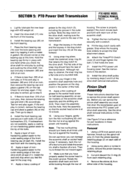
...Be careful to dislodge the shims (18). Put your hand down through the top of needle nose pliers. SECTION 5: PTO Power Unit Transmission PTO HORSE MODEL TECHNICAL MANUAL Page 5-3 4/90 PTO Power Unit Drive Shaft These instructions describe how to remove the oil seal (15) from the front bearing ...cap. 11. See the tiller parts catalog for removal instructions. Use snap ring pliers to remove the (external) snap ring (4) that is welded to its own part number and ...
...Be careful to dislodge the shims (18). Put your hand down through the top of needle nose pliers. SECTION 5: PTO Power Unit Transmission PTO HORSE MODEL TECHNICAL MANUAL Page 5-3 4/90 PTO Power Unit Drive Shaft These instructions describe how to remove the oil seal (15) from the front bearing ...cap. 11. See the tiller parts catalog for removal instructions. Use snap ring pliers to remove the (external) snap ring (4) that is welded to its own part number and ...
Technical Manual
Page 21
...retaining plug. 4. Tighten the hex nut/bushing securely with each turn the hex nut/bushing (6) until the nut is correct, go to accept the tiller attachment sleeve. 20. Insert the drive shaft (17) into the hole. Apply a layer of nonhardening gasket sealer to the tip of the eccentric ... not use force; Hold the bearing cap firmly in pullers, remove the pinion bearing retaining plugs. 3. SECTION 5: PTO Power Unit Transmission PTO HORSE MODEL TECHNICAL MANUAL Page 5-5 4/90 c. Slide the dog clutch on the front bearing. 7. Make sure that holds the lever. 21.
...retaining plug. 4. Tighten the hex nut/bushing securely with each turn the hex nut/bushing (6) until the nut is correct, go to accept the tiller attachment sleeve. 20. Insert the drive shaft (17) into the hole. Apply a layer of nonhardening gasket sealer to the tip of the eccentric ... not use force; Hold the bearing cap firmly in pullers, remove the pinion bearing retaining plugs. 3. SECTION 5: PTO Power Unit Transmission PTO HORSE MODEL TECHNICAL MANUAL Page 5-5 4/90 c. Slide the dog clutch on the front bearing. 7. Make sure that holds the lever. 21.
Technical Manual
Page 28
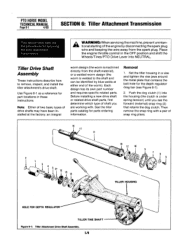
...a pair of snap ring pliers. 11 16 12 10 13 V " 14 Iv y TILLER HOUSING HOLE FOR DEPTH REGULATOR TILLER TINE SHAFT Figure 6-1: Tiller Attachment Drive Shaft Assembly. 103 Set the tiller housing in a vise and tighten the vise jaws around the metal plate that retains the ...has its own part number and requires specific related parts. Then remove the snap ring with . Removal 1. PTO HORSE MODEL TECHNICAL MANUAL Page 6-1 4/90 SECTION 6: Tiller Attachment Transmission This section describes the the procedures for parts ordering information. Place the engine throttle control in these ...
...a pair of snap ring pliers. 11 16 12 10 13 V " 14 Iv y TILLER HOUSING HOLE FOR DEPTH REGULATOR TILLER TINE SHAFT Figure 6-1: Tiller Attachment Drive Shaft Assembly. 103 Set the tiller housing in a vise and tighten the vise jaws around the metal plate that retains the ...has its own part number and requires specific related parts. Then remove the snap ring with . Removal 1. PTO HORSE MODEL TECHNICAL MANUAL Page 6-1 4/90 SECTION 6: Tiller Attachment Transmission This section describes the the procedures for parts ordering information. Place the engine throttle control in these ...
Technical Manual
Page 29
... the rear of the teeth in this edge is located. If the worm has a bluish color then proper lubrication has not been maintained; SECTION 6: Tiller Attachment Transmission PTO HORSE MODEL TECHNICAL MANUAL Page 6-2 4/90 3. Leave the drive shaft in the area where the oil seal seats, discard the drive shaft. • Inspect...
... the rear of the teeth in this edge is located. If the worm has a bluish color then proper lubrication has not been maintained; SECTION 6: Tiller Attachment Transmission PTO HORSE MODEL TECHNICAL MANUAL Page 6-2 4/90 3. Leave the drive shaft in the area where the oil seal seats, discard the drive shaft. • Inspect...


