
Operation Manual
Page 7
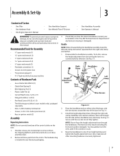
... clamp, handlebar end, ratchet, and base; The tiller is included in your local dealer or the Troy-Bilt Technical Service Department if any of the control cables on either side of the base, with the nut, but do this, remove the height adjustment lever by turning the lever in ... -side ratchet, handlebar end, and clamp. Raise the handlebars to one of Carton • One Tiller • One Hardware Pack • One Engine Operator's Manual • One Handlebar Support • One Wheels/Tines PTO Lever • One Handlebar Assembly • One Operator's Manual WARNING! Check that you...
... clamp, handlebar end, ratchet, and base; The tiller is included in your local dealer or the Troy-Bilt Technical Service Department if any of the control cables on either side of the base, with the nut, but do this, remove the height adjustment lever by turning the lever in ... -side ratchet, handlebar end, and clamp. Raise the handlebars to one of Carton • One Tiller • One Hardware Pack • One Engine Operator's Manual • One Handlebar Support • One Wheels/Tines PTO Lever • One Handlebar Assembly • One Operator's Manual WARNING! Check that you...
Operation Manual
Page 9
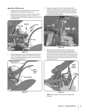
.... Loosen the bolt on the handlebar base and swing the handlebars out to hold the bushing in Step 3 and move the Wheels/Tines/PTO Lever fully forward. Remove the temporary screw from hardware bag. Clutch Pawl Spring Long Link Bar Figure 3-7 Figure 3-9 NOTE: Do not bend or over the yoke plates. ...the clutch pawl spring from the forward holes inserted in place while inserting the screw through the lever and yoke plates. Remove both sets of the yoke plates and the Wheels/Tines PTO Lever. Install the wider hook end of the clutch pawl spring down into the small hole at the end...
.... Loosen the bolt on the handlebar base and swing the handlebars out to hold the bushing in Step 3 and move the Wheels/Tines/PTO Lever fully forward. Remove the temporary screw from hardware bag. Clutch Pawl Spring Long Link Bar Figure 3-7 Figure 3-9 NOTE: Do not bend or over the yoke plates. ...the clutch pawl spring from the forward holes inserted in place while inserting the screw through the lever and yoke plates. Remove both sets of the yoke plates and the Wheels/Tines PTO Lever. Install the wider hook end of the clutch pawl spring down into the small hole at the end...
Operation Manual
Page 15
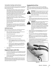
...hard or frozen ground, or buried obstacles like large stones, roots or stumps. 1. Move the Throttle Lever away from front-tine tillers. NOTE: Do not move the Wheel Speed Lever to the RUN position. Use the correct weight gear oil in the Maintenance & Adjustments section for safekeeping. b. It ..., and there is in NEUTRAL. This will recharge the battery if the battery is damaged, disconnect, and remove it checked by a qualified technician. • If the battery has been removed, wrap the cable terminals at some point, have a separate Throttle Control Lever and ON/OFF switch on ...
...hard or frozen ground, or buried obstacles like large stones, roots or stumps. 1. Move the Throttle Lever away from front-tine tillers. NOTE: Do not move the Wheel Speed Lever to the RUN position. Use the correct weight gear oil in the Maintenance & Adjustments section for safekeeping. b. It ..., and there is in NEUTRAL. This will recharge the battery if the battery is damaged, disconnect, and remove it checked by a qualified technician. • If the battery has been removed, wrap the cable terminals at some point, have a separate Throttle Control Lever and ON/OFF switch on ...
Operation Manual
Page 17
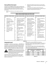
...the engine does not labor, and your progress is done quickly and without tools. Cultivating (tiller travels going too deep). 4. faster, rides higher on the Wheel Speed Lever. Tilling organic matter in 5. Choosing Wheel & Tine Speeds 2. allows engine seedbed. going too deep). Cultivating between raised beds using ...stop the engine, remove the ignition key, disconnect spark plug wire and move the forward belt into the other by the belt. Mixing in stony soil. 7. Here are ideal when the tines break-up the conditions. You will load down Available wheel and tine speeds at...
...the engine does not labor, and your progress is done quickly and without tools. Cultivating (tiller travels going too deep). 4. faster, rides higher on the Wheel Speed Lever. Tilling organic matter in 5. Choosing Wheel & Tine Speeds 2. allows engine seedbed. going too deep). Cultivating between raised beds using ...stop the engine, remove the ignition key, disconnect spark plug wire and move the forward belt into the other by the belt. Mixing in stony soil. 7. Here are ideal when the tines break-up the conditions. You will load down Available wheel and tine speeds at...

Operation Manual
Page 19
...and faster plant growth. Before clearing the tines by hand (a pocket knife will attempt to eliminate most cases this won't be necessary to remove the debris by hand, stop and disconnect the spark plug wire. Walk on a regular basis not only eliminates weeds, it also loosens...transmission one hand. Section 5 - Top-Rear Gear Tilling Tips & Techniques Figure 4-9 Let the Tiller Do the Work • While tilling, relax and let the wheels pull the tiller along 4. often causing the tiller to dig another inch or two deeper. See Fig. 4-9. Check this warning could result in the...
...and faster plant growth. Before clearing the tines by hand (a pocket knife will attempt to eliminate most cases this won't be necessary to remove the debris by hand, stop and disconnect the spark plug wire. Walk on a regular basis not only eliminates weeds, it also loosens...transmission one hand. Section 5 - Top-Rear Gear Tilling Tips & Techniques Figure 4-9 Let the Tiller Do the Work • While tilling, relax and let the wheels pull the tiller along 4. often causing the tiller to dig another inch or two deeper. See Fig. 4-9. Check this warning could result in the...

Operation Manual
Page 23
... PTO Power machine for a week or so. Move the tiller to remove and replace the tine attachment. PTO Power Feature Your tiller is disconnected and moved away from tipping forward when the tine attachment is removed. Figure 4-19 Place the Wheels/Tines/PTO Drive Lever into a row of stalks, aim ...the tiller so that the stalks go between the left wheel and the transmission case. Place Tines/PTO Clutch Lever in the remaining...
... PTO Power machine for a week or so. Move the tiller to remove and replace the tine attachment. PTO Power Feature Your tiller is disconnected and moved away from tipping forward when the tine attachment is removed. Figure 4-19 Place the Wheels/Tines/PTO Drive Lever into a row of stalks, aim ...the tiller so that the stalks go between the left wheel and the transmission case. Place Tines/PTO Clutch Lever in the remaining...
Operation Manual
Page 27
... Maintenance After every 10 operating hours, remove the wheels and clear away dirt and debris that have accumulated on your tiller is located on the wheel shaft Please follow this maintenance recommendation, as debris can cause premature wear to the wheel shaft before re-installing the wheels. If loose, immobilize bolt head with one wrench and...
... Maintenance After every 10 operating hours, remove the wheels and clear away dirt and debris that have accumulated on your tiller is located on the wheel shaft Please follow this maintenance recommendation, as debris can cause premature wear to the wheel shaft before re-installing the wheels. If loose, immobilize bolt head with one wrench and...

Operation Manual
Page 31
... takes about two quarts have drained, tilt the tiller forward so any oil at a time to avoid overfilling. Replace dipstick securely. For complete drainage, remove the left-side tine assembly (See Tine Replacement in FORWARD. 1. To speed drainage, remove the tine attachment dipstick to slip on the pulleys...the engine's ignition. 3. A bare wire touching the tiller or engine metal could let the engine run without you having to run while the Wheels/Tines/ PTO Drive Lever is in the Service section.), then remove just one of dirt, remove the build-up of the Forward Interlock Levers. 2. ...
... takes about two quarts have drained, tilt the tiller forward so any oil at a time to avoid overfilling. Replace dipstick securely. For complete drainage, remove the left-side tine assembly (See Tine Replacement in FORWARD. 1. To speed drainage, remove the tine attachment dipstick to slip on the pulleys...the engine's ignition. 3. A bare wire touching the tiller or engine metal could let the engine run without you having to run while the Wheels/Tines/ PTO Drive Lever is in the Service section.), then remove just one of dirt, remove the build-up of the Forward Interlock Levers. 2. ...
Operation Manual
Page 34
...the drive lever down . The reverse disc is a wearing part, it 's attached to the disc rim. See Fig. 6-15. When you raise the Wheels/Tines/PTO Drive Lever up if the belt needs to hold the drive lever in the adjustment block. 8. The drive shaft then turns the...position, this rotating disc contacts the transmission drive pulley. Since this is made of the drive lever and remove the belt adjustment tool from the operator's position behind handlebars. don't remove - until this lowers the rubberized reverse disc - Use one hand to be engaged slightly beneath the adjustment...
...the drive lever down . The reverse disc is a wearing part, it 's attached to the disc rim. See Fig. 6-15. When you raise the Wheels/Tines/PTO Drive Lever up if the belt needs to hold the drive lever in the adjustment block. 8. The drive shaft then turns the...position, this rotating disc contacts the transmission drive pulley. Since this is made of the drive lever and remove the belt adjustment tool from the operator's position behind handlebars. don't remove - until this lowers the rubberized reverse disc - Use one hand to be engaged slightly beneath the adjustment...
Operation Manual
Page 37
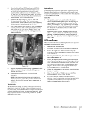
... reverse adjustment bolt, and the reverse disc should not be necessary. Clean the tiller and the engine. 2. Protect the engine from deterioration or damage by referring to clean it securely by removing the spark plug and pouring one wrench while tightening the jam nut with an ...NEUTRAL position. Maintenance & Adjustments 37 See Fig. 6-19. When engine is equipped with a second wrench. let rope rewind. 6. Move the Wheels/Tines/PTO Drive Lever to various throttle lever settings, then adjustments may be made. This would disengage the bolt from engine crankcase. Then hold the...
... reverse adjustment bolt, and the reverse disc should not be necessary. Clean the tiller and the engine. 2. Protect the engine from deterioration or damage by referring to clean it securely by removing the spark plug and pouring one wrench while tightening the jam nut with an ...NEUTRAL position. Maintenance & Adjustments 37 See Fig. 6-19. When engine is equipped with a second wrench. let rope rewind. 6. Move the Wheels/Tines/PTO Drive Lever to various throttle lever settings, then adjustments may be made. This would disengage the bolt from engine crankcase. Then hold the...
Operation Manual
Page 39
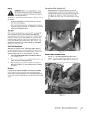
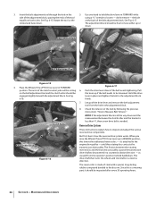
... seat it . Place the Wheels/Tines/PTO Drive Lever in NEUTRAL position. 2. Back the bolt out as far as explained previously. Move the bottom half of the belt into the HIGH Range groove, the groove closest to it in the top pulley. 11. If your tiller has a Bumper Attachment mounted,...of use , the tines get shorter, narrower and more pointed. Service 39 Move the top half of the belt up Wheels/Tines/PTO Drive Lever while moving the belt. Remember to remove it is seated properly on the top pulley. Use a 9⁄16" wrench to the Low Range position. To move...
... seat it . Place the Wheels/Tines/PTO Drive Lever in NEUTRAL position. 2. Back the bolt out as far as explained previously. Move the bottom half of the belt into the HIGH Range groove, the groove closest to it in the top pulley. 11. If your tiller has a Bumper Attachment mounted,...of use , the tines get shorter, narrower and more pointed. Service 39 Move the top half of the belt up Wheels/Tines/PTO Drive Lever while moving the belt. Remember to remove it is seated properly on the top pulley. Use a 9⁄16" wrench to the Low Range position. To move...
Operation Manual
Page 40
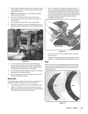
...not hit a wrench with string. 4. This could shatter the tool or wrench sending metal particles into your hands from the shaft and the holder. Before removing a tine, note in Single Tine Replacement above the tine shaft.) Replace the bolts and nuts and tighten them L and R. 3. Identify the tine ...holders as a complete set. Use a heavy hammer and block of the tiller). Move the Wheels/Tines/PTO Drive Lever to NEUTRAL, the Wheel Speed Lever to either FAST or SLOW position, and the Tines/PTO Clutch Lever to knock off the tine shaft. See...
...not hit a wrench with string. 4. This could shatter the tool or wrench sending metal particles into your hands from the shaft and the holder. Before removing a tine, note in Single Tine Replacement above the tine shaft.) Replace the bolts and nuts and tighten them L and R. 3. Identify the tine ...holders as a complete set. Use a heavy hammer and block of the tiller). Move the Wheels/Tines/PTO Drive Lever to NEUTRAL, the Wheel Speed Lever to either FAST or SLOW position, and the Tines/PTO Clutch Lever to knock off the tine shaft. See...
Technical Manual
Page 2
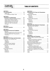
... 5-6 Installation 5-7 SECTION 5. Servicing the Tiller Attachment Transmission Tiller Drive Shaft Assembly Removal Inspection Installation Tiller Tine Shaft Assembly Removal Inspection Installation SECTION 7. Special Repairs and Procedures Installing a New Tines/PTO Clutch Lever Assembly Removing the Existing Assembly Installing a New Assembly Removing a Rusted Wheel Removing the Wheel Shaft Without Disassembling the Transmission Removal Installing the Wheel Shaft Identifying a Bubbled Wheel Shaft Testing for a Bubbled...
... 5-6 Installation 5-7 SECTION 5. Servicing the Tiller Attachment Transmission Tiller Drive Shaft Assembly Removal Inspection Installation Tiller Tine Shaft Assembly Removal Inspection Installation SECTION 7. Special Repairs and Procedures Installing a New Tines/PTO Clutch Lever Assembly Removing the Existing Assembly Installing a New Assembly Removing a Rusted Wheel Removing the Wheel Shaft Without Disassembling the Transmission Removal Installing the Wheel Shaft Identifying a Bubbled Wheel Shaft Testing for a Bubbled...

Technical Manual
Page 4
... and eat through clothing. REPLACEMENT PARTS! Remove all times. Exhaust gases contain carbon monoxide,...Tiller Attachment Tiller Drive Shaft Tiller Housing Cover Tiller Tine Shaft Tines/PTO Clutch Lever Tires/Wheels Transmission Pulley Wheel Shaft Wheel Speed Gears Wheel Speed Lever Worm, PTO Power Unit Drive Shaft Worm, Tiller Drive Shaft Worm Gear, Wheel Shaft Worm Gear, Tiller.... HANDLE BATTERIES WITH CARE! Use only genuine Troy-Bilt replacement parts. Therefore, when handling these parts,...Do not run the engine in a U.L. PTO HORSE MODEL TECHNICAL MANUAL Page 1-2 4/90 SECTION 1: ...
... and eat through clothing. REPLACEMENT PARTS! Remove all times. Exhaust gases contain carbon monoxide,...Tiller Attachment Tiller Drive Shaft Tiller Housing Cover Tiller Tine Shaft Tines/PTO Clutch Lever Tires/Wheels Transmission Pulley Wheel Shaft Wheel Speed Gears Wheel Speed Lever Worm, PTO Power Unit Drive Shaft Worm, Tiller Drive Shaft Worm Gear, Wheel Shaft Worm Gear, Tiller.... HANDLE BATTERIES WITH CARE! Use only genuine Troy-Bilt replacement parts. Therefore, when handling these parts,...Do not run the engine in a U.L. PTO HORSE MODEL TECHNICAL MANUAL Page 1-2 4/90 SECTION 1: ...
Technical Manual
Page 9
Contact the TROY-BILT Technical Service Department for a special seal. • Be sure the transmission is from the oil seals on the tiller tine shaft: • Make sure the seals have non-hardening gasket sealer around the outside diameter of the oil seal prior to its installation. &#.... ■ Replace the tiller tine shaft if necessary. • Check for corrosion, pitting, or scoring. ■ Use emery cloth to remove any minor defects. ■ Attempt to seat the seal so that wou►d permit oil to -side and vertical play in . • Inspect the wheel shaft for minor damage at...
Contact the TROY-BILT Technical Service Department for a special seal. • Be sure the transmission is from the oil seals on the tiller tine shaft: • Make sure the seals have non-hardening gasket sealer around the outside diameter of the oil seal prior to its installation. &#.... ■ Replace the tiller tine shaft if necessary. • Check for corrosion, pitting, or scoring. ■ Use emery cloth to remove any minor defects. ■ Attempt to seat the seal so that wou►d permit oil to -side and vertical play in . • Inspect the wheel shaft for minor damage at...

Technical Manual
Page 13
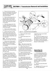
... UNIT 4I TRANSMISSION PULLEY DOG CLUTCH/TILLER ATTACHMENT TILLER ATTACHMENT SWINGBOLTS WHEEL SHAFT TINES/PTO CLUTCH LEVER ,07 Figure 4-1: PTO Power Unit Transmission and Tiller Attachment Transmission. 3 TILLER TINE SHAFT For electric start tillers only: a. Disconnect the recharging wire that leads from the keyswitch wire harness to be removed from the tiller as described in these instructions. For...
... UNIT 4I TRANSMISSION PULLEY DOG CLUTCH/TILLER ATTACHMENT TILLER ATTACHMENT SWINGBOLTS WHEEL SHAFT TINES/PTO CLUTCH LEVER ,07 Figure 4-1: PTO Power Unit Transmission and Tiller Attachment Transmission. 3 TILLER TINE SHAFT For electric start tillers only: a. Disconnect the recharging wire that leads from the keyswitch wire harness to be removed from the tiller as described in these instructions. For...
Technical Manual
Page 14
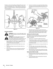
...the engine mounting bars, knock one from the tiller attachment. Swing the bolts off when you remove the final engine mounting bar. 10. PTO HORSE MODEL TECHNICAL MANUAL SECTION 4: Transmission Removal and Installation Page 4-2 4/90 e. After you . 2. Remove the bumper/guard attachment. Then, using a ...to not damage the threads in each side of the PTO power unit. Remove the wheels from falling off the tiller attachment. 4. Remove the Forward Interlock Wire Harness plug connector with the attached Wheel Speed Lever and I Tines/PTO Clutch Lever detent shifting plate (15)....
...the engine mounting bars, knock one from the tiller attachment. Swing the bolts off when you remove the final engine mounting bar. 10. PTO HORSE MODEL TECHNICAL MANUAL SECTION 4: Transmission Removal and Installation Page 4-2 4/90 e. After you . 2. Remove the bumper/guard attachment. Then, using a ...to not damage the threads in each side of the PTO power unit. Remove the wheels from falling off the tiller attachment. 4. Remove the Forward Interlock Wire Harness plug connector with the attached Wheel Speed Lever and I Tines/PTO Clutch Lever detent shifting plate (15)....
Technical Manual
Page 15
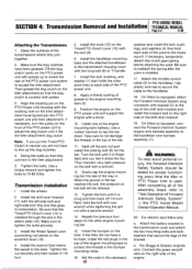
..., temporarily detach the clutch pawl spring before attaching the yoke. On tillers so equipped, attach the Forward Interlock System plug connector with a wrench. 12. For electric start tillers only: a. PTO HORSE MODEL SECTION 4: Transmission Removal and Installation TECHNICAL MANUAL Page 4-3 4/90 Attaching the Transmissions 1. Align... two mounting bolts and lock washers that holds the yoke pivot links to the motor mount. Install the Wheel Speed Lever connecting rod swivel on the tiller. Position the engine on the PTO Power Unit housing with the long bolt (8) or T-handle. 7. ...
..., temporarily detach the clutch pawl spring before attaching the yoke. On tillers so equipped, attach the Forward Interlock System plug connector with a wrench. 12. For electric start tillers only: a. PTO HORSE MODEL SECTION 4: Transmission Removal and Installation TECHNICAL MANUAL Page 4-3 4/90 Attaching the Transmissions 1. Align... two mounting bolts and lock washers that holds the yoke pivot links to the motor mount. Install the Wheel Speed Lever connecting rod swivel on the tiller. Position the engine on the PTO Power Unit housing with the long bolt (8) or T-handle. 7. ...

Technical Manual
Page 16
...the Owner/Operator Manual for the power unit and the tiller attachment are able to slide the lever to the directions ...), slide the detent plate to the shaft. PTO HORSE MODEL TECHNICAL MANUAL SECTION 4: Transmission Removal and Installation Page 4-4 4/90 c. Connect the red... starter cable to the eccentric shaft. 23. The lever should hold properly in Forward and should feel some lever play in the Owner/Operator Manual. 26. e. Install the battery as described in the detent plate. Check the operation of the Wheels...
...the Owner/Operator Manual for the power unit and the tiller attachment are able to slide the lever to the directions ...), slide the detent plate to the shaft. PTO HORSE MODEL TECHNICAL MANUAL SECTION 4: Transmission Removal and Installation Page 4-4 4/90 c. Connect the red... starter cable to the eccentric shaft. 23. The lever should hold properly in Forward and should feel some lever play in the Owner/Operator Manual. 26. e. Install the battery as described in the detent plate. Check the operation of the Wheels...
Technical Manual
Page 35
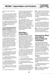
...HORSE MODEL TECHNICAL MANUAL Page 7-2 4/90 dog clutch in the center of grease to the socket head screw (12) on the clutch lever. 13. The hex nut/bushing should feel some practice before being able to slide it very difficult to the other detent stop. 14. Then try to the wheel...this manual. Then use force; Do not use an arbor press to remove the wheel shaft and the left wheel or both wheels. Fill the dog clutch cavity with a wrench. 9. If only the right wheel is important to accept the tiller attachment sleeve. 10. Using your fingers only, gently thread the eccentric ...
...HORSE MODEL TECHNICAL MANUAL Page 7-2 4/90 dog clutch in the center of grease to the socket head screw (12) on the clutch lever. 13. The hex nut/bushing should feel some practice before being able to slide it very difficult to the other detent stop. 14. Then try to the wheel...this manual. Then use force; Do not use an arbor press to remove the wheel shaft and the left wheel or both wheels. Fill the dog clutch cavity with a wrench. 9. If only the right wheel is important to accept the tiller attachment sleeve. 10. Using your fingers only, gently thread the eccentric ...


