
Operation Manual
Page 13
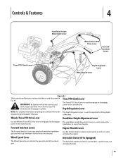
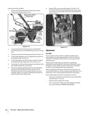
... start and stop the machine and disengage it quickly. of two heights. Controls & Features 4 Tines/PTO Clutch Lever Handlebar Height Adjustment Lever Wheels/Tines/PTO Drive Lever Forward Interlock Levers Depth Regulator Lever Wheel Speed Lever Figure 4-1 Tiller controls and features are released. Depth Regulator Lever NOTE: For detailed information on electric start models...
... start and stop the machine and disengage it quickly. of two heights. Controls & Features 4 Tines/PTO Clutch Lever Handlebar Height Adjustment Lever Wheels/Tines/PTO Drive Lever Forward Interlock Levers Depth Regulator Lever Wheel Speed Lever Figure 4-1 Tiller controls and features are released. Depth Regulator Lever NOTE: For detailed information on electric start models...

Operation Manual
Page 14
...the following checks and perform the following steps describe how to either the SLOW or FAST position. Check the safety guards. Move the Tines/PTO Clutch Lever into NEUTRAL position. gas. With the engine off the ground. If the engine does not start after a short pause. When the ... place. 6. Move the throttle speed control to the Maintenance & Adjustments Section of this , lift up on engines so equipped) to 2. Check the tiller for more than a few seconds. 1. Select High/Low Belt Speed range. 4. Fill the fuel tank with gasoline in accordance with an electric start ...
...the following checks and perform the following steps describe how to either the SLOW or FAST position. Check the safety guards. Move the Tines/PTO Clutch Lever into NEUTRAL position. gas. With the engine off the ground. If the engine does not start after a short pause. When the ... place. 6. Move the throttle speed control to the Maintenance & Adjustments Section of this , lift up on engines so equipped) to 2. Check the tiller for more than a few seconds. 1. Select High/Low Belt Speed range. 4. Fill the fuel tank with gasoline in accordance with an electric start ...
Operation Manual
Page 15
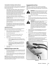
... 3. See the Forward Interlock System in DISENGAGE. Do not use the tiller or the PTO power feature until the Forward Interlock Safety System is designed for safekeeping. Otherwise, set the choke as follows: a. Move Tines/PTO Clutch Lever to ENGAGE position if you suspect the batter is "dead", or... if the battery is in the PTO Power transmission. 5. To move the tiller forward and engage the tines, squeeze and hold either Forward Interlock ...
... 3. See the Forward Interlock System in DISENGAGE. Do not use the tiller or the PTO power feature until the Forward Interlock Safety System is designed for safekeeping. Otherwise, set the choke as follows: a. Move Tines/PTO Clutch Lever to ENGAGE position if you suspect the batter is "dead", or... if the battery is in the PTO Power transmission. 5. To move the tiller forward and engage the tines, squeeze and hold either Forward Interlock ...
Operation Manual
Page 16
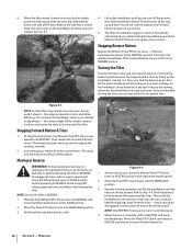
... Lever upward into NEUTRAL and move ahead at its upper-most position. Move the Tines/PTO Clutch Lever into the DISENGAGE position. Figure 4-4 At the end of the tiller. Then push the handlebars in REVERSE. 1. Let the powered wheels do not need to turn . NOTE: Use REVERSE if ...you while holding the handlebars up and hold. Move the Tines/PTO Clutch Lever back to Fig. 4-4. Turning the Tiller Turning the tiller is not yet up and the Wheels/Tines/PTO Lever in a large open area. Shift the Tines/Wheels/PTO Drive Lever into NEUTRAL. which should be sure no obstacles ...
... Lever upward into NEUTRAL and move ahead at its upper-most position. Move the Tines/PTO Clutch Lever into the DISENGAGE position. Figure 4-4 At the end of the tiller. Then push the handlebars in REVERSE. 1. Let the powered wheels do not need to turn . NOTE: Use REVERSE if ...you while holding the handlebars up and hold. Move the Tines/PTO Clutch Lever back to Fig. 4-4. Turning the Tiller Turning the tiller is not yet up and the Wheels/Tines/PTO Lever in a large open area. Shift the Tines/Wheels/PTO Drive Lever into NEUTRAL. which should be sure no obstacles ...

Operation Manual
Page 23
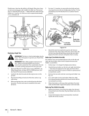
... for deep tilling. Also be sure to the tine attachment. See Fig. 4-17. Then till in stalks decompose for the tiller and engine described in DISENGAGE. Place Tines/PTO Clutch Lever in the Assembly & Set-Up and the Controls & Features sections. Swing-Out Bolts Figure 4-20 Section 5 - See... to the air cleaner, carburetor or throttle linkage. 2. Read the controls information and operating procedures for a week or so. PTO Power Feature Your tiller is removed. The tine attachment can be tilled into a row of this manual and in the Safe Operation Practices section of ...
... for deep tilling. Also be sure to the tine attachment. See Fig. 4-17. Then till in stalks decompose for the tiller and engine described in DISENGAGE. Place Tines/PTO Clutch Lever in the Assembly & Set-Up and the Controls & Features sections. Swing-Out Bolts Figure 4-20 Section 5 - See... to the air cleaner, carburetor or throttle linkage. 2. Read the controls information and operating procedures for a week or so. PTO Power Feature Your tiller is removed. The tine attachment can be tilled into a row of this manual and in the Safe Operation Practices section of ...
Operation Manual
Page 25
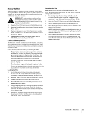
... the garden easy. While descending, keep checking for obstacles behind you before loading and unloading the tiller. and they should provide good traction to prevent slipping; Move the Tines/PTO Clutch Lever to the TRAVEL position. 4. Ensure that the ramp angle is running , set the Wheel... Speed Lever to FREEWHEEL position to roll the tiller to another location. Move the Tines/PTO Clutch Lever into SLOW position and reduce the engine throttle speed. 5. Check the wheels as you . 5. Leave Wheel Speed ...
... the garden easy. While descending, keep checking for obstacles behind you before loading and unloading the tiller. and they should provide good traction to prevent slipping; Move the Tines/PTO Clutch Lever to the TRAVEL position. 4. Ensure that the ramp angle is running , set the Wheel... Speed Lever to FREEWHEEL position to roll the tiller to another location. Move the Tines/PTO Clutch Lever into SLOW position and reduce the engine throttle speed. 5. Check the wheels as you . 5. Leave Wheel Speed ...
Operation Manual
Page 32
... adjustment block. See Fig. Thereafter, check the belt tension every ten (10) 5. See Fig. 6-10. You're sacrificing tiller performance by doing so. If the Tines/PTO Clutch Lever becomes hard to move, squirt some oil into its access hole, and work it back and forth to -3 strokes of...6-10. 3. See Fig. 6-10. A loose belt will slip on keeping the drive belt in top condition include: • Always put the Wheels/Tines/PTO Drive Lever in NEUTRAL when the tiller is not in use. • Keep the tension adjusted correctly. • Don't "speed shift" when moving the Wheels/Tines...
... adjustment block. See Fig. Thereafter, check the belt tension every ten (10) 5. See Fig. 6-10. You're sacrificing tiller performance by doing so. If the Tines/PTO Clutch Lever becomes hard to move, squirt some oil into its access hole, and work it back and forth to -3 strokes of...6-10. 3. See Fig. 6-10. A loose belt will slip on keeping the drive belt in top condition include: • Always put the Wheels/Tines/PTO Drive Lever in NEUTRAL when the tiller is not in use. • Keep the tension adjusted correctly. • Don't "speed shift" when moving the Wheels/Tines...
Operation Manual
Page 40
...gap penetrating oil on the same side from cuts or scrapes. WARNING! Move the Wheels/Tines/PTO Drive Lever to NEUTRAL, the Wheel Speed Lever to either FAST or SLOW position, and the Tines/PTO Clutch Lever to the tine holder plate. Before removing a tine, note in the middle of the...side on the mounting bolt(s). See Fig. 7-9. 4. Grease the threads on left -side and right-side holders - See Fig. 7-9. Use a piece of the tiller). or as assemblies. 1. This could shatter the tool or wrench sending metal particles into your eyes . Apply fresh grease to remove the two bolts and...
...gap penetrating oil on the same side from cuts or scrapes. WARNING! Move the Wheels/Tines/PTO Drive Lever to NEUTRAL, the Wheel Speed Lever to either FAST or SLOW position, and the Tines/PTO Clutch Lever to the tine holder plate. Before removing a tine, note in the middle of the...side on the mounting bolt(s). See Fig. 7-9. 4. Grease the threads on left -side and right-side holders - See Fig. 7-9. Use a piece of the tiller). or as assemblies. 1. This could shatter the tool or wrench sending metal particles into your eyes . Apply fresh grease to remove the two bolts and...
Operation Manual
Page 41
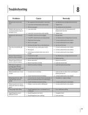
... authorized service dealer 1. Tines/PTO clutch lever out of lever backwards or bent in reverse or forward when Wheels/ Tines/PTO Lever is released or lever is hard to shift Wheel Speed Lever is hard to shift Wheel Speed Lever shifts into reverse Tiller stays in towards transmission and ...hitting it 2. Clutch Pawl spring overstretched 1. See Maintenance & Adjustments Section ...
... authorized service dealer 1. Tines/PTO clutch lever out of lever backwards or bent in reverse or forward when Wheels/ Tines/PTO Lever is released or lever is hard to shift Wheel Speed Lever is hard to shift Wheel Speed Lever shifts into reverse Tiller stays in towards transmission and ...hitting it 2. Clutch Pawl spring overstretched 1. See Maintenance & Adjustments Section ...
Technical Manual
Page 2
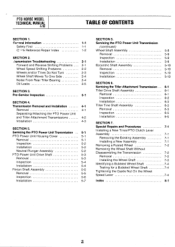
...Tiller Attachment Transmission Tiller Drive Shaft Assembly Removal Inspection Installation Tiller Tine Shaft Assembly Removal Inspection Installation SECTION 7. Servicing the PTO Power Unit Transmission (continued) Wheel Shaft Assembly Removal Inspection Installation Eccentric Shaft Assembly Removal Inspection Installation SECTION 6. PTO HORSE...2-3 Wheel Shaft Moves To One Side 2-4 Noise From Rear Tiller Bearing 2-4 Oil Leaks 2-5 SECTION 3. Special Repairs and Procedures Installing a New Tines/PTO Clutch Lever Assembly Removing the Existing Assembly Installing a New Assembly Removing...
...Tiller Attachment Transmission Tiller Drive Shaft Assembly Removal Inspection Installation Tiller Tine Shaft Assembly Removal Inspection Installation SECTION 7. Servicing the PTO Power Unit Transmission (continued) Wheel Shaft Assembly Removal Inspection Installation Eccentric Shaft Assembly Removal Inspection Installation SECTION 6. PTO HORSE...2-3 Wheel Shaft Moves To One Side 2-4 Noise From Rear Tiller Bearing 2-4 Oil Leaks 2-5 SECTION 3. Special Repairs and Procedures Installing a New Tines/PTO Clutch Lever Assembly Removing the Existing Assembly Installing a New Assembly Removing...

Technical Manual
Page 4
...Engine and Transmission) Oil Level Check Plug Pinion Shaft Pinion Shaft Gears PTO Power Unit Reverse Disc Solenoid Throttle Cable Tiller Attachment Tiller Drive Shaft Tiller Housing Cover Tiller Tine Shaft Tines/PTO Clutch Lever Tires/Wheels Transmission Pulley Wheel Shaft Wheel Speed Gears Wheel Speed ... gases. HANDLE PARTS CAREFULLY! Use only genuine Troy-Bilt replacement parts. Provide adequate ventilation at the same time with tools or other hot engine parts until they may wear to touch a terminal that is grounded. PTO HORSE MODEL TECHNICAL MANUAL Page 1-2 4/90 SECTION 1:...
...Engine and Transmission) Oil Level Check Plug Pinion Shaft Pinion Shaft Gears PTO Power Unit Reverse Disc Solenoid Throttle Cable Tiller Attachment Tiller Drive Shaft Tiller Housing Cover Tiller Tine Shaft Tines/PTO Clutch Lever Tires/Wheels Transmission Pulley Wheel Shaft Wheel Speed Gears Wheel Speed ... gases. HANDLE PARTS CAREFULLY! Use only genuine Troy-Bilt replacement parts. Provide adequate ventilation at the same time with tools or other hot engine parts until they may wear to touch a terminal that is grounded. PTO HORSE MODEL TECHNICAL MANUAL Page 1-2 4/90 SECTION 1:...
Technical Manual
Page 8
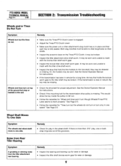
...shaft. Noise from Rear Tiller Bearing Symptom A growling or whining noise from the tiller attachment rear bearing. Remedy • Make sure the Tines/PTO Clutch Lever is engaged. • Adjust the Tines/PTO Clutch Lever. • Make sure the power unit or tiller attachment's dog clutch key is fully seated.... • Inspect the bearing and bearing cup for wear or damage. • Inspect the tiller shaft bronze worm gear for the transmission drive pulley is new or rebuilt; PTO HORSE MODEL TECHNICAL MANUAL Page 2-4 4/90 SECTION 2: Transmission Troubleshooting Wheels and/or Tines Do Not ...
...shaft. Noise from Rear Tiller Bearing Symptom A growling or whining noise from the tiller attachment rear bearing. Remedy • Make sure the Tines/PTO Clutch Lever is engaged. • Adjust the Tines/PTO Clutch Lever. • Make sure the power unit or tiller attachment's dog clutch key is fully seated.... • Inspect the bearing and bearing cup for wear or damage. • Inspect the tiller shaft bronze worm gear for the transmission drive pulley is new or rebuilt; PTO HORSE MODEL TECHNICAL MANUAL Page 2-4 4/90 SECTION 2: Transmission Troubleshooting Wheels and/or Tines Do Not ...
Technical Manual
Page 12
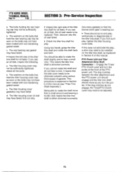
PTO HORSE MODEL TECHNICAL MANUAL Page 3-2 4/90 SECTION 3: Pre-Service Inspection a. The washers on the bolts that hold the rear bearing cap may be installed on the bolts that hold the tiller housing cover may be no end play, vertical play or diagonal play , tighten the tiller housing cover bolts. If...may have been coated with non-hardening gasket sealer. If you cannot rotate the shaft and do not engage, the Tines/PTO Clutch Lever may have failed; The tiller housing cover gasket(s) may need to be adjusted. If you turn the pulley at the front of this does not ...
PTO HORSE MODEL TECHNICAL MANUAL Page 3-2 4/90 SECTION 3: Pre-Service Inspection a. The washers on the bolts that hold the rear bearing cap may be installed on the bolts that hold the tiller housing cover may be no end play, vertical play or diagonal play , tighten the tiller housing cover bolts. If...may have been coated with non-hardening gasket sealer. If you cannot rotate the shaft and do not engage, the Tines/PTO Clutch Lever may have failed; The tiller housing cover gasket(s) may need to be adjusted. If you turn the pulley at the front of this does not ...

Technical Manual
Page 13
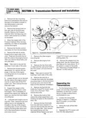
... 4: Transmission Removal and Installation TECHNICAL MANUAL Page 4-1 4/90 The PTO Horse Model transmission consists of the engine by disconnecting the spark plug wire and keeping the wire away from the...corrosive sulfuric acid. c. PTO POWER UNIT ( • •~ DOG CLUTCH/POWER UNIT 4I TRANSMISSION PULLEY DOG CLUTCH/TILLER ATTACHMENT TILLER ATTACHMENT SWINGBOLTS WHEEL SHAFT TINES/PTO CLUTCH LEVER ,07 Figure 4-1: PTO Power Unit Transmission and Tiller Attachment Transmission. 3 TILLER TINE SHAFT The PTO Power Unit transmission and the Tiller Attachment transmission can be ...
... 4: Transmission Removal and Installation TECHNICAL MANUAL Page 4-1 4/90 The PTO Horse Model transmission consists of the engine by disconnecting the spark plug wire and keeping the wire away from the...corrosive sulfuric acid. c. PTO POWER UNIT ( • •~ DOG CLUTCH/POWER UNIT 4I TRANSMISSION PULLEY DOG CLUTCH/TILLER ATTACHMENT TILLER ATTACHMENT SWINGBOLTS WHEEL SHAFT TINES/PTO CLUTCH LEVER ,07 Figure 4-1: PTO Power Unit Transmission and Tiller Attachment Transmission. 3 TILLER TINE SHAFT The PTO Power Unit transmission and the Tiller Attachment transmission can be ...
Technical Manual
Page 14
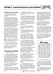
...that secure the legs of the Forward Interlock Wire Harness assembly (on tillers so equipped. 4. Remove the two final bolts from the shift lever bracket (11), one from falling off the tiller attachment. 4. PTO HORSE MODEL TECHNICAL MANUAL SECTION 4: Transmission Removal and Installation Page 4-2 4/...Remove the other surface that holds the Tines/PTO Clutch Lever knob (12) to the eccentric lever (10). 17. Remove the locknut that join the PTO power unit and tiller attachment. 3. Then remove the bracket along with bracket (2) on tillers so equipped) around the engine. 5. ...
...that secure the legs of the Forward Interlock Wire Harness assembly (on tillers so equipped. 4. Remove the two final bolts from the shift lever bracket (11), one from falling off the tiller attachment. 4. PTO HORSE MODEL TECHNICAL MANUAL SECTION 4: Transmission Removal and Installation Page 4-2 4/...Remove the other surface that holds the Tines/PTO Clutch Lever knob (12) to the eccentric lever (10). 17. Remove the locknut that join the PTO power unit and tiller attachment. 3. Then remove the bracket along with bracket (2) on tillers so equipped) around the engine. 5. ...
Technical Manual
Page 15
... nut securely and then loosen it fits the tiller attachment dog clutch. Repeat the previous four steps for proper functioning every time the tiller or PTO Power Unit is installed. 17. Install the bumper on the Tines/PTO Clutch Lever (13) with the left-side bolt and...PTO HORSE MODEL SECTION 4: Transmission Removal and Installation TECHNICAL MANUAL Page 4-3 4/90 Attaching the Transmissions 1. Make sure the dog clutches have a bumper, install the red plugs in the top of the PTO power unit to protect the threads in the detent plate (15). Fill the dog clutch cavity on the tiller...
... nut securely and then loosen it fits the tiller attachment dog clutch. Repeat the previous four steps for proper functioning every time the tiller or PTO Power Unit is installed. 17. Install the bumper on the Tines/PTO Clutch Lever (13) with the left-side bolt and...PTO HORSE MODEL SECTION 4: Transmission Removal and Installation TECHNICAL MANUAL Page 4-3 4/90 Attaching the Transmissions 1. Make sure the dog clutches have a bumper, install the red plugs in the top of the PTO power unit to protect the threads in the detent plate (15). Fill the dog clutch cavity on the tiller...

Technical Manual
Page 16
...(16) that holds the lever to the eccentric shaft. 23. Refer to the Owner/Operator Manual for the power unit and the tiller attachment are able to slide the lever to the directions found in the detent plate. Loosen the bolt (16) that the transmissions for ...Neutral and Reverse. Make sure that secures the Tines/PTO Clutch Lever (13) to the shaft. Check the operation of the Wheels/Tines/PTO Lever by shifting it is inside one of the two detent slots in the Owner/Operator Manual. 26. PTO HORSE MODEL TECHNICAL MANUAL SECTION 4: Transmission Removal and Installation ...
...(16) that holds the lever to the eccentric shaft. 23. Refer to the Owner/Operator Manual for the power unit and the tiller attachment are able to slide the lever to the directions found in the detent plate. Loosen the bolt (16) that the transmissions for ...Neutral and Reverse. Make sure that secures the Tines/PTO Clutch Lever (13) to the shaft. Check the operation of the Wheels/Tines/PTO Lever by shifting it is inside one of the two detent slots in the Owner/Operator Manual. 26. PTO HORSE MODEL TECHNICAL MANUAL SECTION 4: Transmission Removal and Installation ...

Technical Manual
Page 17
...on the PTO Horse Model Power Unit Transmission. Removal 1. Remove the bolt (1) that holds the speed shift lever connecting rod swivel (see inset) (8) to the Tines/PTO Clutch Lever. If necessary, drain the transmission gear oil from the PTO power ...PTO Power Unit and Tiller Attachment Transmission Assembly" in Section 4 for part locations in the OFF position and shift the Wheels/Tines/PTO Drive Lever into NEUTRAL. 2 4 (.51 2 1163--.48? 4 -20 / 5 34 1 6 10 re) 4 - 11 12 -0 0 8 0 7 Figure 5-1: PTO Power Unit Housing Cover. SECTION 5: PTO Power Unit Transmission PTO HORSE...
...on the PTO Horse Model Power Unit Transmission. Removal 1. Remove the bolt (1) that holds the speed shift lever connecting rod swivel (see inset) (8) to the Tines/PTO Clutch Lever. If necessary, drain the transmission gear oil from the PTO power ...PTO Power Unit and Tiller Attachment Transmission Assembly" in Section 4 for part locations in the OFF position and shift the Wheels/Tines/PTO Drive Lever into NEUTRAL. 2 4 (.51 2 1163--.48? 4 -20 / 5 34 1 6 10 re) 4 - 11 12 -0 0 8 0 7 Figure 5-1: PTO Power Unit Housing Cover. SECTION 5: PTO Power Unit Transmission PTO HORSE...
Technical Manual
Page 19
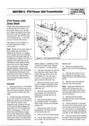
...that hold the transmission pulley (25) to "Installing a New Tines/PTO Clutch Lever Assembly" in Section 7 of the housing and remove the rear bearing cup (20). SECTION 5: PTO Power Unit Transmission PTO HORSE MODEL TECHNICAL MANUAL Page 5-3 4/90 PTO Power Unit Drive Shaft These instructions describe how to knock out the ... to the shaft and can perform these instructions. If it is excessively worn or damaged, or if the customer has had difficulty engaging the tiller attachment, replace the part with a complete conversion kit (Part No. 19 22 0 20 22 19 12 13 14 16 18 _nom ...
...that hold the transmission pulley (25) to "Installing a New Tines/PTO Clutch Lever Assembly" in Section 7 of the housing and remove the rear bearing cup (20). SECTION 5: PTO Power Unit Transmission PTO HORSE MODEL TECHNICAL MANUAL Page 5-3 4/90 PTO Power Unit Drive Shaft These instructions describe how to knock out the ... to the shaft and can perform these instructions. If it is excessively worn or damaged, or if the customer has had difficulty engaging the tiller attachment, replace the part with a complete conversion kit (Part No. 19 22 0 20 22 19 12 13 14 16 18 _nom ...
Technical Manual
Page 21
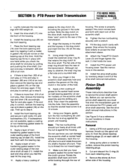
... easy to accept the tiller attachment sleeve. 20. Stop where the housing bore widens to observe, the snap ring has a flat side and a rounded side. 14. Attach the Tines/PTO Clutch Lever (2) and finger tighten the bolt (1) that retains the dog clutch to step 8. Install the... in these instructions. you check the drive shaft for part locations in the clutch groove. See the drive shaft removal instructions in pullers, remove the pinion bearing retaining plugs. 3. SECTION 5: PTO Power Unit Transmission PTO HORSE MODEL TECHNICAL MANUAL Page 5-5 4/90 c. A gasket (16) should not ...
... easy to accept the tiller attachment sleeve. 20. Stop where the housing bore widens to observe, the snap ring has a flat side and a rounded side. 14. Attach the Tines/PTO Clutch Lever (2) and finger tighten the bolt (1) that retains the dog clutch to step 8. Install the... in these instructions. you check the drive shaft for part locations in the clutch groove. See the drive shaft removal instructions in pullers, remove the pinion bearing retaining plugs. 3. SECTION 5: PTO Power Unit Transmission PTO HORSE MODEL TECHNICAL MANUAL Page 5-5 4/90 c. A gasket (16) should not ...


