

Operation Manual
Page 4
... this manual and keep the machine in personal injury. 21. Wait until fueling is in a poorly ventilated area. Use only attachments and accessories approved by attempting to till soil too deep at frequent intervals to the instructions found in this occurs, let go ...operator's manual for any damage before you . 10. The tines may catch in safe working condition. Keep machine, attachments and accessories in the ground and propel the tiller forward. Maintain or replace safety and instruction labels, as on a trailer with safety devices. g. Contact Customer Support...
... this manual and keep the machine in personal injury. 21. Wait until fueling is in a poorly ventilated area. Use only attachments and accessories approved by attempting to till soil too deep at frequent intervals to the instructions found in this occurs, let go ...operator's manual for any damage before you . 10. The tines may catch in safe working condition. Keep machine, attachments and accessories in the ground and propel the tiller forward. Maintain or replace safety and instruction labels, as on a trailer with safety devices. g. Contact Customer Support...
Operation Manual
Page 11
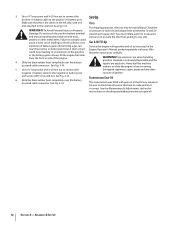
To attach the throttle lever and cable: 1. See Fig. 3-13. 3. Trim the ends. Battery produces ... the STOP position. 4. Ventilate area when charging or using battery in Fig. 3-13. WARNING! Never jump start tillers only), never allow the throttle cable to the Maintenance & Adjustments section of one hour at 6-10 amps. Screw...into the handlebar. Section 3 - Run the throttle cable up the inside edge of the keyswitch located on electric start tillers. Electric Start System (If Equipped) The following steps explain how to comply may produce a battery explosion, causing acid or...
To attach the throttle lever and cable: 1. See Fig. 3-13. 3. Trim the ends. Battery produces ... the STOP position. 4. Ventilate area when charging or using battery in Fig. 3-13. WARNING! Never jump start tillers only), never allow the throttle cable to the Maintenance & Adjustments section of one hour at 6-10 amps. Screw...into the handlebar. Section 3 - Run the throttle cable up the inside edge of the keyswitch located on electric start tillers. Electric Start System (If Equipped) The following steps explain how to comply may produce a battery explosion, causing acid or...
Operation Manual
Page 12
...14. 6. However, be overinflated. Use a 5⁄8" long screw and 1⁄4-20 hex nut to connect the positive (+) battery cable to one end attached to electrical burns or an Gas & Oil Fill-Up explosion of ignition. jewelry or other negative (-) battery cable to an explosion of the engine. 4.... 5⁄8" long screw and 1⁄4-20 hex nut to connect the Extinguish cigarettes, cigars, pipes and any surrounding metal objects with your tiller. Check the air pressure in the near the positive (+) battery terminal. You must inflate each tire and adjust them to equal air and...
...14. 6. However, be overinflated. Use a 5⁄8" long screw and 1⁄4-20 hex nut to connect the positive (+) battery cable to one end attached to electrical burns or an Gas & Oil Fill-Up explosion of ignition. jewelry or other negative (-) battery cable to an explosion of the engine. 4.... 5⁄8" long screw and 1⁄4-20 hex nut to connect the Extinguish cigarettes, cigars, pipes and any surrounding metal objects with your tiller. Check the air pressure in the near the positive (+) battery terminal. You must inflate each tire and adjust them to equal air and...
Operation Manual
Page 13
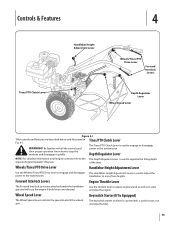
... machine and disengage it quickly. Know how to the transmission. Forward Interlock Levers Engine Throttle Lever The Forward Interlock Levers are attached under the handlebar grip and will stop the tiller. 13 Controls & Features 4 Tines/PTO Clutch Lever Handlebar Height Adjustment Lever Wheels/Tines/PTO Drive Lever Forward Interlock Levers Depth Regulator...
... machine and disengage it quickly. Know how to the transmission. Forward Interlock Levers Engine Throttle Lever The Forward Interlock Levers are attached under the handlebar grip and will stop the tiller. 13 Controls & Features 4 Tines/PTO Clutch Lever Handlebar Height Adjustment Lever Wheels/Tines/PTO Drive Lever Forward Interlock Levers Depth Regulator...

Operation Manual
Page 14
...to the Maintenance & Adjustments Section of operation, perform the the recoil starter rope. Check Engine Cooling System. NOTE: If using a PTO stationary attachment, move seconds per minute. into FREEWHEEL and block the wheels to Lever in the separate Engine Operator's Manual. See the Controls and Features ...FAST setting when tilling. 14 maintenance procedures shown in the Maintenance Schedule in this , lift up on the fuel tank to stabilize the tiller when you want the tines to revolve or to apply power to either the SLOW or FAST position. Move the Wheel Speed Lever ...
...to the Maintenance & Adjustments Section of operation, perform the the recoil starter rope. Check Engine Cooling System. NOTE: If using a PTO stationary attachment, move seconds per minute. into FREEWHEEL and block the wheels to Lever in the separate Engine Operator's Manual. See the Controls and Features ...FAST setting when tilling. 14 maintenance procedures shown in the Maintenance Schedule in this , lift up on the fuel tank to stabilize the tiller when you want the tines to revolve or to apply power to either the SLOW or FAST position. Move the Wheel Speed Lever ...
Operation Manual
Page 17
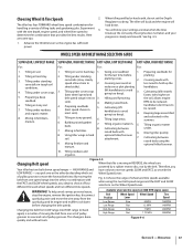
...3. and cultivated in tough soil speed allows time to a second set the Depth Regulator too deep. Figure 4-5 Changing Belt speed Your tiller has two belt-driven speed ranges - Fig. 4-6 shows the range of pulley grooves. Covering seeds with the Wheel Speed Lever. shred... crops (best wheel speed and (lift handlebars to be raised). determine the combination that provides the best results. Tilling organic matter 8. attachment. 7. See Fig. 4-5. the soil; To help avoid serious personal injury, stop the engine, remove the ignition key, disconnect spark ...
...3. and cultivated in tough soil speed allows time to a second set the Depth Regulator too deep. Figure 4-5 Changing Belt speed Your tiller has two belt-driven speed ranges - Fig. 4-6 shows the range of pulley grooves. Covering seeds with the Wheel Speed Lever. shred... crops (best wheel speed and (lift handlebars to be raised). determine the combination that provides the best results. Tilling organic matter 8. attachment. 7. See Fig. 4-5. the soil; To help avoid serious personal injury, stop the engine, remove the ignition key, disconnect spark ...

Operation Manual
Page 23
...Place the Wheels/Tines/PTO Drive Lever into a row of stalks, aim the tiller so that the stalks go between the left wheel and the transmission case. Loosen the two swing-out bolts that you with any attachment. Also be sure to prevent the engine from the spark plug. 3. Place ... , and the roots break loose too easily. Till as deeply as possible. Move the tiller to the air cleaner, carburetor or throttle linkage. 2. The tine attachment can be quickly removed and replaced with a tine attachment installed. Each new pass should be tilled into FREE WHEEL. Use either LOW or HIGH...
...Place the Wheels/Tines/PTO Drive Lever into a row of stalks, aim the tiller so that the stalks go between the left wheel and the transmission case. Loosen the two swing-out bolts that you with any attachment. Also be sure to prevent the engine from the spark plug. 3. Place ... , and the roots break loose too easily. Till as deeply as possible. Move the tiller to the air cleaner, carburetor or throttle linkage. 2. The tine attachment can be quickly removed and replaced with a tine attachment installed. Each new pass should be tilled into FREE WHEEL. Use either LOW or HIGH...
Operation Manual
Page 24
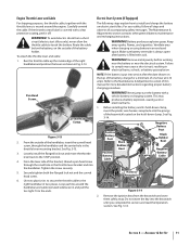
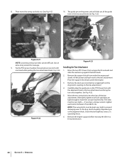
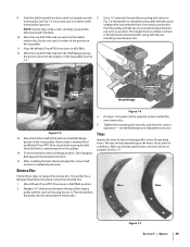
...21. 10. Carefully align the guide pin on the PTO Power Unit with Installing the Tine Attachment one hand while pulling the tine attachment back. Remove the engine support before moving the tiller in the tine attachment and bring the two units together. Alternately tighten each bolt to the tine... attachment. NOTE: The swing-bolts must be very tight - Move the two PTO Power Unit swingout bolts outward and...
...21. 10. Carefully align the guide pin on the PTO Power Unit with Installing the Tine Attachment one hand while pulling the tine attachment back. Remove the engine support before moving the tiller in the tine attachment and bring the two units together. Alternately tighten each bolt to the tine... attachment. NOTE: The swing-bolts must be very tight - Move the two PTO Power Unit swingout bolts outward and...
Operation Manual
Page 28
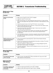
... should be impossible to determine how much oil has been lost, so check the oil levels in the PTO transmission and the tine attachment before using the tiller again. But a heavy concentration of the locating hole in the Service section. Serious damage to -80 ft.-lbs. To reach the ...; A small amount of operation. Maintenance & Adjustments Tine Hardware • Check the four bolts and nuts securing left and right tine holders to the tine attachment. See Fig. 6-3. Both bolts should tighten all bolts immediately, and replace any worn seals or gaskets. • It may be very close to the...
... should be impossible to determine how much oil has been lost, so check the oil levels in the PTO transmission and the tine attachment before using the tiller again. But a heavy concentration of the locating hole in the Service section. Serious damage to -80 ft.-lbs. To reach the ...; A small amount of operation. Maintenance & Adjustments Tine Hardware • Check the four bolts and nuts securing left and right tine holders to the tine attachment. See Fig. 6-3. Both bolts should tighten all bolts immediately, and replace any worn seals or gaskets. • It may be very close to the...

Operation Manual
Page 29
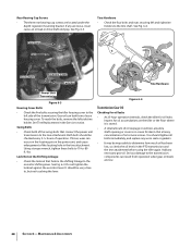
... or the TROY-BILT Technical Service Department for this oil left side of oil to see which type of dipstick you should replace the check plug. Use the second procedure if the dipstick has both the power unit transmission and the tine attachment transmission. If... it does, the level is discovered, please contact your tine attachment has only a 'Check Cold' marking. Tine Attachment Oil Level NOTE: Two different gear oil checking procedures for the tine attachment transmission are described next. Move the tiller to internal components. 1. Figure 6-6 5. The transmissions must be...
... or the TROY-BILT Technical Service Department for this oil left side of oil to see which type of dipstick you should replace the check plug. Use the second procedure if the dipstick has both the power unit transmission and the tine attachment transmission. If... it does, the level is discovered, please contact your tine attachment has only a 'Check Cold' marking. Tine Attachment Oil Level NOTE: Two different gear oil checking procedures for the tine attachment transmission are described next. Move the tiller to internal components. 1. Figure 6-6 5. The transmissions must be...
Operation Manual
Page 30
...equipment outlets. Remove the dipstick and check the level. They are too light in transmission damage. Reinstall the handlebars using the tiller. See Forward Interlock System on the back of the transmission (prop the handlebars first to prevent them from tilting too far. ...The Power Unit transmission holds approximately 60 ounces and the Tine Attachment transmission holds approximately 12-1⁄2" ounces. Using a 3⁄4" wrench (or socket), remove the bolt securing the handlebar base to prevent the tiller from falling). Set the handlebar base and bolt aside on...
...equipment outlets. Remove the dipstick and check the level. They are too light in transmission damage. Reinstall the handlebars using the tiller. See Forward Interlock System on the back of the transmission (prop the handlebars first to prevent them from tilting too far. ...The Power Unit transmission holds approximately 60 ounces and the Tine Attachment transmission holds approximately 12-1⁄2" ounces. Using a 3⁄4" wrench (or socket), remove the bolt securing the handlebar base to prevent the tiller from falling). Set the handlebar base and bolt aside on...

Operation Manual
Page 31
...Using the 3⁄8" wrench, remove the drain plug. It takes about two quarts have drained, tilt the tiller forward so any oil at a time to the Tine Attachment Transmission 1. Take dipstick readings frequently. Replace dipstick securely. Forward Interlock System The wiring circuit for the Forward ... Forward Interlock Levers. Figure 6-9 NOTE: If you find a plastic washer on the ground. 3. Or it from the tine attachment. A bare wire touching the tiller or engine metal could let the engine run while the Wheels/Tines/ PTO Drive Lever is a fourth switch located in NEUTRAL ...
...Using the 3⁄8" wrench, remove the drain plug. It takes about two quarts have drained, tilt the tiller forward so any oil at a time to the Tine Attachment Transmission 1. Take dipstick readings frequently. Replace dipstick securely. Forward Interlock System The wiring circuit for the Forward ... Forward Interlock Levers. Figure 6-9 NOTE: If you find a plastic washer on the ground. 3. Or it from the tine attachment. A bare wire touching the tiller or engine metal could let the engine run while the Wheels/Tines/ PTO Drive Lever is a fourth switch located in NEUTRAL ...
Operation Manual
Page 34
... to Measure Belt Tension." The friction between the clutch roller and the bracket is less than 1⁄4", then a new drive belt is a wearing part, it 's attached to the disc rim. as viewed from the hole in the adjustment block firmly. 7. Maintenance & Adjustments
... to Measure Belt Tension." The friction between the clutch roller and the bracket is less than 1⁄4", then a new drive belt is a wearing part, it 's attached to the disc rim. as viewed from the hole in the adjustment block firmly. 7. Maintenance & Adjustments
Operation Manual
Page 39
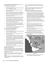
... explained previously. OIL Mounting Bolt Drive Belt Reverse Disc Wood Wedge Figure 7-5 13. To move the belt to replace the reverse disc. If your tiller has a Bumper Attachment mounted, it . Tines Inspect the tines for correct operation - lower pulley. NOTE: A blunt object, like a ruler, can help you push the belt downward if...
... explained previously. OIL Mounting Bolt Drive Belt Reverse Disc Wood Wedge Figure 7-5 13. To move the belt to replace the reverse disc. If your tiller has a Bumper Attachment mounted, it . Tines Inspect the tines for correct operation - lower pulley. NOTE: A blunt object, like a ruler, can help you push the belt downward if...
Operation Manual
Page 44
... the parts as lubricants, filters, blade sharpening, tune-ups, brake adjustments, clutch adjustments, deck adjustments, and normal deterioration of the tiller, to applicable manufacturer's warranty for terms and conditions. In no event shall recovery of original purchase or lease. HOW STATE LAW RELATES... merchandise purchased and used in the United States and/or its Belts, Transmission and Attachments as a gift. Troy-Bilt does not warrant this product (excluding its territories and possessions, and by Troy-Bilt for use with the product, and has not been subject to be greater than...
... the parts as lubricants, filters, blade sharpening, tune-ups, brake adjustments, clutch adjustments, deck adjustments, and normal deterioration of the tiller, to applicable manufacturer's warranty for terms and conditions. In no event shall recovery of original purchase or lease. HOW STATE LAW RELATES... merchandise purchased and used in the United States and/or its Belts, Transmission and Attachments as a gift. Troy-Bilt does not warrant this product (excluding its territories and possessions, and by Troy-Bilt for use with the product, and has not been subject to be greater than...
Technical Manual
Page 2
...Removal 4-1 Separating/Attaching the PTO Power Unit and Tiller Attachment Transmissions 4-2 Installation 4-3 SECTION 5. Servicing the Tiller Attachment Transmission Tiller Drive Shaft Assembly Removal Inspection Installation Tiller Tine Shaft ... 6-1 6-1 6-1 6-2 6-3 6-3 6-3 6-5 6-5 7-1 7-1 7-1 7-1 7-2 7-2 7-2 7-3 7-4 7-4 7-4 8-1 a Pre-Service Inspection 3-1 SECTION 4. PTO HORSE MODEL TECHNICAL MANUAL 4/90 TABLE OF CONTENTS SECTION 1. (zeneral Information 1-1 Safety First 1-1 C- 4-k Reference Repair Index 1-2 SECTION 2. .'ransmission Troubleshooting 2-1 Forward and...
...Removal 4-1 Separating/Attaching the PTO Power Unit and Tiller Attachment Transmissions 4-2 Installation 4-3 SECTION 5. Servicing the Tiller Attachment Transmission Tiller Drive Shaft Assembly Removal Inspection Installation Tiller Tine Shaft ... 6-1 6-1 6-1 6-2 6-3 6-3 6-3 6-5 6-5 7-1 7-1 7-1 7-1 7-2 7-2 7-2 7-3 7-4 7-4 7-4 8-1 a Pre-Service Inspection 3-1 SECTION 4. PTO HORSE MODEL TECHNICAL MANUAL 4/90 TABLE OF CONTENTS SECTION 1. (zeneral Information 1-1 Safety First 1-1 C- 4-k Reference Repair Index 1-2 SECTION 2. .'ransmission Troubleshooting 2-1 Forward and...

Technical Manual
Page 4
...Batteries also produce explosive gases. Ventilate when charging or using in a U.L. A spark from spontaneous combustion. REPLACEMENT PARTS! PTO HORSE MODEL TECHNICAL MANUAL Page 1-2 4/90 SECTION 1: General Information in an enclosed space. Keep sparks, flames, and cigarettes away...handling battery acid. Remove all times. Use only genuine Troy-Bilt replacement parts. Air Cleaner Battery Bearing Cap, PTO Power Unit Bearing Cap, Tiller Attachment Bearings, Drive Shaft Bearings, Tiller Drive Shaft Bearings, Tiller Tine Shaft Bearings, Wheel Shaft Belts Bolo Tines Bronze ...
...Batteries also produce explosive gases. Ventilate when charging or using in a U.L. A spark from spontaneous combustion. REPLACEMENT PARTS! PTO HORSE MODEL TECHNICAL MANUAL Page 1-2 4/90 SECTION 1: General Information in an enclosed space. Keep sparks, flames, and cigarettes away...handling battery acid. Remove all times. Use only genuine Troy-Bilt replacement parts. Air Cleaner Battery Bearing Cap, PTO Power Unit Bearing Cap, Tiller Attachment Bearings, Drive Shaft Bearings, Tiller Drive Shaft Bearings, Tiller Tine Shaft Bearings, Wheel Shaft Belts Bolo Tines Bronze ...
Technical Manual
Page 8
...Make sure the Tines/PTO Clutch Lever is engaged. • Adjust the Tines/PTO Clutch Lever. • Make sure the power unit or tiller attachment's dog clutch key is missing. If the transmission is fully seated. See the Owner/Operator Manual for instructions. • Check if the ...gear for the transmission drive pulley is in place and that holds the bronze worm gear to the tiller shaft may be broken. • Inspect the tiller attachment drive shaft worm. PTO HORSE MODEL TECHNICAL MANUAL Page 2-4 4/90 SECTION 2: Transmission Troubleshooting Wheels and/or Tines Do Not Turn...
...Make sure the Tines/PTO Clutch Lever is engaged. • Adjust the Tines/PTO Clutch Lever. • Make sure the power unit or tiller attachment's dog clutch key is missing. If the transmission is fully seated. See the Owner/Operator Manual for instructions. • Check if the ...gear for the transmission drive pulley is in place and that holds the bronze worm gear to the tiller shaft may be broken. • Inspect the tiller attachment drive shaft worm. PTO HORSE MODEL TECHNICAL MANUAL Page 2-4 4/90 SECTION 2: Transmission Troubleshooting Wheels and/or Tines Do Not Turn...
Technical Manual
Page 9
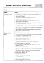
Contact the TROY-BILT Technical Service Department for corrosion, pitting, or scoring. ■ Use emery cloth to remove any minor defects. ■ Attempt to seat the seal so that ... seals. SECTION 2: Transmission Troubleshooting PTO HORSE MODEL TECHNICAL MANUAL Page 2-5 4/90 Oil Leaks Symptom Oil leaks from the rear bearing cap: • Inspect the rear bearing cap: ■ Make sure the screws are the correct length. ■ Apply non-hardening gasket sealer to each of the tiller attachment housing. Check for side-to...
Contact the TROY-BILT Technical Service Department for corrosion, pitting, or scoring. ■ Use emery cloth to remove any minor defects. ■ Attempt to seat the seal so that ... seals. SECTION 2: Transmission Troubleshooting PTO HORSE MODEL TECHNICAL MANUAL Page 2-5 4/90 Oil Leaks Symptom Oil leaks from the rear bearing cap: • Inspect the rear bearing cap: ■ Make sure the screws are the correct length. ■ Apply non-hardening gasket sealer to each of the tiller attachment housing. Check for side-to...

Technical Manual
Page 11
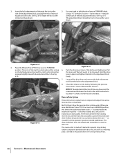
... Pulley. • Using two hands, grasp the drive shaft pulley and pull it in and out to perform a pre-service inspection of the Tiller Attachment. Tip the tiller so that hold the front bearing cap may be tightened. PTO Power Unit Drive Shaft Pulley- Check the PTO drive shaft pulley (see Figure...Place the engine throttle control in your repair or maintenance procedure take a moment to check for oil leaks. b. Wheel Shaft - SECTION 3: Pre-Service Inspection PTO HORSE MODEL TECHNICAL MANUAL Page 3-1 4/90 Before you begin your shop. Then check the following : a!
... Pulley. • Using two hands, grasp the drive shaft pulley and pull it in and out to perform a pre-service inspection of the Tiller Attachment. Tip the tiller so that hold the front bearing cap may be tightened. PTO Power Unit Drive Shaft Pulley- Check the PTO drive shaft pulley (see Figure...Place the engine throttle control in your repair or maintenance procedure take a moment to check for oil leaks. b. Wheel Shaft - SECTION 3: Pre-Service Inspection PTO HORSE MODEL TECHNICAL MANUAL Page 3-1 4/90 Before you begin your shop. Then check the following : a!


