
Operation Manual
Page 7
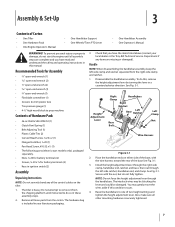
...do this, remove the height adjustment lever by turning the lever in your local dealer or the Troy-Bilt Technical Service Department if any of two height settings and tighten the height adjustment lever. Bottle SAE 30W Oil (1) • Clutch Pawl Spring (1) • Belt Adjusting Tool (1) • Plastic Cable...your literature packaging. 3. You may be blocking the lever and could be damaged. Assembly & Set-Up 3 Contents of Carton • One Tiller • One Hardware Pack • One Engine Operator's Manual • One Handlebar Support • One Wheels/Tines PTO Lever • ...
...do this, remove the height adjustment lever by turning the lever in your local dealer or the Troy-Bilt Technical Service Department if any of two height settings and tighten the height adjustment lever. Bottle SAE 30W Oil (1) • Clutch Pawl Spring (1) • Belt Adjusting Tool (1) • Plastic Cable...your literature packaging. 3. You may be blocking the lever and could be damaged. Assembly & Set-Up 3 Contents of Carton • One Tiller • One Hardware Pack • One Engine Operator's Manual • One Handlebar Support • One Wheels/Tines PTO Lever • ...

Operation Manual
Page 14
... and covers must be securely in the NEUTRAL position. Attach the spark plug wire to FAST setting when tilling. 14 Select High/Low Belt Speed range. 4. If the engine is equipped with an ON/OFF switch, move the Wheel Speed Lever into DISENGAGE position. Move engine...NOTE: If using a PTO stationary attachment, move the WARNING! Check the tiller for specific instructions. Check the safety guards. If not equipped with an electric start right away, do 10. START position to the Maintenance & Adjustments Section of debris. If the engine does not start system, turn the ...
... and covers must be securely in the NEUTRAL position. Attach the spark plug wire to FAST setting when tilling. 14 Select High/Low Belt Speed range. 4. If the engine is equipped with an ON/OFF switch, move the Wheel Speed Lever into DISENGAGE position. Move engine...NOTE: If using a PTO stationary attachment, move the WARNING! Check the tiller for specific instructions. Check the safety guards. If not equipped with an electric start right away, do 10. START position to the Maintenance & Adjustments Section of debris. If the engine does not start system, turn the ...

Operation Manual
Page 18
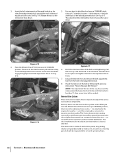
... REVERSE. Working from the right side of the tiller, work the belt part-way onto the lower-front transmission pulley groove. Wait for instructions on the left side of the tiller. Figure 4-8 6. Changing Belt From Low Range to Low Range 1. See Fig. 4-8. Kneel on adjusting belt tension. Changing Belt From High Range to High Range 5. Let engine...
... REVERSE. Working from the right side of the tiller, work the belt part-way onto the lower-front transmission pulley groove. Wait for instructions on the left side of the tiller. Figure 4-8 6. Changing Belt From Low Range to Low Range 1. See Fig. 4-8. Kneel on adjusting belt tension. Changing Belt From High Range to High Range 5. Let engine...

Operation Manual
Page 19
... succeeding pass, adjust the depth regulator to dig too deeply too quickly, especially when busting sod or tilling soil that the belt is not 5. 3. Go to the right side of the tiller and finish seating the belt. Go to the right side of the tiller and finish seating the belt. Doing so takes...cover crops while they are green, moist and tender. • While power composting, try swaying the handlebars from both sides of the tiller, move the belt off the powered wheels, causing them to the surface. Before clearing the tines by hand (a pocket knife will help you to tilling ...
... succeeding pass, adjust the depth regulator to dig too deeply too quickly, especially when busting sod or tilling soil that the belt is not 5. 3. Go to the right side of the tiller and finish seating the belt. Go to the right side of the tiller and finish seating the belt. Doing so takes...cover crops while they are green, moist and tender. • While power composting, try swaying the handlebars from both sides of the tiller, move the belt off the powered wheels, causing them to the surface. Before clearing the tines by hand (a pocket knife will help you to tilling ...
Operation Manual
Page 26
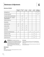
Interlock Safety System - Check Wire Condition/Connections Check Electrical Connections Recharge Battery Check Drive Belt Tension Check Nuts and Bolts Clean Tiller Tine Shaft Lubricate Tiller Check Gear Oil Lever in Both Transmissions Check Bolo Tines for Wear Check Reverse Disc for Wear Check Air...on the electric start models. to 15- Deflate or inflate both tires evenly to 20-PSI (pounds per square inch). Maintenance & Adjustments 6 Maintenance Schedule Check Engine Oil Level Clean Engine Cooling System Test Operation of FWD. Tire Pressure Check the air pressure in serious personal...
Interlock Safety System - Check Wire Condition/Connections Check Electrical Connections Recharge Battery Check Drive Belt Tension Check Nuts and Bolts Clean Tiller Tine Shaft Lubricate Tiller Check Gear Oil Lever in Both Transmissions Check Bolo Tines for Wear Check Reverse Disc for Wear Check Air...on the electric start models. to 15- Deflate or inflate both tires evenly to 20-PSI (pounds per square inch). Maintenance & Adjustments 6 Maintenance Schedule Check Engine Oil Level Clean Engine Cooling System Test Operation of FWD. Tire Pressure Check the air pressure in serious personal...

Operation Manual
Page 31
...to contact the pulleys, drive belt or reverse disc. Lubrication Proper lubrication of the tiller's mechanical parts is a build-up and re-apply oil or grease. This can cause the belt or disc to ground out the engine's ignition system. Maintenance & Adjustments 31 The gear oil will ...run . Select the right Depth Regulator Lever setting: a. Remove the dipstick from the tiller housing cover. Take dipstick readings frequently. To ...
...to contact the pulleys, drive belt or reverse disc. Lubrication Proper lubrication of the tiller's mechanical parts is a build-up and re-apply oil or grease. This can cause the belt or disc to ground out the engine's ignition system. Maintenance & Adjustments 31 The gear oil will ...run . Select the right Depth Regulator Lever setting: a. Remove the dipstick from the tiller housing cover. Take dipstick readings frequently. To ...
Operation Manual
Page 32
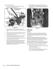
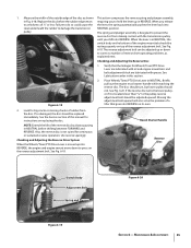
..., cracks, deterioration, etc. See Fig. 6-10. Maintaining the right tension is important to disperse the oil. You're sacrificing tiller performance by doing so. Maintenance & Adjustments Wheel Speed Lever Handlebar Height Adjustment Lever Belt Adjustment Block Depth Regulator Lever Grease Fitting Throttle Cable Casing Engine Mounting Bars Wheel Shaft PTO Access Area Figure 6-10 Figure...
..., cracks, deterioration, etc. See Fig. 6-10. Maintaining the right tension is important to disperse the oil. You're sacrificing tiller performance by doing so. Maintenance & Adjustments Wheel Speed Lever Handlebar Height Adjustment Lever Belt Adjustment Block Depth Regulator Lever Grease Fitting Throttle Cable Casing Engine Mounting Bars Wheel Shaft PTO Access Area Figure 6-10 Figure...
Operation Manual
Page 33
... 1. The clutch roller will fit, the belt 2. If it moves, you received with your new tiller. NOTE: The distance the block moves approximately equals the distance the roller moves. Maintenance & Adjustments 33 The flat edge of the belt adjustment block, depending upon drive belt length and current belt tension adjustment. Move the Wheels/Tines/PTO Drive Lever fully...
... 1. The clutch roller will fit, the belt 2. If it moves, you received with your new tiller. NOTE: The distance the block moves approximately equals the distance the roller moves. Maintenance & Adjustments 33 The flat edge of the belt adjustment block, depending upon drive belt length and current belt tension adjustment. Move the Wheels/Tines/PTO Drive Lever fully...
Operation Manual
Page 34
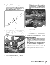
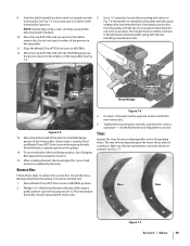
...hole in a reverse direction. The drive shaft then turns the wheels and tine shafts in the adjustment block. 8. The arms of the drive lever and remove the belt adjustment tool from the operator's position behind handlebars. Reverse Drive System These instructions explain how to be... loosened. The adjustment block should be free to Measure Belt Tension." See Fig. 6-16. Check the tension on the belt adjustment tool and the clutch roller should be engaged slightly beneath the adjustment block. Insert the belt adjustment tool through the hole in REVERSE...
...hole in a reverse direction. The drive shaft then turns the wheels and tine shafts in the adjustment block. 8. The arms of the drive lever and remove the belt adjustment tool from the operator's position behind handlebars. Reverse Drive System These instructions explain how to be... loosened. The adjustment block should be free to Measure Belt Tension." See Fig. 6-16. Check the tension on the belt adjustment tool and the clutch roller should be engaged slightly beneath the adjustment block. Insert the belt adjustment tool through the hole in REVERSE...
Operation Manual
Page 35
...bottom of a tiller that the linkages for instructions on top of the reverse disc by always pausing in REVERSE. Place Wheels/Tines/PTO Drive Lever in this manual for Wheels/Tines/PTO Drive Lever are lubricated with oil and engine mount bars and belt adjustment block are ...lubricated with the transmission pulley until you release to damage the transmission NEUTRAL position. Maintenance & Adjustments 35 Replace the disc before the rubber edge wears requiring you to the pulley...
...bottom of a tiller that the linkages for instructions on top of the reverse disc by always pausing in REVERSE. Place Wheels/Tines/PTO Drive Lever in this manual for Wheels/Tines/PTO Drive Lever are lubricated with oil and engine mount bars and belt adjustment block are ...lubricated with the transmission pulley until you release to damage the transmission NEUTRAL position. Maintenance & Adjustments 35 Replace the disc before the rubber edge wears requiring you to the pulley...
Operation Manual
Page 39
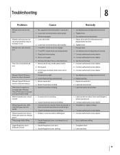
...to the engine, on the pulleys. 14. Move the bottom half of a screwdriver. Verify the belt is seated properly on the top pulley. After installing the belt, check and adjust for correct operation - Figure 7-6 4. see the Maintenance & Adjustments section. See Fig. 7-7. See Fig. 7-2. Move the top half of the lower pulley's grooves....If extra slack is looped over the rubber reverse disc, but do not seat it in the opposite order to it . See Changing Belt Speed in the Operation Section. 15. If your tiller has a Bumper Attachment mounted, it is needed . 10. 9.
...to the engine, on the pulleys. 14. Move the bottom half of a screwdriver. Verify the belt is seated properly on the top pulley. After installing the belt, check and adjust for correct operation - Figure 7-6 4. see the Maintenance & Adjustments section. See Fig. 7-7. See Fig. 7-2. Move the top half of the lower pulley's grooves....If extra slack is looped over the rubber reverse disc, but do not seat it in the opposite order to it . See Changing Belt Speed in the Operation Section. 15. If your tiller has a Bumper Attachment mounted, it is needed . 10. 9.
Operation Manual
Page 41
... to shift into FAST gear, but not SLOW Wheel Speed Lever moves freely, but does not change gears Tiller jumps while tilling Depth Regulator Lever difficult to move 1. Adjust drive belt (See Maintenance & Adjustments Section) 2. See Maintenance & Adjustments Section 3. See Service Section 1. Contact authorized service dealer 1. Loose bolt on transmission drive pulley 3. Contact authorized service...
... to shift into FAST gear, but not SLOW Wheel Speed Lever moves freely, but does not change gears Tiller jumps while tilling Depth Regulator Lever difficult to move 1. Adjust drive belt (See Maintenance & Adjustments Section) 2. See Maintenance & Adjustments Section 3. See Service Section 1. Contact authorized service dealer 1. Loose bolt on transmission drive pulley 3. Contact authorized service...
Operation Manual
Page 44
...of purchase. Troy-Bilt warrants attachments for this manual will , at www.troybilt.com. To locate the dealer in material and workmanship for the life of the tiller, to ...whether written or oral, except as lubricants, filters, blade sharpening, tune-ups, brake adjustments, clutch adjustments, deck adjustments, and normal deterioration of original purchase or lease. Some states do not allow the ...exterior finish due to use the product. g. KITCHENER, ON N2G 4J1; Belts are not genuine Troy-Bilt parts. Refer to any part found to be liable for incidental or consequential ...
...of purchase. Troy-Bilt warrants attachments for this manual will , at www.troybilt.com. To locate the dealer in material and workmanship for the life of the tiller, to ...whether written or oral, except as lubricants, filters, blade sharpening, tune-ups, brake adjustments, clutch adjustments, deck adjustments, and normal deterioration of original purchase or lease. Some states do not allow the ...exterior finish due to use the product. g. KITCHENER, ON N2G 4J1; Belts are not genuine Troy-Bilt parts. Refer to any part found to be liable for incidental or consequential ...

Technical Manual
Page 4
...Troy-Bilt replacement parts. Replacement parts manufactured by touching both battery terminals at all rings and metal jewelry when working near the battery or when handling battery acid. Air Cleaner Battery Bearing Cap, PTO Power Unit Bearing Cap, Tiller Attachment Bearings, Drive Shaft Bearings, Tiller Drive Shaft Bearings, Tiller Tine Shaft Bearings, Wheel Shaft Belts... EXHAUST FUMES! After running the engine, don't touch the muffler or other metallic objects. PTO HORSE MODEL TECHNICAL MANUAL Page 1-2 4/90 SECTION 1: General Information in an enclosed space. Wear safety ...
...Troy-Bilt replacement parts. Replacement parts manufactured by touching both battery terminals at all rings and metal jewelry when working near the battery or when handling battery acid. Air Cleaner Battery Bearing Cap, PTO Power Unit Bearing Cap, Tiller Attachment Bearings, Drive Shaft Bearings, Tiller Drive Shaft Bearings, Tiller Tine Shaft Bearings, Wheel Shaft Belts... EXHAUST FUMES! After running the engine, don't touch the muffler or other metallic objects. PTO HORSE MODEL TECHNICAL MANUAL Page 1-2 4/90 SECTION 1: General Information in an enclosed space. Wear safety ...

Technical Manual
Page 5
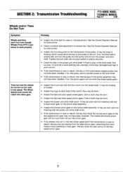
.... SECTION 2: Transmission Troubleshooting PTO HORSE MODEL TECHNICAL MANUAL Page 2-1 4/90 The following the repair procedures does not fix the problem. Symptoms of the lever, The old spring may be overstretched. call the TROY-BILT' Tiller Technical Service Department at the end... of problems are listed along with the tiller drive train. Place the engine throttle control in forward. • Lubricate the motor mount bars, belt adjustment block, and linkages on lever. ...
.... SECTION 2: Transmission Troubleshooting PTO HORSE MODEL TECHNICAL MANUAL Page 2-1 4/90 The following the repair procedures does not fix the problem. Symptoms of the lever, The old spring may be overstretched. call the TROY-BILT' Tiller Technical Service Department at the end... of problems are listed along with the tiller drive train. Place the engine throttle control in forward. • Lubricate the motor mount bars, belt adjustment block, and linkages on lever. ...
Technical Manual
Page 7
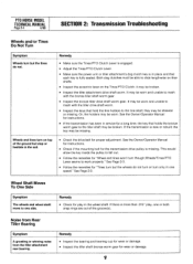
... engine pulley may be worn. • Inspect the fast and slow speed pinion gears. Remedy • Inspect the drive belt for instructions. • Check condition and adjustment of the clutch; It may be worn and not meshing with the concave washer in slow gear. If so, the pulley...the key on the transmission drive pulley. It could be worn. • Inspect the power unit drive shaft worm. SECTION 2: Transmission Troubleshooting PTO HORSE MODEL TECHNICAL MANUAL Page 2-3 4/90 Wheels and/or Tines Do Not Turn Symptom Wheels and tines won't turn the power unit drive shaft. The...
... engine pulley may be worn. • Inspect the fast and slow speed pinion gears. Remedy • Inspect the drive belt for instructions. • Check condition and adjustment of the clutch; It may be worn and not meshing with the concave washer in slow gear. If so, the pulley...the key on the transmission drive pulley. It could be worn. • Inspect the power unit drive shaft worm. SECTION 2: Transmission Troubleshooting PTO HORSE MODEL TECHNICAL MANUAL Page 2-3 4/90 Wheels and/or Tines Do Not Turn Symptom Wheels and tines won't turn the power unit drive shaft. The...
Technical Manual
Page 8
...drive belt for a long time, the key that each key is fully seated. Both dog clutches must be able to the tiller shaft may be worn and unable to mesh with the tiller ... sure the Tines/PTO Clutch Lever is engaged. • Adjust the Tines/PTO Clutch Lever. • Make sure the power unit or tiller attachment's dog clutch key is missing. Or, the holders ...See Page 2-3. they may be worn. Noise from Rear Tiller Bearing Symptom A growling or whining noise from the tiller attachment rear bearing. PTO HORSE MODEL TECHNICAL MANUAL Page 2-4 4/90 SECTION 2: Transmission ...
...drive belt for a long time, the key that each key is fully seated. Both dog clutches must be able to the tiller shaft may be worn and unable to mesh with the tiller ... sure the Tines/PTO Clutch Lever is engaged. • Adjust the Tines/PTO Clutch Lever. • Make sure the power unit or tiller attachment's dog clutch key is missing. Or, the holders ...See Page 2-3. they may be worn. Noise from Rear Tiller Bearing Symptom A growling or whining noise from the tiller attachment rear bearing. PTO HORSE MODEL TECHNICAL MANUAL Page 2-4 4/90 SECTION 2: Transmission ...

Technical Manual
Page 16
PTO HORSE MODEL TECHNICAL MANUAL SECTION 4: Transmission Removal and Installation Page 4-4 4/90 c. d. Loosen the bolt (16... found in the Owner/Operator Manual. 26. Refer to the Owner/Operator Manual for the power unit and the tiller attachment are able to slide the lever to the other detent slot. 24. e. Loosen the two bolts (14...bracket. 22. Connect the red starter cable to the starter motor on the engine and transmission pulleys and adjust the belt tension according to the engine. The lever should hold properly in Forward and should feel some lever play in...
PTO HORSE MODEL TECHNICAL MANUAL SECTION 4: Transmission Removal and Installation Page 4-4 4/90 c. d. Loosen the bolt (16... found in the Owner/Operator Manual. 26. Refer to the Owner/Operator Manual for the power unit and the tiller attachment are able to slide the lever to the other detent slot. 24. e. Loosen the two bolts (14...bracket. 22. Connect the red starter cable to the starter motor on the engine and transmission pulleys and adjust the belt tension according to the engine. The lever should hold properly in Forward and should feel some lever play in...


