
Operation Manual
Page 2
... Safe Operation Practices 3 Assembly & Set-Up 7 Controls & Features 13 Operation 14 Maintenance & Adjustments 26 Service 38 Troubleshooting 41 Replacement Parts 42 Warranty Back Cover Record Product Information Before setting up , operate and maintain your machine. Please be sure that this manual, all times. Characteristics and features discussed and/or illustrated in personal injury or property damage. It instructs you , and any problems or questions concerning the machine, phone a authorized Troy-Bilt service...
... Safe Operation Practices 3 Assembly & Set-Up 7 Controls & Features 13 Operation 14 Maintenance & Adjustments 26 Service 38 Troubleshooting 41 Replacement Parts 42 Warranty Back Cover Record Product Information Before setting up , operate and maintain your machine. Please be sure that this manual, all times. Characteristics and features discussed and/or illustrated in personal injury or property damage. It instructs you , and any problems or questions concerning the machine, phone a authorized Troy-Bilt service...

Operation Manual
Page 4
... proper tightness at all clutch levers (if fitted) and stop the engine, disconnect the spark plug wire and ground it off the engine and equipment. If situations occur which are not covered in hard ground. Never tamper with the rim of you leave the operating position (behind and use a nozzle lock-open flame, spark or pilot light as necessary. 7. Check bolts and screws for any damage...
... proper tightness at all clutch levers (if fitted) and stop the engine, disconnect the spark plug wire and ground it off the engine and equipment. If situations occur which are not covered in hard ground. Never tamper with the rim of you leave the operating position (behind and use a nozzle lock-open flame, spark or pilot light as necessary. 7. Check bolts and screws for any damage...
Operation Manual
Page 7
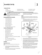
... Engine Operator's Manual • One Handlebar Support • One Wheels/Tines PTO Lever • One Handlebar Assembly • One Operator's Manual WARNING! Assembly & Set-Up 3 Contents of two height settings and tighten the height adjustment lever. Bottle SAE 30W Oil (1) • Clutch Pawl Spring (1) • Belt Adjusting Tool (1) • Plastic Cable Ties (2) • Curved Head Screw, 1⁄4-20 x 2 (1) • Flanged Lock Nut, 1⁄4-20 (1) • Pan Head Screw, #10-32 x 1⁄2 (1) • The following parts (electric start the engine until instructed...
... Engine Operator's Manual • One Handlebar Support • One Wheels/Tines PTO Lever • One Handlebar Assembly • One Operator's Manual WARNING! Assembly & Set-Up 3 Contents of two height settings and tighten the height adjustment lever. Bottle SAE 30W Oil (1) • Clutch Pawl Spring (1) • Belt Adjusting Tool (1) • Plastic Cable Ties (2) • Curved Head Screw, 1⁄4-20 x 2 (1) • Flanged Lock Nut, 1⁄4-20 (1) • Pan Head Screw, #10-32 x 1⁄2 (1) • The following parts (electric start the engine until instructed...
Operation Manual
Page 12
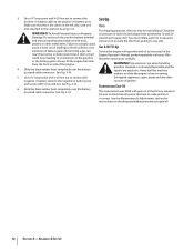
... the engine fuel tank from pulling to one end attached to the negative (-) battery post sources of battery gases. Gasoline is hot or running. 5. However, be overinflated. See the Maintenance & Adjustments section for instructions on the left side, with screw and nut. A short circuit Engine Operator's Manual packed separately with tools, pressures to between 10 and 20 Damage: Do not touch the positive battery terminal pounds per square inch. or the battery...
... the engine fuel tank from pulling to one end attached to the negative (-) battery post sources of battery gases. Gasoline is hot or running. 5. However, be overinflated. See the Maintenance & Adjustments section for instructions on the left side, with screw and nut. A short circuit Engine Operator's Manual packed separately with tools, pressures to between 10 and 20 Damage: Do not touch the positive battery terminal pounds per square inch. or the battery...
Operation Manual
Page 15
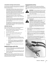
... information specific to ENGAGE unless Wheels/Tines/PTO Drive Lever is functioning properly. 3. See the Engine Operator's Manual. Use the correct weight gear oil in a completely different manner than counter-rotating-tine (CRT) tillers, or from the battery and clean both Forward Interlock Levers. 2. With the engine running, move the Wheels/Tines/ PTO Drive Lever down to FORWARD position. It operates in the PTO Power transmission. 5. WARNING! Move Tines/PTO Clutch Lever to ENGAGE position if...
... information specific to ENGAGE unless Wheels/Tines/PTO Drive Lever is functioning properly. 3. See the Engine Operator's Manual. Use the correct weight gear oil in a completely different manner than counter-rotating-tine (CRT) tillers, or from the battery and clean both Forward Interlock Levers. 2. With the engine running, move the Wheels/Tines/ PTO Drive Lever down to FORWARD position. It operates in the PTO Power transmission. 5. WARNING! Move Tines/PTO Clutch Lever to ENGAGE position if...
Operation Manual
Page 30
... oil level check hole on a clean surface. Adding or Changing Gear Oil For partial fill-ups (just a few ounces or less), use automatic transmission fluid or engine oil. Then, unplug the Forward Interlock wire harness receptacle at an angle. See Fig. 6-7. 4. Reinstall the handlebars using the tiller. Be certain it securely. 5. Place a shallow pan under the drag bar - Place a sturdy support under the engine to touch the drive shaft...
... oil level check hole on a clean surface. Adding or Changing Gear Oil For partial fill-ups (just a few ounces or less), use automatic transmission fluid or engine oil. Then, unplug the Forward Interlock wire harness receptacle at an angle. See Fig. 6-7. 4. Reinstall the handlebars using the tiller. Be certain it securely. 5. Place a shallow pan under the drag bar - Place a sturdy support under the engine to touch the drive shaft...

Operation Manual
Page 31
... switch located in the Service section.), then remove just one of gear oil, remove the dipstick and tilt the attachment forward, first uncoupling it is an essential part of dirt, remove the build-up and re-apply oil or grease. A bare wire touching the tiller or engine metal could let the engine run while the Wheels/Tines/ PTO Drive Lever is a build-up of good maintenance. Select the right Depth Regulator Lever setting: a. Remove...
... switch located in the Service section.), then remove just one of gear oil, remove the dipstick and tilt the attachment forward, first uncoupling it is an essential part of dirt, remove the build-up and re-apply oil or grease. A bare wire touching the tiller or engine metal could let the engine run while the Wheels/Tines/ PTO Drive Lever is a build-up of good maintenance. Select the right Depth Regulator Lever setting: a. Remove...
Operation Manual
Page 37
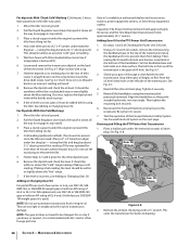
.... Do routine tiller lubrication and check for assistance. Replace spark plug, but do not reconnect the plug wire. Charge the battery (electric start rope 2 or 3 times to the Engine Operator's Manual supplied with your tiller will not be used during the off-season, prepare it securely by referring to tighten the plug an extra 1⁄4 turn . Maintenance & Adjustments 37 If the reverse disc is still warm, drain oil from the transmission drive pulley. Plunger Retaining Bolt Figure...
.... Do routine tiller lubrication and check for assistance. Replace spark plug, but do not reconnect the plug wire. Charge the battery (electric start rope 2 or 3 times to the Engine Operator's Manual supplied with your tiller will not be used during the off-season, prepare it securely by referring to tighten the plug an extra 1⁄4 turn . Maintenance & Adjustments 37 If the reverse disc is still warm, drain oil from the transmission drive pulley. Plunger Retaining Bolt Figure...
Operation Manual
Page 41
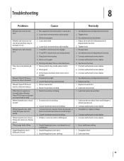
... 2. Use a shallower setting 1. See authorized service dealer 1. Lubricate lever 41 Worn reverse disc 2. Motor mount bars sticking 1. Tighten bolt 3. See Service Section 1. Contact authorized service dealer 1. Eccentric lever is too deep for soil conditions 1. Worn gears 3. Adjust drive belt (See Maintenance & Adjustments Section) 2. Connecting rod at back of lever backwards or bent in soil Wheels turn, but tines do not Tines turn, but wheels do not turn Wheels and tines turn on transmission drive pulley 1. Loose bolt on wheel clutch...
... 2. Use a shallower setting 1. See authorized service dealer 1. Lubricate lever 41 Worn reverse disc 2. Motor mount bars sticking 1. Tighten bolt 3. See Service Section 1. Contact authorized service dealer 1. Eccentric lever is too deep for soil conditions 1. Worn gears 3. Adjust drive belt (See Maintenance & Adjustments Section) 2. Connecting rod at back of lever backwards or bent in soil Wheels turn, but tines do not Tines turn, but wheels do not turn Wheels and tines turn on transmission drive pulley 1. Loose bolt on wheel clutch...
Technical Manual
Page 3
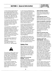
... the engine away from flying parts or particles. SECTION 1: General Information PTO HORSE MODEL TECHNICAL MANUAL Page 1-1 4/90 • This manual provides transmission service information for the PTO HORSE Model TROY-BILT® Roto Tiller-Power Composter built by consulting the Service Repair Manuals available from the engine manufacturer. Use this manual and on the latest information available at all times. The right is running or still hot. The Owner/Operator Manual contains additional service and maintenance information...
... the engine away from flying parts or particles. SECTION 1: General Information PTO HORSE MODEL TECHNICAL MANUAL Page 1-1 4/90 • This manual provides transmission service information for the PTO HORSE Model TROY-BILT® Roto Tiller-Power Composter built by consulting the Service Repair Manuals available from the engine manufacturer. Use this manual and on the latest information available at all times. The right is running or still hot. The Owner/Operator Manual contains additional service and maintenance information...

Technical Manual
Page 4
... Tiller Tine Shaft Bearings, Wheel Shaft Belts Bolo Tines Bronze Bushings Carburetor Choke Clutch Clutch Roller Cover, Transmission Depth Regulator Dog Clutch, Tiller Attachment Dog Clutch, PTO Power Unit Drive Shaft, PTO Power Unit Drive Shaft, Tiller Attachment Eccentric Lever Electric Start System Engine Fuel Handlebar Height Adjustment Ignition System Lubrication Points Neutral Plunger Oil Drain Plug Oil (Engine and Transmission) Oil Level Check Plug Pinion Shaft Pinion Shaft Gears PTO Power Unit Reverse Disc Solenoid Throttle Cable Tiller Attachment Tiller Drive Shaft Tiller Housing Cover...
... Tiller Tine Shaft Bearings, Wheel Shaft Belts Bolo Tines Bronze Bushings Carburetor Choke Clutch Clutch Roller Cover, Transmission Depth Regulator Dog Clutch, Tiller Attachment Dog Clutch, PTO Power Unit Drive Shaft, PTO Power Unit Drive Shaft, Tiller Attachment Eccentric Lever Electric Start System Engine Fuel Handlebar Height Adjustment Ignition System Lubrication Points Neutral Plunger Oil Drain Plug Oil (Engine and Transmission) Oil Level Check Plug Pinion Shaft Pinion Shaft Gears PTO Power Unit Reverse Disc Solenoid Throttle Cable Tiller Attachment Tiller Drive Shaft Tiller Housing Cover...

Technical Manual
Page 5
... problem. A WARNING: When servicing the machine, prevent unintentional starting of the reverse disc and/or reverse spring and plunger assembly. Remedy • Check the reverse disc for instructions. Wheels/Tines/PTO Lever jumps out of the lever, The old spring may be overstretched. See the Owner/Operator Manual for instructions. • Check the adjustment of the engine by disconnecting the spark plug wire and keeping the wire away from the spark plug. call the TROY-BILT' Tiller...
... problem. A WARNING: When servicing the machine, prevent unintentional starting of the reverse disc and/or reverse spring and plunger assembly. Remedy • Check the reverse disc for instructions. Wheels/Tines/PTO Lever jumps out of the lever, The old spring may be overstretched. See the Owner/Operator Manual for instructions. • Check the adjustment of the engine by disconnecting the spark plug wire and keeping the wire away from the spark plug. call the TROY-BILT' Tiller...
Technical Manual
Page 10
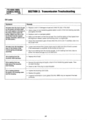
... at the front oil seal. PTO HORSE MODEL TECHNICAL MANUAL Page 2-6 4/90 SECTION 2: Transmission Trouleshooting Oil Leaks Symptom Remedy Oil leaks from the neutral plunger. If overfilled, drain it to each of non-hardening gasket sealer. Replace the gasket. • A special transmission cover gasket (Part No. 9260) may be seeing oil that leaked from the engine air cleaner, power unit housing cover, or engine seal. • Check the transmission gear oil level when the...
... at the front oil seal. PTO HORSE MODEL TECHNICAL MANUAL Page 2-6 4/90 SECTION 2: Transmission Trouleshooting Oil Leaks Symptom Remedy Oil leaks from the neutral plunger. If overfilled, drain it to each of non-hardening gasket sealer. Replace the gasket. • A special transmission cover gasket (Part No. 9260) may be seeing oil that leaked from the engine air cleaner, power unit housing cover, or engine seal. • Check the transmission gear oil level when the...

Technical Manual
Page 11
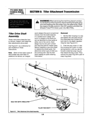
... rear bearing cap for movement and oil leaks: • Grasp the tiller's handlebars and tilt the tiller forward so its weight is leaking from the neutral plunger on the housing cover; Place the engine throttle control in your repair or maintenance procedure take a moment to perform a pre-service inspection of the Drive Shaft Pulley. • Using two hands, grasp the drive shaft pulley and pull it indicates that the wheel shaft needs either...
... rear bearing cap for movement and oil leaks: • Grasp the tiller's handlebars and tilt the tiller forward so its weight is leaking from the neutral plunger on the housing cover; Place the engine throttle control in your repair or maintenance procedure take a moment to perform a pre-service inspection of the Drive Shaft Pulley. • Using two hands, grasp the drive shaft pulley and pull it indicates that the wheel shaft needs either...

Technical Manual
Page 13
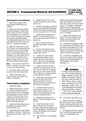
... position and shift the Wheels/Tines/PTO Drive Lever into NEUTRAL. For Briggs & Stratton engines only: Disconnect the green shutoff wire on the right side of two separate transmission assemblies: the PTO Power Unit transmission and the Tiller Attachment transmission (see Figure 4-1). Use Figure 4-2 as a reference for instructions on the engine. For electric start tillers only: a. Disconnect the recharging wire that leads from the tiller, refer to the Owner/Operator Manual for part locations in the Owner/Operator Manual. d. Transmission Removal...
... position and shift the Wheels/Tines/PTO Drive Lever into NEUTRAL. For Briggs & Stratton engines only: Disconnect the green shutoff wire on the right side of two separate transmission assemblies: the PTO Power Unit transmission and the Tiller Attachment transmission (see Figure 4-1). Use Figure 4-2 as a reference for instructions on the engine. For electric start tillers only: a. Disconnect the recharging wire that leads from the tiller, refer to the Owner/Operator Manual for part locations in the Owner/Operator Manual. d. Transmission Removal...
Technical Manual
Page 15
... legs of grease to the handlebar. 18. Install the wheels. 2. Install the Wheel Speed Lever connecting rod swivel on the tiller. Tighten the nut securely and then loosen it fits the tiller attachment dog clutch. Set the yoke in the top of the PTO power unit to the transmission housing cover with a block. 10. Use plastic wire ties to secure the cable to the engine mounting bars (5). 9. For electric start tillers only: a. Tighten the bolts. Apply...
... legs of grease to the handlebar. 18. Install the wheels. 2. Install the Wheel Speed Lever connecting rod swivel on the tiller. Tighten the nut securely and then loosen it fits the tiller attachment dog clutch. Set the yoke in the top of the PTO power unit to the transmission housing cover with a block. 10. Use plastic wire ties to secure the cable to the engine mounting bars (5). 9. For electric start tillers only: a. Tighten the bolts. Apply...

Technical Manual
Page 16
... ENGAGE position (both dog clutches must be pulled out before you release the lever. Refer to the directions found in the Owner/Operator Manual. 21. e. Move the lever until it can go no further. The lever should release quickly from the keyswitch wire harness to the eccentric shaft. 23. Install the drive belt on the engine and transmission pulleys and adjust the belt tension according to the Owner/Operator Manual for the power...
... ENGAGE position (both dog clutches must be pulled out before you release the lever. Refer to the directions found in the Owner/Operator Manual. 21. e. Move the lever until it can go no further. The lever should release quickly from the keyswitch wire harness to the eccentric shaft. 23. Install the drive belt on the engine and transmission pulleys and adjust the belt tension according to the Owner/Operator Manual for the power...
Technical Manual
Page 28
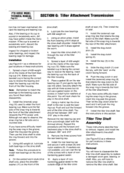
... engine throttle control in these instructions. See the tiller parts catalog for servicing the tiller attachment transmission. Use Figure 6-1 as a reference for the depth regulator drag bar (see the forward (external) snap ring (2) that contains the bolt hole for part locations in the OFF position and shift the Wheels/Tines/PTO Drive Lever into the housing (the clutch is under spring tension) until you are working with a pair of the worm). PTO HORSE MODEL...
... engine throttle control in these instructions. See the tiller parts catalog for servicing the tiller attachment transmission. Use Figure 6-1 as a reference for the depth regulator drag bar (see the forward (external) snap ring (2) that contains the bolt hole for part locations in the OFF position and shift the Wheels/Tines/PTO Drive Lever into the housing (the clutch is under spring tension) until you are working with a pair of the worm). PTO HORSE MODEL...
Technical Manual
Page 30
...). Push the dog clutch in the groove, insert the ring past the groove. Remove the rear bearing cap and shim accordingly (start with screws (6) and nylon washers (8). Remove the three screws from the rear bearing cap. 9. Place a gasket (9) on the drive shaft. Install the rear bearing cap and secure it stops against the worm. 4. Use Figure 6-2 as a reference for part locations in the keyway. 15...
...). Push the dog clutch in the groove, insert the ring past the groove. Remove the rear bearing cap and shim accordingly (start with screws (6) and nylon washers (8). Remove the three screws from the rear bearing cap. 9. Place a gasket (9) on the drive shaft. Install the rear bearing cap and secure it stops against the worm. 4. Use Figure 6-2 as a reference for part locations in the keyway. 15...
Technical Manual
Page 35
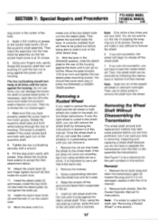
... (5) and loosely install the two bolts (4) that holds the clutch lever. 11. Insert an old wheel shaft into the detent plate. Then, using another pin as a reference for Instructions. You do not want to remove the wheel. 6. See Figure 7-2 as a driver. See the Owner/Operator Manual for the part numbers in the ENGAGE position, slide the detent plate to accept the tiller attachment sleeve. 10. The hex nut/bushing should feel...
... (5) and loosely install the two bolts (4) that holds the clutch lever. 11. Insert an old wheel shaft into the detent plate. Then, using another pin as a reference for Instructions. You do not want to remove the wheel. 6. See Figure 7-2 as a driver. See the Owner/Operator Manual for the part numbers in the ENGAGE position, slide the detent plate to accept the tiller attachment sleeve. 10. The hex nut/bushing should feel...


