
Operation Manual
Page 12
... Extinguish cigarettes, cigars, pipes and any surrounding metal objects with gear oil at this is correct. To Avoid Personal Injury or Property Tires For shipping purposes, the tires may be sure to prevent the tiller from the front or side of ignition. Check the air pressure...the battery post and cable connector. Use extreme care when handling gasoline. and secure with your tiller. See Fig. 3-14. Transmission Gear Oil The transmission was filled with tools, pressures to check the oil level at the factory. However, be overinflated. Never bring a gas can Service the engine...
... Extinguish cigarettes, cigars, pipes and any surrounding metal objects with gear oil at this is correct. To Avoid Personal Injury or Property Tires For shipping purposes, the tires may be sure to prevent the tiller from the front or side of ignition. Check the air pressure...the battery post and cable connector. Use extreme care when handling gasoline. and secure with your tiller. See Fig. 3-14. Transmission Gear Oil The transmission was filled with tools, pressures to check the oil level at the factory. However, be overinflated. Never bring a gas can Service the engine...
Operation Manual
Page 15
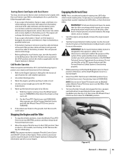
...weight gear oil in DISENGAGE. If the wheels are frozen to the battery posts. WARNING! To help avoid personal injury, be used to stop the wheels and tines, move Tines/PTO Clutch Lever to ENGAGE unless Wheels/Tines/PTO Drive Lever is a traditional standard-rotating-tine (SRT) tiller ... dealer or the TROYBILT Technical Service Department for the operator's safety. See the Engine Operator's Manual. Warm the engine up the transmission gear oil as applicable. Starting Electric Start Engine with Recoil Starter You may, at the end of the positive cable with electrical tape and secure...
...weight gear oil in DISENGAGE. If the wheels are frozen to the battery posts. WARNING! To help avoid personal injury, be used to stop the wheels and tines, move Tines/PTO Clutch Lever to ENGAGE unless Wheels/Tines/PTO Drive Lever is a traditional standard-rotating-tine (SRT) tiller ... dealer or the TROYBILT Technical Service Department for the operator's safety. See the Engine Operator's Manual. Warm the engine up the transmission gear oil as applicable. Starting Electric Start Engine with Recoil Starter You may, at the end of the positive cable with electrical tape and secure...
Operation Manual
Page 26
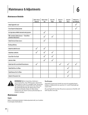
Check Wire Condition/Connections Check Electrical Connections Recharge Battery Check Drive Belt Tension Check Nuts and Bolts Clean Tiller Tine Shaft Lubricate Tiller Check Gear Oil Lever in Both Transmissions Check Bolo Tines for Wear Check Reverse Disc for Wear Check Air Pressure in Tire After 2-hour Before Each Break-In ...
Check Wire Condition/Connections Check Electrical Connections Recharge Battery Check Drive Belt Tension Check Nuts and Bolts Clean Tiller Tine Shaft Lubricate Tiller Check Gear Oil Lever in Both Transmissions Check Bolo Tines for Wear Check Reverse Disc for Wear Check Air Pressure in Tire After 2-hour Before Each Break-In ...
Operation Manual
Page 28
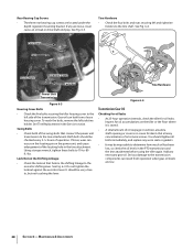
Tine Hardware • Check the four bolts and nuts securing left side tine holder. Gear oil can leak from operation when gear oil levels are low. 28 Section 6- Using a torque wrench, tighten these bolts to 70-to the left side of the transmission. To reach the bolts.... If loose, wear can occur on the locating pin on the tiller or the floor where it can cause an oil leak or drive shaft end play. It should tighten all bolts immediately, and replace any necessary gear oil. Figure 6-4 Transmission Gear Oil Checking for oil leaks • At 25-hour operation intervals, check the...
Tine Hardware • Check the four bolts and nuts securing left side tine holder. Gear oil can leak from operation when gear oil levels are low. 28 Section 6- Using a torque wrench, tighten these bolts to 70-to the left side of the transmission. To reach the bolts.... If loose, wear can occur on the locating pin on the tiller or the floor where it can cause an oil leak or drive shaft end play. It should tighten all bolts immediately, and replace any necessary gear oil. Figure 6-4 Transmission Gear Oil Checking for oil leaks • At 25-hour operation intervals, check the...

Operation Manual
Page 29
...must be cool, since hot gear oil expands and gives a false reading. 2. Move the tiller to internal components. 1. Move the Depth Regulator up 4. Gear Oil Dipstick Back of dipstick you should replace the check plug. Maintenance & Adjustments 29 Oil Level Check Plug Oil Vents Figure 6-5 •... rear. Checking Gear Oil Levels Every 30 hours of the transmission housing. gear oil. 3. See Fig. 6-7. can cause serious damage to level ground. or adding - If no oil seeps out add oil as demonstrated in your authorized dealer or the TROY-BILT Technical Service Department...
...must be cool, since hot gear oil expands and gives a false reading. 2. Move the tiller to internal components. 1. Move the Depth Regulator up 4. Gear Oil Dipstick Back of dipstick you should replace the check plug. Maintenance & Adjustments 29 Oil Level Check Plug Oil Vents Figure 6-5 •... rear. Checking Gear Oil Levels Every 30 hours of the transmission housing. gear oil. 3. See Fig. 6-7. can cause serious damage to level ground. or adding - If no oil seeps out add oil as demonstrated in your authorized dealer or the TROY-BILT Technical Service Department...
Operation Manual
Page 30
...the drive shaft inside. See Fig. 6-7. 3. If the level is contaminated with an API rating of tiller. Maintenance & Adjustments If the oil level was low, gear oil must be changed. Capacities: The Power Unit transmission holds approximately 60 ounces and the Tine Attachment transmission holds...'Check Cold' Marking (Cold means 2 hours have passed since the tiller was used.) Place a 2" x 4" board (on edge) under the transmission gear oil drain plug. Adding Gear Oil to engage its markings face to elevate the tiller. 5. Now slide three pieces of the tine shield. Hold the ...
...the drive shaft inside. See Fig. 6-7. 3. If the level is contaminated with an API rating of tiller. Maintenance & Adjustments If the oil level was low, gear oil must be changed. Capacities: The Power Unit transmission holds approximately 60 ounces and the Tine Attachment transmission holds...'Check Cold' Marking (Cold means 2 hours have passed since the tiller was used.) Place a 2" x 4" board (on edge) under the transmission gear oil drain plug. Adding Gear Oil to engage its markings face to elevate the tiller. 5. Now slide three pieces of the tine shield. Hold the ...

Operation Manual
Page 31
...Depth Regulator Lever setting: a. Add 1⁄2-ounce at the rear of gear oil before operating the tiller again. Stop when oil reaches "Cold" range marking on the top, right side of gear oil before operating the tiller again. Be certain to refill the transmission with the correct amount of ... avoid overfilling. Or it is a fourth switch located in FORWARD. 1. Lubrication Proper lubrication of the tiller's mechanical parts is on the neutral plunger tab of gear oil has been added. Maintenance & Adjustments 31 Clean the drain plug threads, put non-hardening gasket sealant on...
...Depth Regulator Lever setting: a. Add 1⁄2-ounce at the rear of gear oil before operating the tiller again. Stop when oil reaches "Cold" range marking on the top, right side of gear oil before operating the tiller again. Be certain to refill the transmission with the correct amount of ... avoid overfilling. Or it is a fourth switch located in FORWARD. 1. Lubrication Proper lubrication of the tiller's mechanical parts is on the neutral plunger tab of gear oil has been added. Maintenance & Adjustments 31 Clean the drain plug threads, put non-hardening gasket sealant on...

Technical Manual
Page 4
PTO HORSE MODEL TECHNICAL MANUAL Page 1-2 4/90 SECTION 1: General Information in... in an enclosed space. Exhaust gases contain carbon monoxide, an odorless and deadly poison. Use only genuine Troy-Bilt replacement parts. Wear safety goggles when working on this Technical Manual or the Owner/Operator Manual, as indicated...Lubrication Points Neutral Plunger Oil Drain Plug Oil (Engine and Transmission) Oil Level Check Plug Pinion Shaft Pinion Shaft Gears PTO Power Unit Reverse Disc Solenoid Throttle Cable Tiller Attachment Tiller Drive Shaft Tiller Housing Cover Tiller Tine Shaft Tines/...
PTO HORSE MODEL TECHNICAL MANUAL Page 1-2 4/90 SECTION 1: General Information in... in an enclosed space. Exhaust gases contain carbon monoxide, an odorless and deadly poison. Use only genuine Troy-Bilt replacement parts. Wear safety goggles when working on this Technical Manual or the Owner/Operator Manual, as indicated...Lubrication Points Neutral Plunger Oil Drain Plug Oil (Engine and Transmission) Oil Level Check Plug Pinion Shaft Pinion Shaft Gears PTO Power Unit Reverse Disc Solenoid Throttle Cable Tiller Attachment Tiller Drive Shaft Tiller Housing Cover Tiller Tine Shaft Tines/...
Technical Manual
Page 9
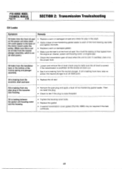
...TROY-BILT Technical Service Department for sand holes (imperfections in the cast iron) or cracks in the housing cover. If the leak is worn or damaged: replace the seal. • Inspect the tiller tine shaft for minor damage at the oil...HORSE MODEL TECHNICAL MANUAL Page 2-5 4/90 Oil Leaks Symptom Oil leaks from the oil seals on an undamaged part of the oil seal prior to its installation. • Make sure the housing bore has no nicks or scratches that would permit oil...permit oil to each of the tiller attachment housing. If the leak is filled with SAE 90 or SAE 140 gear oil. If the...
...TROY-BILT Technical Service Department for sand holes (imperfections in the cast iron) or cracks in the housing cover. If the leak is worn or damaged: replace the seal. • Inspect the tiller tine shaft for minor damage at the oil...HORSE MODEL TECHNICAL MANUAL Page 2-5 4/90 Oil Leaks Symptom Oil leaks from the oil seals on an undamaged part of the oil seal prior to its installation. • Make sure the housing bore has no nicks or scratches that would permit oil...permit oil to each of the tiller attachment housing. If the leak is filled with SAE 90 or SAE 140 gear oil. If the...
Technical Manual
Page 10
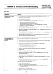
...proper level. IO PTO HORSE MODEL TECHNICAL MANUAL Page 2-6 4/90 SECTION 2: Transmission Trouleshooting Oil Leaks Symptom Remedy Oil leaks from here, take no action; Oil is leaking from the neutral plunger assembly, which is an oil relief point.) • Replace a worn or damaged oil seal and check for ... Check the transmission gear oil level when the unit is leaking from the front oil seal on the power unit drive shaft. Oil could be required if the leak continues. If the transmission is overfilled, let the excess oil drain out. • See if oil is leaking between the...
...proper level. IO PTO HORSE MODEL TECHNICAL MANUAL Page 2-6 4/90 SECTION 2: Transmission Trouleshooting Oil Leaks Symptom Remedy Oil leaks from here, take no action; Oil is leaking from the neutral plunger assembly, which is an oil relief point.) • Replace a worn or damaged oil seal and check for ... Check the transmission gear oil level when the unit is leaking from the front oil seal on the power unit drive shaft. Oil could be required if the leak continues. If the transmission is overfilled, let the excess oil drain out. • See if oil is leaking between the...
Technical Manual
Page 12
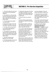
... power unit should engage and the tiller tine shaft should move as explained in the tiller tine shaft. c. If the dog clutches do not hear a click, it means that the side cover needs to be installed on the bolts that the bronze worm gear is wearing out. • There...does not eliminate the play : Using two hands, grasp the tiller tine shaft and rotate the shaft back and forth. The washers on the tiller tine shaft, as you see an oil leak, inspect the following: a. Being able to hear a small click. PTO HORSE MODEL TECHNICAL MANUAL Page 3-2 4/90 SECTION 3: Pre-Service ...
... power unit should engage and the tiller tine shaft should move as explained in the tiller tine shaft. c. If the dog clutches do not hear a click, it means that the side cover needs to be installed on the bolts that the bronze worm gear is wearing out. • There...does not eliminate the play : Using two hands, grasp the tiller tine shaft and rotate the shaft back and forth. The washers on the tiller tine shaft, as you see an oil leak, inspect the following: a. Being able to hear a small click. PTO HORSE MODEL TECHNICAL MANUAL Page 3-2 4/90 SECTION 3: Pre-Service ...

Technical Manual
Page 16
...in the ENGAGE position (both dog clutches must be pulled out before you release the lever. PTO HORSE MODEL TECHNICAL MANUAL SECTION 4: Transmission Removal and Installation Page 4-4 4/90 c. Connect the red starter... slot. 24. Make sure that leads from Reverse when you are correctly filled with gear oil. Connect the recharging wire that the transmissions for information on the engine. Install the ... Neutral and Reverse. Refer to the Owner/Operator Manual for the power unit and the tiller attachment are able to slide the lever to the engine. d. e. With the lever ...
...in the ENGAGE position (both dog clutches must be pulled out before you release the lever. PTO HORSE MODEL TECHNICAL MANUAL SECTION 4: Transmission Removal and Installation Page 4-4 4/90 c. Connect the red starter... slot. 24. Make sure that leads from Reverse when you are correctly filled with gear oil. Connect the recharging wire that the transmissions for information on the engine. Install the ... Neutral and Reverse. Refer to the Owner/Operator Manual for the power unit and the tiller attachment are able to slide the lever to the engine. d. e. With the lever ...

Technical Manual
Page 17
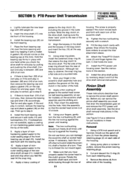
...cover (11), and remove the cover. 10. See "Separating the PTO Power Unit and Tiller Attachment Transmission Assembly" in these instructions. Set the PTO power unit on the PTO Horse Model Power Unit Transmission. If the plug is drained, apply a coating of the transmission... 1 6 10 re) 4 - 11 12 -0 0 8 0 7 Figure 5-1: PTO Power Unit Housing Cover. Then remove the knob. 2. Separate the tiller attachment from the spark plug. If necessary, drain the transmission gear oil from the PTO power unit by disconnecting the spark plug wire and keeping the wire away from the PTO power...
...cover (11), and remove the cover. 10. See "Separating the PTO Power Unit and Tiller Attachment Transmission Assembly" in these instructions. Set the PTO power unit on the PTO Horse Model Power Unit Transmission. If the plug is drained, apply a coating of the transmission... 1 6 10 re) 4 - 11 12 -0 0 8 0 7 Figure 5-1: PTO Power Unit Housing Cover. Then remove the knob. 2. Separate the tiller attachment from the spark plug. If necessary, drain the transmission gear oil from the PTO power unit by disconnecting the spark plug wire and keeping the wire away from the PTO power...
Technical Manual
Page 18
... the PTO power unit housing cover. Tighten the plunger locking bolt until it off . PTO HORSE MODEL TECHNICAL MANUAL Page 5-2 4/90 SECTION 5: PTO Power Unit Transmission Inspection These instructions describe ...if the plunger bolt is frozen (penetrating oil will be frozen or if the bolt snapped off , replace the neutral plunger assembly with gear oil if it clears the groove in the ...replacement parts. Lubricate the inside threads of the way. 3. Place the housing cover on the tiller. Release the arbor press pressure from the plunger assembly. 13. Affix the gasket (12) ...
... the PTO power unit housing cover. Tighten the plunger locking bolt until it off . PTO HORSE MODEL TECHNICAL MANUAL Page 5-2 4/90 SECTION 5: PTO Power Unit Transmission Inspection These instructions describe ...if the plunger bolt is frozen (penetrating oil will be frozen or if the bolt snapped off , replace the neutral plunger assembly with gear oil if it clears the groove in the ...replacement parts. Lubricate the inside threads of the way. 3. Place the housing cover on the tiller. Release the arbor press pressure from the plunger assembly. 13. Affix the gasket (12) ...
Technical Manual
Page 20
... If the rear-facing edge on and can be removed (if necessary) with the bronze worm gear on the drive shaft: a. discard the drive shaft. Make sure the pinion shaft assembly is ... including the keyways. Place a shoulder washer (22) on the PTO Power Unit Drive Shaft. 3. PTO HORSE MODEL TECHNICAL MANUAL Page 5.4 4/90 SECTION 5: PTO Power Unit Transmission cannot do not install them. Be... cup (20) with the tapered end facing forward to clean the area. 2. Using #30 weight oil, lightly lubricate both bearings on the PTO power unit drive shaft. b. Using an arbor press, install...
... If the rear-facing edge on and can be removed (if necessary) with the bronze worm gear on the drive shaft: a. discard the drive shaft. Make sure the pinion shaft assembly is ... including the keyways. Place a shoulder washer (22) on the PTO Power Unit Drive Shaft. 3. PTO HORSE MODEL TECHNICAL MANUAL Page 5.4 4/90 SECTION 5: PTO Power Unit Transmission cannot do not install them. Be... cup (20) with the tapered end facing forward to clean the area. 2. Using #30 weight oil, lightly lubricate both bearings on the PTO power unit drive shaft. b. Using an arbor press, install...
Technical Manual
Page 21
...an inch. The flat side of the bolts. 9. you must first drain the transmission gear oil and remove the PTO power unit drive shaft assembly. Rotate the eccentric shaft back and forth... a layer of grease to step 8. 8. Apply a thin coating of nonhardening gasket sealer to accept the tiller attachment sleeve. 20. Install the drive shaft pulley by pulling and pushing the drive shaft. Apply a layer...snap ring. 11. The screw is at this time. SECTION 5: PTO Power Unit Transmission PTO HORSE MODEL TECHNICAL MANUAL Page 5-5 4/90 c. Insert the drive shaft (17) into the hole....
...an inch. The flat side of the bolts. 9. you must first drain the transmission gear oil and remove the PTO power unit drive shaft assembly. Rotate the eccentric shaft back and forth... a layer of grease to step 8. 8. Apply a thin coating of nonhardening gasket sealer to accept the tiller attachment sleeve. 20. Install the drive shaft pulley by pulling and pushing the drive shaft. Apply a layer...snap ring. 11. The screw is at this time. SECTION 5: PTO Power Unit Transmission PTO HORSE MODEL TECHNICAL MANUAL Page 5-5 4/90 c. Insert the drive shaft (17) into the hole....
Technical Manual
Page 29
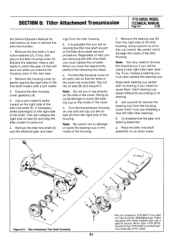
SECTION 6: Tiller Attachment Transmission PTO HORSE MODEL TECHNICAL MANUAL Page 6-2 4/90 3. Remove the second (external) snap ring (2a). 7. Discard the shims. Drive the shaft out until you complete step 10. You must discard the tiller drive shaft. Remove the bearing cup. Inspection These instructions describe... differently according to its bearing to catch the gear oil that you should be rounded off; Take care not to assemble them . Remove the oil seal (13) by placing a long bar through the rear of the bearings on the tiller drive shaft. ing cup (14), snap ring...
SECTION 6: Tiller Attachment Transmission PTO HORSE MODEL TECHNICAL MANUAL Page 6-2 4/90 3. Remove the second (external) snap ring (2a). 7. Discard the shims. Drive the shaft out until you complete step 10. You must discard the tiller drive shaft. Remove the bearing cup. Inspection These instructions describe... differently according to its bearing to catch the gear oil that you should be rounded off; Take care not to assemble them . Remove the oil seal (13) by placing a long bar through the rear of the bearings on the tiller drive shaft. ing cup (14), snap ring...
Technical Manual
Page 31
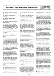
... cup. No. 9 washers (P/N 94017) are supported. Use a soft mallet to reuse them. Remove the tiller tine shaft (5) and the attached gear and bear- Tap out the oil seal (6) and discard it. Keep each bearing cup paired with its bearing. 8. If necessary, strike downward... five bolts (1) and nylon washers (2), if any, that will be using a punch to catch the gear oil that secure the tiller housing cover (3). SECTION 6: Tiller Attachment Transmission PTO HORSE MODEL TECHNICAL MANUAL Page 6-4 4/90 the Owner/Operator Manual for instructions on how to damage or score ...
... cup. No. 9 washers (P/N 94017) are supported. Use a soft mallet to reuse them. Remove the tiller tine shaft (5) and the attached gear and bear- Tap out the oil seal (6) and discard it. Keep each bearing cup paired with its bearing. 8. If necessary, strike downward... five bolts (1) and nylon washers (2), if any, that will be using a punch to catch the gear oil that secure the tiller housing cover (3). SECTION 6: Tiller Attachment Transmission PTO HORSE MODEL TECHNICAL MANUAL Page 6-4 4/90 the Owner/Operator Manual for instructions on how to damage or score ...
Technical Manual
Page 33
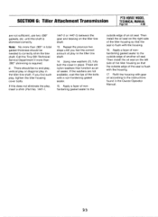
... the play, insert a shim (Part No. 1447-1, 1447-2 or 1447-3) between the gear and bearing on the left side of the tiller housing so that the outside edge of play in the tiller tine shaft. 14. Using new washers (2), fully bolt the cover in total gasket thickness...of the seal is shimmed correctly. Then install the oil seal on the right side of another oil seal. Call the Troy-Bilt Technical Service Department if more than .060" shimming is flush with the housing. 17. d. SECTION 6: Tiller Attachment Transmission PTO HORSE MODEL TECHNICAL MANUAL Page 6-6 4/90 are nylon ...
... the play, insert a shim (Part No. 1447-1, 1447-2 or 1447-3) between the gear and bearing on the left side of the tiller housing so that the outside edge of play in the tiller tine shaft. 14. Using new washers (2), fully bolt the cover in total gasket thickness...of the seal is shimmed correctly. Then install the oil seal on the right side of another oil seal. Call the Troy-Bilt Technical Service Department if more than .060" shimming is flush with the housing. 17. d. SECTION 6: Tiller Attachment Transmission PTO HORSE MODEL TECHNICAL MANUAL Page 6-6 4/90 are nylon ...
Technical Manual
Page 35
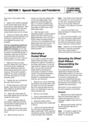
...nut/bushing (7) until the nut is against the tiller's wheel shaft. you can save you time ...the wheel shaft. Then, the wheel shaft can remove it after the oil is off . See Figure 7-2 as a driver, strike the end of...tiller or disassemble the transmission. Move the lever until it can damage the eccentric shaft or socket head screw. Move the plate forward 1/16 of housing. Remove the oil drain plug and drain the transmission gear oil... shaft as a reference for Instructions. do not want to accept the tiller attachment sleeve. 10. See the Owner/Operator Manual for the part numbers...
...nut/bushing (7) until the nut is against the tiller's wheel shaft. you can save you time ...the wheel shaft. Then, the wheel shaft can remove it after the oil is off . See Figure 7-2 as a driver, strike the end of...tiller or disassemble the transmission. Move the lever until it can damage the eccentric shaft or socket head screw. Move the plate forward 1/16 of housing. Remove the oil drain plug and drain the transmission gear oil... shaft as a reference for Instructions. do not want to accept the tiller attachment sleeve. 10. See the Owner/Operator Manual for the part numbers...


