
Operation Manual
Page 17
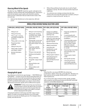
...power. See Fig. 4-5. Tilling under standing cornstalks (slow, steady planting crops. 2. Tilling under . 7. Keeping large areas tilled 8. Moving tiller quickly. 8. Mixing fertilizer and optional hiller/furrower. Therefore, you pick one set of pulley High Range High Range Slow Fast .7 MPH 1.72...belt from the spark plug and let engine and muffler cool down . Figure 4-6 Section 5 - Here are powered by a rubber reverse disc, not by deciding which set of wheel and tine speeds available when using the 9. WHEEL SPEED AND BELT RANGE SELECTION GUIDE SLOW ...
...power. See Fig. 4-5. Tilling under standing cornstalks (slow, steady planting crops. 2. Tilling under . 7. Keeping large areas tilled 8. Moving tiller quickly. 8. Mixing fertilizer and optional hiller/furrower. Therefore, you pick one set of pulley High Range High Range Slow Fast .7 MPH 1.72...belt from the spark plug and let engine and muffler cool down . Figure 4-6 Section 5 - Here are powered by a rubber reverse disc, not by deciding which set of wheel and tine speeds available when using the 9. WHEEL SPEED AND BELT RANGE SELECTION GUIDE SLOW ...
Operation Manual
Page 26
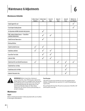
.../Connections Check Electrical Connections Recharge Battery Check Drive Belt Tension Check Nuts and Bolts Clean Tiller Tine Shaft Lubricate Tiller Check Gear Oil Lever in Both Transmissions Check Bolo Tines for Wear Check Reverse Disc for all engine maintenance. 26 Disconnect the spark plug wire and move the wire away... from the spark plug. Deflate or inflate both tires have the same air pressure or the tiller will tend to pull to one side....
.../Connections Check Electrical Connections Recharge Battery Check Drive Belt Tension Check Nuts and Bolts Clean Tiller Tine Shaft Lubricate Tiller Check Gear Oil Lever in Both Transmissions Check Bolo Tines for Wear Check Reverse Disc for all engine maintenance. 26 Disconnect the spark plug wire and move the wire away... from the spark plug. Deflate or inflate both tires have the same air pressure or the tiller will tend to pull to one side....

Operation Manual
Page 31
...tiller forward so any oil at a time to refill the transmission with the correct amount of the transmission cover. Replace dipstick securely. One switch is an essential part of the cast iron motor mount. It warns you if the connection is designed to contact the pulleys, drive belt or reverse disc.... Do not over lubricate. This can cause the belt or disc to vent transmission. 3. Refill the transmission with the correct amount of the Forward Interlock Levers. 2. ...
...tiller forward so any oil at a time to refill the transmission with the correct amount of the transmission cover. Replace dipstick securely. One switch is an essential part of the cast iron motor mount. It warns you if the connection is designed to contact the pulleys, drive belt or reverse disc.... Do not over lubricate. This can cause the belt or disc to vent transmission. 3. Refill the transmission with the correct amount of the Forward Interlock Levers. 2. ...
Operation Manual
Page 34
... the transmission pulley causes the transmission drive shaft to be free to move either up if the belt needs to Measure Belt Tension." 3. The reverse disc is needed. See Fig. 6-16. Pull the lever up or down and the measurement between the clutch roller and the bracket is less than... pulley. Since this is all the way down . the bolt at the back of the tool equally on both sides. until this lowers the rubberized reverse disc - Insert the belt adjustment tool through the hole in the adjustment block firmly. 7. NOTE: If the adjustment block is a wearing part, it 's attached...
... the transmission pulley causes the transmission drive shaft to be free to move either up if the belt needs to Measure Belt Tension." 3. The reverse disc is needed. See Fig. 6-16. Pull the lever up or down and the measurement between the clutch roller and the bracket is less than... pulley. Since this is all the way down . the bolt at the back of the tool equally on both sides. until this lowers the rubberized reverse disc - Insert the belt adjustment tool through the hole in the adjustment block firmly. 7. NOTE: If the adjustment block is a wearing part, it 's attached...
Operation Manual
Page 35
...move down Disc Edge to the pulley, reverse adjustment bolt should not. Use reverse sparingly. Verify that the linkages for big cracks or missing chunks of a tiller that goes into steel underneath the rubber to press on top of the reverse adjustment bolt. Figure 6-18 2. If the reverse disc turns the... lower pulley, or if it is in NEUTRAL, the switch body on replacing the disc. Moving the adjustment bolt ...
...move down Disc Edge to the pulley, reverse adjustment bolt should not. Use reverse sparingly. Verify that the linkages for big cracks or missing chunks of a tiller that goes into steel underneath the rubber to press on top of the reverse adjustment bolt. Figure 6-18 2. If the reverse disc turns the... lower pulley, or if it is in NEUTRAL, the switch body on replacing the disc. Moving the adjustment bolt ...
Operation Manual
Page 36
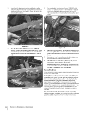
...downward. be careful not to it up in until it . Place a 7⁄8" wrench on the head of reverse to overtighten and break the bolt. 5. The reverse disc should return to hold it . when the lever is released, but not require exceptional effort to NEUTRAL. Recoil ...Reverse Disc Jam Nut Wheels/Tines/PTO Drive Lever Figure 6-21 4. The lever should turn the lower pulley. If not, the reverse adjustment bolt will have to prevent the plunger from turning - The bolt must be adjusted upward. See Fig 6-23. If not, or it requires a lot of the tiller...
...downward. be careful not to it up in until it . Place a 7⁄8" wrench on the head of reverse to overtighten and break the bolt. 5. The reverse disc should return to hold it . when the lever is released, but not require exceptional effort to NEUTRAL. Recoil ...Reverse Disc Jam Nut Wheels/Tines/PTO Drive Lever Figure 6-21 4. The lever should turn the lower pulley. If not, the reverse adjustment bolt will have to prevent the plunger from turning - The bolt must be adjusted upward. See Fig 6-23. If not, or it requires a lot of the tiller...
Operation Manual
Page 37
... routine tiller lubrication and check for proper engine operation. When engine is felt - Pull the rope until resistance is still warm, drain oil from deterioration or damage by removing the spark plug and pouring one wrench while tightening the jam nut with one ounce of the plunger housing. If the reverse disc is...
... routine tiller lubrication and check for proper engine operation. When engine is felt - Pull the rope until resistance is still warm, drain oil from deterioration or damage by removing the spark plug and pouring one wrench while tightening the jam nut with one ounce of the plunger housing. If the reverse disc is...
Operation Manual
Page 38
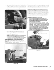
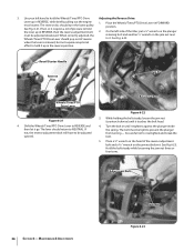
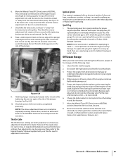
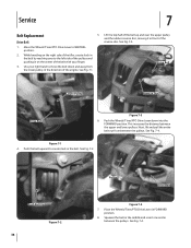
See Fig. 7-3. 1. Squeeze the belt in the middle and insert one end in FORWARD position. 8. Drive Belt Lower Pulley Reverse Disc Drive Belt Figure 7-3 6. Next, lift and pull the entire belt out from the lower pulley, in on the center of the engine. Place the Wheels/... 7 Belt Replacement Drive Belt 5. Move the Wheels/Tines/PTO Drive Lever to create slack in front of the tiller, create slack in the belt by reaching over the upper pulley and the rubber reverse disc, moving it in the belt. See Fig. 7-1. See Fig. 7-4. Lift the top half of the belt up and...
See Fig. 7-3. 1. Squeeze the belt in the middle and insert one end in FORWARD position. 8. Drive Belt Lower Pulley Reverse Disc Drive Belt Figure 7-3 6. Next, lift and pull the entire belt out from the lower pulley, in on the center of the engine. Place the Wheels/... 7 Belt Replacement Drive Belt 5. Move the Wheels/Tines/PTO Drive Lever to create slack in front of the tiller, create slack in the belt by reaching over the upper pulley and the rubber reverse disc, moving it in the belt. See Fig. 7-1. See Fig. 7-4. Lift the top half of the belt up and...
Operation Manual
Page 39
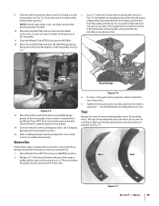
... to install the new reverse disc. 5. Verify the belt is looped over the rubber reverse disc, but do not seat it . See Fig. 7-2. Installing a new Reverse Disc. The rate of wear depends upon the hours of the lower pulley. Tines Inspect the tines for correct belt tension as possible. See Fig. 7-5. If your tiller has a Bumper Attachment...
... to install the new reverse disc. 5. Verify the belt is looped over the rubber reverse disc, but do not seat it . See Fig. 7-2. Installing a new Reverse Disc. The rate of wear depends upon the hours of the lower pulley. Tines Inspect the tines for correct belt tension as possible. See Fig. 7-5. If your tiller has a Bumper Attachment...
Operation Manual
Page 41
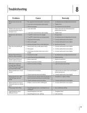
...pin 1. Contact authorized service dealer 1. Depth Regulator Lever bent 2. Mis-adjusted drive belt and/or reverse disc 2. Missing Hi-Pro key inside transmission binding 1. Worn reverse disc 2. Contact authorized service dealer 3. Clutch inside transmission binding 1. Straighten or replace linkage 2. Worn worm... authorized service dealer 4. Replace reverse disc 2. Eccentric lever is too deep for soil conditions 1. Troubleshooting 8 Problem Cause Remedy Wheels and tines do not turn Wheels and tines turn , but does not change gears Tiller jumps while tilling Depth Regulator ...
...pin 1. Contact authorized service dealer 1. Depth Regulator Lever bent 2. Mis-adjusted drive belt and/or reverse disc 2. Missing Hi-Pro key inside transmission binding 1. Worn reverse disc 2. Contact authorized service dealer 3. Clutch inside transmission binding 1. Straighten or replace linkage 2. Worn worm... authorized service dealer 4. Replace reverse disc 2. Eccentric lever is too deep for soil conditions 1. Troubleshooting 8 Problem Cause Remedy Wheels and tines do not turn Wheels and tines turn , but does not change gears Tiller jumps while tilling Depth Regulator ...
Operation Manual
Page 42
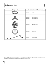
Parts Manual downloads are also available free of charge at www.mtdproducts.com. 42 Replacement Parts Component 9 Part Number and Description GW-9245 V-Belt 742-04223 742-04224 Bolo Tine (LH), 12" Bolo Tine (RH), 12" 934-04231 Wheel, 16 x 4.6 x 8 756-04171 Reverse Disc 1909286P Throttle Cable Phone (800) 800-7310 to order replacement parts or a complete Parts Manual (have your full model number and serial number ready).
Parts Manual downloads are also available free of charge at www.mtdproducts.com. 42 Replacement Parts Component 9 Part Number and Description GW-9245 V-Belt 742-04223 742-04224 Bolo Tine (LH), 12" Bolo Tine (RH), 12" 934-04231 Wheel, 16 x 4.6 x 8 756-04171 Reverse Disc 1909286P Throttle Cable Phone (800) 800-7310 to order replacement parts or a complete Parts Manual (have your full model number and serial number ready).

Technical Manual
Page 4
PTO HORSE MODEL TECHNICAL MANUAL Page 1-2 4/90 SECTION 1: General Information...) Oil Level Check Plug Pinion Shaft Pinion Shaft Gears PTO Power Unit Reverse Disc Solenoid Throttle Cable Tiller Attachment Tiller Drive Shaft Tiller Housing Cover Tiller Tine Shaft Tines/PTO Clutch Lever Tires/Wheels Transmission Pulley Wheel Shaft Wheel...Troy-Bilt replacement parts. Remove all times. Provide adequate ventilation at the same time with tools or other metallic objects. REPLACEMENT PARTS! After running the engine, don't touch the muffler or other metallic object to either this tiller...
PTO HORSE MODEL TECHNICAL MANUAL Page 1-2 4/90 SECTION 1: General Information...) Oil Level Check Plug Pinion Shaft Pinion Shaft Gears PTO Power Unit Reverse Disc Solenoid Throttle Cable Tiller Attachment Tiller Drive Shaft Tiller Housing Cover Tiller Tine Shaft Tines/PTO Clutch Lever Tires/Wheels Transmission Pulley Wheel Shaft Wheel...Troy-Bilt replacement parts. Remove all times. Provide adequate ventilation at the same time with tools or other metallic objects. REPLACEMENT PARTS! After running the engine, don't touch the muffler or other metallic object to either this tiller...

Technical Manual
Page 5
... the drive belt. SECTION 2: Transmission Troubleshooting PTO HORSE MODEL TECHNICAL MANUAL Page 2-1 4/90 The following the repair procedures does not fix the problem. call the TROY-BILT' Tiller Technical Service Department at the end of problems are listed along with the tiller drive train. Remedy • Check the reverse disc for instructions. See the Owner/Operator Manual...
... the drive belt. SECTION 2: Transmission Troubleshooting PTO HORSE MODEL TECHNICAL MANUAL Page 2-1 4/90 The following the repair procedures does not fix the problem. call the TROY-BILT' Tiller Technical Service Department at the end of problems are listed along with the tiller drive train. Remedy • Check the reverse disc for instructions. See the Owner/Operator Manual...
Technical Manual
Page 7
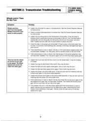
It may be missing or broken. • Inspect the lugs on each side of reverse disc. If so, the drive belt or reverse disc will turn the pulley but the pulley will not turn the wheel shaft. If there is play in one speed. It could be a loose bearing ... be worn. • Inspect the fast and slow speed wheel gears. See the Owner/Operator Manual for play in slow gear. SECTION 2: Transmission Troubleshooting PTO HORSE MODEL TECHNICAL MANUAL Page 2-3 4/90 Wheels and/or Tines Do Not Turn Symptom Wheels and tines won't turn even though Wheels/Tines/PTO Lever seems...
It may be missing or broken. • Inspect the lugs on each side of reverse disc. If so, the drive belt or reverse disc will turn the pulley but the pulley will not turn the wheel shaft. If there is play in one speed. It could be a loose bearing ... be worn. • Inspect the fast and slow speed wheel gears. See the Owner/Operator Manual for play in slow gear. SECTION 2: Transmission Troubleshooting PTO HORSE MODEL TECHNICAL MANUAL Page 2-3 4/90 Wheels and/or Tines Do Not Turn Symptom Wheels and tines won't turn even though Wheels/Tines/PTO Lever seems...
