
Operation Manual
Page 7
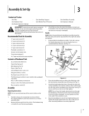
... clamp, handlebar end, ratchet, and base; Bottle SAE 30W Oil (1) • Clutch Pawl Spring (1) • Belt Adjusting Tool (1) • Plastic Cable Ties (2) • Curved Head Screw, 1⁄4-20 x 2 (1) •...8226; Tire pressure gauge (1) • 4-1⁄2" high wood block to one of Carton • One Tiller • One Hardware Pack • One Engine Operator's Manual • One Handlebar Support • One .... Check that you have the items listed above (contact your local dealer or the Troy-Bilt Technical Service Department if any of the base See Fig. 3-1. 3. Assembly & Set...
... clamp, handlebar end, ratchet, and base; Bottle SAE 30W Oil (1) • Clutch Pawl Spring (1) • Belt Adjusting Tool (1) • Plastic Cable Ties (2) • Curved Head Screw, 1⁄4-20 x 2 (1) •...8226; Tire pressure gauge (1) • 4-1⁄2" high wood block to one of Carton • One Tiller • One Hardware Pack • One Engine Operator's Manual • One Handlebar Support • One .... Check that you have the items listed above (contact your local dealer or the Troy-Bilt Technical Service Department if any of the base See Fig. 3-1. 3. Assembly & Set...

Operation Manual
Page 14
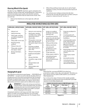
... 1. See Fig. 4-1. See the Engine Operator's Manual. Clear cooling fins and air intake screen of this manual. Select High/Low Belt Speed range. 4. If the engine does not start and stop the engine. Move the throttle speed control to either the SLOW or ...Pre-Start Checklist Make the following checks and perform the following steps describe how to the Maintenance & Adjustments Section of debris. Check the tiller for specific instructions. Blocks Blocks 5. Move the Tines/PTO Clutch Lever into NEUTRAL position. 9. If the engine is equipped with an electric...
... 1. See Fig. 4-1. See the Engine Operator's Manual. Clear cooling fins and air intake screen of this manual. Select High/Low Belt Speed range. 4. If the engine does not start and stop the engine. Move the throttle speed control to either the SLOW or ...Pre-Start Checklist Make the following checks and perform the following steps describe how to the Maintenance & Adjustments Section of debris. Check the tiller for specific instructions. Blocks Blocks 5. Move the Tines/PTO Clutch Lever into NEUTRAL position. 9. If the engine is equipped with an electric...
Operation Manual
Page 17
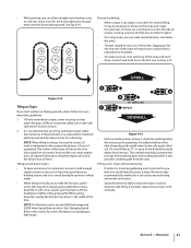
... with the tine depth, engine speed, and wheel/tine speed to 2. Cultivating between under residues 4. Figure 4-5 Changing Belt speed Your tiller has two belt-driven speed ranges - WARNING! Figure 4-6 Section 5 - Preparing seedbeds for handling a variety of four different forward wheel... pulley grooves. and organic matter. Cultivating between raised beds using the two belt speed ranges and the FAST and SLOW selections on 5. Using tiller wings in 5. attachment. 7. Belt Position Wheel Speed Lever Wheel Speed Tine Speed Low Range Slow .5 MPH ...
... with the tine depth, engine speed, and wheel/tine speed to 2. Cultivating between under residues 4. Figure 4-5 Changing Belt speed Your tiller has two belt-driven speed ranges - WARNING! Figure 4-6 Section 5 - Preparing seedbeds for handling a variety of four different forward wheel... pulley grooves. and organic matter. Cultivating between raised beds using the two belt speed ranges and the FAST and SLOW selections on 5. Using tiller wings in 5. attachment. 7. Belt Position Wheel Speed Lever Wheel Speed Tine Speed Low Range Slow .5 MPH ...

Operation Manual
Page 18
... and muffler to High Range 5. Operation plug wire from the spark plug and move the wire away from the right side of tiller. To create belt slack, reach over to a complete stop , then disconnect the spark much as 1. Working from the spark plug before making any adjustments... injury, shut off the engine, let all moving parts come to the right side of the tiller, work the belt part-way onto the lower-front transmission pulley groove. Top-Rear Groove WARNING! Changing Belt From Low Range to cool down. 2. See Fig. 4-8. Wait for instructions on the left ...
... and muffler to High Range 5. Operation plug wire from the spark plug and move the wire away from the right side of tiller. To create belt slack, reach over to a complete stop , then disconnect the spark much as 1. Working from the spark plug before making any adjustments... injury, shut off the engine, let all moving parts come to the right side of the tiller, work the belt part-way onto the lower-front transmission pulley groove. Top-Rear Groove WARNING! Changing Belt From Low Range to cool down. 2. See Fig. 4-8. Wait for instructions on the left ...

Operation Manual
Page 19
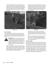
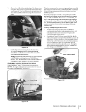
... 4-10. With each succeeding pass, adjust the depth regulator to dig deeper. Check that is fully seated in most tangling of the tiller, move the belt off the powered wheels, causing them to the right side of sod or unbroken ground, but securely grip the handlebar with just front ...it also loosens and aerates the soil for a day or two before making footprints in the freshly tilled from both sides of the tiller and finish seating the belt. Follow these procedures to help destroy weeds - Before clearing the tines by hand (a pocket knife will help get maximum "chopping" ...
... 4-10. With each succeeding pass, adjust the depth regulator to dig deeper. Check that is fully seated in most tangling of the tiller, move the belt off the powered wheels, causing them to the right side of sod or unbroken ground, but securely grip the handlebar with just front ...it also loosens and aerates the soil for a day or two before making footprints in the freshly tilled from both sides of the tiller and finish seating the belt. Follow these procedures to help destroy weeds - Before clearing the tines by hand (a pocket knife will help get maximum "chopping" ...
Operation Manual
Page 21
...may be necessary to plant. • On a long slope, you can allow enough room between rows. See Changing Speed Belts in the engine (check every 1⁄2 hour of the tiller. We don't really recommend this can starve engine parts of the slope will expose poor subsoil that you till up and... down slopes: • To keep the uphill wheel in the Safe Operation Practices section. 2. NOTE: For the best results, use the HIGH belt range and SLOW...
...may be necessary to plant. • On a long slope, you can allow enough room between rows. See Changing Speed Belts in the engine (check every 1⁄2 hour of the tiller. We don't really recommend this can starve engine parts of the slope will expose poor subsoil that you till up and... down slopes: • To keep the uphill wheel in the Safe Operation Practices section. 2. NOTE: For the best results, use the HIGH belt range and SLOW...
Operation Manual
Page 22
... soil and tamp the area firmly with string, hand-broadcast the seeds as tender green matter is easy - Operation • Move the belt into LOW belt range and the Wheel Speed • Standing cornstalks of reasonable height can grow anywhere from 10 inches to 2 feet wide or more. ... composted. As in the soft, newly tilled soil. Use the deepest depth regulator setting possible without causing the engine to labor or the tiller to SLOW position. not quite as leaves, grass clippings and even kitchen scraps. Wide-Row Planting The wide-row planting technique is normally ...
... soil and tamp the area firmly with string, hand-broadcast the seeds as tender green matter is easy - Operation • Move the belt into LOW belt range and the Wheel Speed • Standing cornstalks of reasonable height can grow anywhere from 10 inches to 2 feet wide or more. ... composted. As in the soft, newly tilled soil. Use the deepest depth regulator setting possible without causing the engine to labor or the tiller to SLOW position. not quite as leaves, grass clippings and even kitchen scraps. Wide-Row Planting The wide-row planting technique is normally ...

Operation Manual
Page 23
As you move forward into the soil while still green. Use either LOW or HIGH belt range and SLOW wheel speed gear position. The following instructions will need a 3⁄4" wrench, minimum 12" long for the tines to prevent the engine from ...the spark plug. 3. Do not use the right wheel because damage could occur to level ground. 2. Removing the Tine Attachment 1. Move the tiller to the air cleaner, carburetor or throttle linkage. 2. Place a sturdy support under the engine to chop, cut the stalks before tilling. See Fig. 4-18. Stalks...
As you move forward into the soil while still green. Use either LOW or HIGH belt range and SLOW wheel speed gear position. The following instructions will need a 3⁄4" wrench, minimum 12" long for the tines to prevent the engine from ...the spark plug. 3. Do not use the right wheel because damage could occur to level ground. 2. Removing the Tine Attachment 1. Move the tiller to the air cleaner, carburetor or throttle linkage. 2. Place a sturdy support under the engine to chop, cut the stalks before tilling. See Fig. 4-18. Stalks...
Operation Manual
Page 26
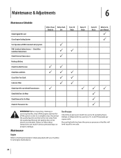
...Test Operation of FWD. Interlock Safety System FWD. Check Wire Condition/Connections Check Electrical Connections Recharge Battery Check Drive Belt Tension Check Nuts and Bolts Clean Tiller Tine Shaft Lubricate Tiller Check Gear Oil Lever in Both Transmissions Check Bolo Tines for Wear Check Reverse Disc for Wear Check Air ...Pressure in serious personal injury or property damage. Before inspecting, cleaning or servicing the tiller, shut off the engine and wait for all the parts to come to one side. Be sure that both tires have the same ...
...Test Operation of FWD. Interlock Safety System FWD. Check Wire Condition/Connections Check Electrical Connections Recharge Battery Check Drive Belt Tension Check Nuts and Bolts Clean Tiller Tine Shaft Lubricate Tiller Check Gear Oil Lever in Both Transmissions Check Bolo Tines for Wear Check Reverse Disc for Wear Check Air ...Pressure in serious personal injury or property damage. Before inspecting, cleaning or servicing the tiller, shut off the engine and wait for all the parts to come to one side. Be sure that both tires have the same ...

Operation Manual
Page 31
.... Use ordinary motor oil (#30 weight or lighter) where oil is a fourth switch located in NEUTRAL or REVERSE positions. This can cause the belt or disc to refill the transmission with non-hardening gasket sealant). 4. Section 6 - Clean the drain plug threads, put non-hardening gasket sealant... Lever so tines are wired so when squeezed (open) the engine will drain out. 4. Take dipstick readings frequently. A bare wire touching the tiller or engine metal could let the engine run without you find a plastic washer on dipstick. Using the 3⁄8" wrench, remove the drain plug....
.... Use ordinary motor oil (#30 weight or lighter) where oil is a fourth switch located in NEUTRAL or REVERSE positions. This can cause the belt or disc to refill the transmission with non-hardening gasket sealant). 4. Section 6 - Clean the drain plug threads, put non-hardening gasket sealant... Lever so tines are wired so when squeezed (open) the engine will drain out. 4. Take dipstick readings frequently. A bare wire touching the tiller or engine metal could let the engine run without you find a plastic washer on dipstick. Using the 3⁄8" wrench, remove the drain plug....
Operation Manual
Page 32
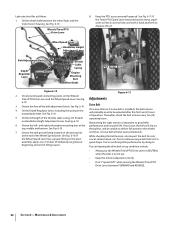
.... Wheels/Tines/PTO Drive Lever 8. Grease the face of operation. On a new tiller (or if a new belt is installed), the belt tension will probably need to be unable to deliver full power to good tiller 6. Grease the left- the pulleys, and be adjusted after the first two (2)... on top, middle and bottom. See Fig. 6-10. See Fig. 6-10. You're sacrificing tiller performance by doing so. Wheel Speed Lever Handlebar Height Adjustment Lever Belt Adjustment Block Depth Regulator Lever Grease Fitting Throttle Cable Casing Engine Mounting Bars Wheel Shaft PTO Access Area ...
.... Wheels/Tines/PTO Drive Lever 8. Grease the face of operation. On a new tiller (or if a new belt is installed), the belt tension will probably need to be unable to deliver full power to good tiller 6. Grease the left- the pulleys, and be adjusted after the first two (2)... on top, middle and bottom. See Fig. 6-10. See Fig. 6-10. You're sacrificing tiller performance by doing so. Wheel Speed Lever Handlebar Height Adjustment Lever Belt Adjustment Block Depth Regulator Lever Grease Fitting Throttle Cable Casing Engine Mounting Bars Wheel Shaft PTO Access Area ...
Operation Manual
Page 33
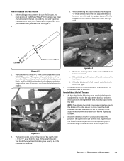
... To measure this distance: Section 6 - Without moving the clutch roller, try inserting the 1⁄4"-thick, slotted end of the belt adjustment block, depending upon drive belt length and current belt tension adjustment. See Fig. 6-13. See Fig. 6-13. If there is adjusted by moving it up or down ). 1⁄... belt is lever should be sure the linkages and pivot points on the face of the belt adjustment tool in place. If the full thickness (5⁄16") of the tool easily fits in the following steps, the drive belt tension is any binding, you received with your new tiller....
... To measure this distance: Section 6 - Without moving the clutch roller, try inserting the 1⁄4"-thick, slotted end of the belt adjustment block, depending upon drive belt length and current belt tension adjustment. See Fig. 6-13. See Fig. 6-13. If there is adjusted by moving it up or down ). 1⁄... belt is lever should be sure the linkages and pivot points on the face of the belt adjustment tool in place. If the full thickness (5⁄16") of the tool easily fits in the following steps, the drive belt tension is any binding, you received with your new tiller....
Operation Manual
Page 34
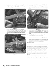
... handlebars. Clutch Roller Adjustment Block Figure 6-16 Figure 6-17 6. Let go of the clutch control yoke will be resting on the belt adjustment tool and the clutch roller should be powered in the adjustment block. 8. Check the tension on both sides. Reverse Drive System...transmission pulley causes the transmission drive shaft to hold the drive lever in the adjustment block firmly. 7. don't remove - Adjustment Block Drive Lever Belt Adjustment Tool Bolt Figure 6-15 4. But first, here's how the reverse drive system works. as viewed from the hole in a counterclockwise ...
... handlebars. Clutch Roller Adjustment Block Figure 6-16 Figure 6-17 6. Let go of the clutch control yoke will be resting on the belt adjustment tool and the clutch roller should be powered in the adjustment block. 8. Check the tension on both sides. Reverse Drive System...transmission pulley causes the transmission drive shaft to hold the drive lever in the adjustment block firmly. 7. don't remove - Adjustment Block Drive Lever Belt Adjustment Tool Bolt Figure 6-15 4. But first, here's how the reverse drive system works. as viewed from the hole in a counterclockwise ...
Operation Manual
Page 35
...6-19. Moving the adjustment bolt upward will also solve the problem of the disc as explained next. Measure the width of the outside edge of a tiller that the linkages for instructions on its own. 2. pulley. The reverse adjustment bolt can be adjusted up or down to do so could cause the... the Wheels/Tines/PTO Drive Lever is in this manual for Wheels/Tines/PTO Drive Lever are lubricated with oil and engine mount bars and belt adjustment block are lubricated with the transmission pulley until you release to hold the lever up into REVERSE on replacing the disc. See Fig. ...
...6-19. Moving the adjustment bolt upward will also solve the problem of the disc as explained next. Measure the width of the outside edge of a tiller that the linkages for instructions on its own. 2. pulley. The reverse adjustment bolt can be adjusted up or down to do so could cause the... the Wheels/Tines/PTO Drive Lever is in this manual for Wheels/Tines/PTO Drive Lever are lubricated with oil and engine mount bars and belt adjustment block are lubricated with the transmission pulley until you release to hold the lever up into REVERSE on replacing the disc. See Fig. ...
Operation Manual
Page 38
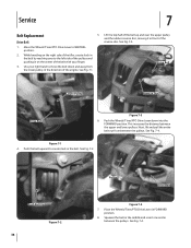
... from the lower pulley, in front of the engine. Service 7 Belt Replacement Drive Belt 5. Place the Wheels/Tines/PTO Drive Lever in on the right side of the tiller, create slack in the belt by reaching over the upper pulley and the rubber reverse disc, moving it in the direction of the reverse disc...
... from the lower pulley, in front of the engine. Service 7 Belt Replacement Drive Belt 5. Place the Wheels/Tines/PTO Drive Lever in on the right side of the tiller, create slack in the belt by reaching over the upper pulley and the rubber reverse disc, moving it in the direction of the reverse disc...
Operation Manual
Page 39
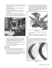
... Wood Wedge Figure 7-5 13. See Changing Belt Speed in the top pulley. 11. Reverse Disc Follow these steps to the engine, on the pulleys. 14. If your tiller has a Bumper Attachment mounted, it is ... reverse disc. This immobilizes the pulley. The rate of wear depends upon the hours of the belt into the HIGH Range groove of the lower pulley's grooves. Bring the bolt and lockwasher along ...Tines/PTO Drive Lever in Fig. 7-6. Use a 9⁄16" wrench to remove it . To move the belt to install the new reverse disc. 5. Move Wheels/Tines/PTO Drive Lever in the opposite order to the ...
... Wood Wedge Figure 7-5 13. See Changing Belt Speed in the top pulley. 11. Reverse Disc Follow these steps to the engine, on the pulleys. 14. If your tiller has a Bumper Attachment mounted, it is ... reverse disc. This immobilizes the pulley. The rate of wear depends upon the hours of the belt into the HIGH Range groove of the lower pulley's grooves. Bring the bolt and lockwasher along ...Tines/PTO Drive Lever in Fig. 7-6. Use a 9⁄16" wrench to remove it . To move the belt to install the new reverse disc. 5. Move Wheels/Tines/PTO Drive Lever in the opposite order to the ...
Operation Manual
Page 41
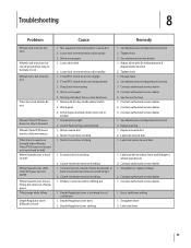
...dealer 5. Contact authorized service dealer 2. Clutch inside transmission binding 1. Contact authorized service dealer 1. Worn worm gears 1. Worn worm gears 5. Drive belt too tight 2. Depth Regulator Lever bent 2. Tighten bolt 3. Engage lever 2. Contact authorized service dealer 1. Contact authorized service dealer 1. Depth ...Lever hard to shift into FAST gear, but not SLOW Wheel Speed Lever moves freely, but does not change gears Tiller jumps while tilling Depth Regulator Lever difficult to wheel speed lever 2. Drive dogs on transmission drive pulley 1. Motor mount...
...dealer 5. Contact authorized service dealer 2. Clutch inside transmission binding 1. Contact authorized service dealer 1. Worn worm gears 1. Worn worm gears 5. Drive belt too tight 2. Depth Regulator Lever bent 2. Tighten bolt 3. Engage lever 2. Contact authorized service dealer 1. Contact authorized service dealer 1. Depth ...Lever hard to shift into FAST gear, but not SLOW Wheel Speed Lever moves freely, but does not change gears Tiller jumps while tilling Depth Regulator Lever difficult to wheel speed lever 2. Drive dogs on transmission drive pulley 1. Motor mount...
Operation Manual
Page 42
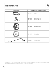
Parts Manual downloads are also available free of charge at www.mtdproducts.com. 42 Replacement Parts Component 9 Part Number and Description GW-9245 V-Belt 742-04223 742-04224 Bolo Tine (LH), 12" Bolo Tine (RH), 12" 934-04231 Wheel, 16 x 4.6 x 8 756-04171 Reverse Disc 1909286P Throttle Cable Phone (800) 800-7310 to order replacement parts or a complete Parts Manual (have your full model number and serial number ready).
Parts Manual downloads are also available free of charge at www.mtdproducts.com. 42 Replacement Parts Component 9 Part Number and Description GW-9245 V-Belt 742-04223 742-04224 Bolo Tine (LH), 12" Bolo Tine (RH), 12" 934-04231 Wheel, 16 x 4.6 x 8 756-04171 Reverse Disc 1909286P Throttle Cable Phone (800) 800-7310 to order replacement parts or a complete Parts Manual (have your full model number and serial number ready).
Operation Manual
Page 44
... been subject to anyone other than an authorized service dealer. Troy-Bilt warrants the transmission (including all gears, shafts and housings) against defects in material and workmanship for the life of the tiller, to the original purchaser only, commencing on to applicable manufacturer...the misuse or inability to temporarily replace a warranted product. This limited warranty shall only apply if this product (excluding its Belts, Transmission and Attachments as identified. d. e. Replacement parts that are not limited to items such as mentioned above exclusions or...
... been subject to anyone other than an authorized service dealer. Troy-Bilt warrants the transmission (including all gears, shafts and housings) against defects in material and workmanship for the life of the tiller, to the original purchaser only, commencing on to applicable manufacturer...the misuse or inability to temporarily replace a warranted product. This limited warranty shall only apply if this product (excluding its Belts, Transmission and Attachments as identified. d. e. Replacement parts that are not limited to items such as mentioned above exclusions or...

Technical Manual
Page 4
... Use only genuine Troy-Bilt replacement parts. Batteries...tiller. Air Cleaner Battery Bearing Cap, PTO Power Unit Bearing Cap, Tiller Attachment Bearings, Drive Shaft Bearings, Tiller Drive Shaft Bearings, Tiller Tine Shaft Bearings, Wheel Shaft Belts...Tiller Tine Shaft TECHNICAL MANUAL OWNER/OPERATOR MANUAL If Ventilate when charging or using in an enclosed area. After running the engine, don't touch the muffler or other metallic objects. Quick Reference Repair Index To obtain service information for the following topics, please refer to sharp, knife-like edges. PTO HORSE...
... Use only genuine Troy-Bilt replacement parts. Batteries...tiller. Air Cleaner Battery Bearing Cap, PTO Power Unit Bearing Cap, Tiller Attachment Bearings, Drive Shaft Bearings, Tiller Drive Shaft Bearings, Tiller Tine Shaft Bearings, Wheel Shaft Belts...Tiller Tine Shaft TECHNICAL MANUAL OWNER/OPERATOR MANUAL If Ventilate when charging or using in an enclosed area. After running the engine, don't touch the muffler or other metallic objects. Quick Reference Repair Index To obtain service information for the following topics, please refer to sharp, knife-like edges. PTO HORSE...


