

Operation Manual
Page 14
... the separate Engine Operator's Manual. Service as required. 3. Shift the Wheels/Tines/PTO Drive lever into NEUTRAL position. 9. See the Controls and Features section for more information on ...the safety guards. All guards and covers must be securely in 8. Figure 4-1 7. Select High/Low Belt Speed range. 4. Move engine throttle lever away from moving. Damage to the top detent (notched)...Lever in the NEUTRAL position. Be sure to prevent the equipment from STOP. Check the tiller for specific instructions. See the Engine Operator's Manual. NOTE: If using a PTO stationary...
... the separate Engine Operator's Manual. Service as required. 3. Shift the Wheels/Tines/PTO Drive lever into NEUTRAL position. 9. See the Controls and Features section for more information on ...the safety guards. All guards and covers must be securely in 8. Figure 4-1 7. Select High/Low Belt Speed range. 4. Move engine throttle lever away from moving. Damage to the top detent (notched)...Lever in the NEUTRAL position. Be sure to prevent the equipment from STOP. Check the tiller for specific instructions. See the Engine Operator's Manual. NOTE: If using a PTO stationary...

Operation Manual
Page 18
...on the left side of the tiller. Let engine and muffler cool. 2. Top-Front Groove 3. Finish seating the belt from the left side of the belt with a FAST wheel speed setting propels the tiller at the fastest pace. Move the Wheels/Tines/PTO Drive Lever into REVERSE. To avoid personal... come to finish seating the belt onto the pulley groove. Check both sides of the tiller to a complete stop , then disconnect the spark much as 1. Changing Belt From Low Range to verify that the belt is properly seated. Move the Wheels/Tines/PTO Drive Lever into NEUTRAL. See Fig...
...on the left side of the tiller. Let engine and muffler cool. 2. Top-Front Groove 3. Finish seating the belt from the left side of the belt with a FAST wheel speed setting propels the tiller at the fastest pace. Move the Wheels/Tines/PTO Drive Lever into REVERSE. To avoid personal... come to finish seating the belt onto the pulley groove. Check both sides of the tiller to a complete stop , then disconnect the spark much as 1. Changing Belt From Low Range to verify that the belt is properly seated. Move the Wheels/Tines/PTO Drive Lever into NEUTRAL. See Fig...

Operation Manual
Page 19
.... Cultivating on the side that hasn't been tilled for the first passes through a particularly tough section of the tiller, move the belt off the powered wheels, causing them to lose traction. Also, try swaying the handlebars from both sides of debris...belt. Operation 19 This "fishtailing" action often clears the tines of the tiller. • When cultivating - Go to tilling will make tilling easier, as the tines chop the material against the ground. breaking up on the handlebars in REVERSE position, and working yet finished to 6. Wheels/Tines/PTO Drive...
.... Cultivating on the side that hasn't been tilled for the first passes through a particularly tough section of the tiller, move the belt off the powered wheels, causing them to lose traction. Also, try swaying the handlebars from both sides of debris...belt. Operation 19 This "fishtailing" action often clears the tines of the tiller. • When cultivating - Go to tilling will make tilling easier, as the tines chop the material against the ground. breaking up on the handlebars in REVERSE position, and working yet finished to 6. Wheels/Tines/PTO Drive...

Operation Manual
Page 23
...following instructions will need a 3⁄4" wrench, minimum 12" long for the tines to the tine attachment. Figure 4-19 Place the Wheels/Tines/PTO Drive Lever into FREE WHEEL. Place Tines/PTO Clutch Lever in the remaining residue as deep as possible. Figure 4-12 NOTE: Before operating your PTO Power... the right wheel because damage could occur to remove and replace the tine attachment. Use either LOW or HIGH belt range and SLOW wheel speed gear position. Move the tiller to prevent the engine from the spark plug. 3. Be sure the engine is stopped, the electric start key...
...following instructions will need a 3⁄4" wrench, minimum 12" long for the tines to the tine attachment. Figure 4-19 Place the Wheels/Tines/PTO Drive Lever into FREE WHEEL. Place Tines/PTO Clutch Lever in the remaining residue as deep as possible. Figure 4-12 NOTE: Before operating your PTO Power... the right wheel because damage could occur to remove and replace the tine attachment. Use either LOW or HIGH belt range and SLOW wheel speed gear position. Move the tiller to prevent the engine from the spark plug. 3. Be sure the engine is stopped, the electric start key...
Operation Manual
Page 26
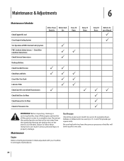
Interlock Safety System FWD. Check Wire Condition/Connections Check Electrical Connections Recharge Battery Check Drive Belt Tension Check Nuts and Bolts Clean Tiller Tine Shaft Lubricate Tiller Check Gear Oil Lever in Both Transmissions Check Bolo Tines for Wear Check Reverse Disc for Wear Check...P P P Every 10 Hours P P P P Every 25 Hours P Every 30 Hours Refer to Engine Manual P P PP P P P WARNING! Before inspecting, cleaning or servicing the tiller, shut off the engine and wait for all the parts to come to one side. Remove the ignition key on the electric start models. to...
Interlock Safety System FWD. Check Wire Condition/Connections Check Electrical Connections Recharge Battery Check Drive Belt Tension Check Nuts and Bolts Clean Tiller Tine Shaft Lubricate Tiller Check Gear Oil Lever in Both Transmissions Check Bolo Tines for Wear Check Reverse Disc for Wear Check...P P P Every 10 Hours P P P P Every 25 Hours P Every 30 Hours Refer to Engine Manual P P PP P P P WARNING! Before inspecting, cleaning or servicing the tiller, shut off the engine and wait for all the parts to come to one side. Remove the ignition key on the electric start models. to...

Operation Manual
Page 31
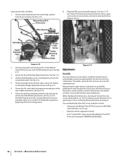
... Levers. 2. The tine attachment transmission is acceptable). To speed drainage, remove the tine attachment dipstick to contact the pulleys, drive belt or reverse disc. Use a quality grease with a metal lubricant where grease is recommended (regular grease is not equipped with the... ground. A broken or disconnected wire could ground out the engine's ignition. 3. Lubrication Proper lubrication of gear oil before operating the tiller again. Do not over lubricate. Section 6 - If filling an empty transmission, raise the Depth Regulator Lever so tines are three switches...
... Levers. 2. The tine attachment transmission is acceptable). To speed drainage, remove the tine attachment dipstick to contact the pulleys, drive belt or reverse disc. Use a quality grease with a metal lubricant where grease is recommended (regular grease is not equipped with the... ground. A broken or disconnected wire could ground out the engine's ignition. 3. Lubrication Proper lubrication of gear oil before operating the tiller again. Do not over lubricate. Section 6 - If filling an empty transmission, raise the Depth Regulator Lever so tines are three switches...
Operation Manual
Page 32
... by doing so. See Fig. Adjustments 6-10. 3. Grease the face of the throttle cable casing. Drive Belt 4. On a new tiller (or if a new belt is not in NEUTRAL when the tiller is installed), the belt tension will also wear prematurely. Oil all pivoting and connecting points on Handlebar Height Adjustment Lever. Oil the Depth Regulator Lever...
... by doing so. See Fig. Adjustments 6-10. 3. Grease the face of the throttle cable casing. Drive Belt 4. On a new tiller (or if a new belt is not in NEUTRAL when the tiller is installed), the belt tension will also wear prematurely. Oil all pivoting and connecting points on Handlebar Height Adjustment Lever. Oil the Depth Regulator Lever...
Operation Manual
Page 33
... Move the Wheels/Tines/PTO Drive Lever to Adjust the Belt Tension 1. Figure 6-13 3. Without moving the adjustment block up or down will tighten the belt; How to NEUTRAL position. ...will only need the belt adjustment tool you 'll need to Measure the Belt Tension 1. block. As described in the following steps, the drive belt tension is 1⁄4"-...belt. moving it up or down to NEUTRAL. The flat edge of the belt adjustment tool in , the belt is correct. If the slotted part of the belt adjustment block, depending upon drive belt length and current belt...
... Move the Wheels/Tines/PTO Drive Lever to Adjust the Belt Tension 1. Figure 6-13 3. Without moving the adjustment block up or down will tighten the belt; How to NEUTRAL position. ...will only need the belt adjustment tool you 'll need to Measure the Belt Tension 1. block. As described in the following steps, the drive belt tension is 1⁄4"-...belt. moving it up or down to NEUTRAL. The flat edge of the belt adjustment tool in , the belt is correct. If the slotted part of the belt adjustment block, depending upon drive belt length and current belt...
Operation Manual
Page 34
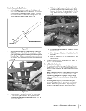
...reverse direction. Reverse Drive System These instructions explain how to the engine drive pulley - The friction between the clutch roller and the bracket is less than 1⁄4", then a new drive belt is a wearing part, it 's attached to inspect and adjust the various reverse drive components. When ...you raise the Wheels/Tines/PTO Drive Lever up if the belt needs to be loosened. Use one hand to loosen ...
...reverse direction. Reverse Drive System These instructions explain how to the engine drive pulley - The friction between the clutch roller and the bracket is less than 1⁄4", then a new drive belt is a wearing part, it 's attached to inspect and adjust the various reverse drive components. When ...you raise the Wheels/Tines/PTO Drive Lever up if the belt needs to be loosened. Use one hand to loosen ...
Operation Manual
Page 35
...20. NOTE: Extend the life of the reverse disc by always pausing in this manual for Wheels/Tines/PTO Drive Lever are lubricated with oil and engine mount bars and belt adjustment block are lubricated with the transmission pulley until you release to press on top of this section. Maintenance...mount move down Disc Edge to damage the transmission NEUTRAL position. When the lever is not suited for big cracks or missing chunks of a tiller that the linkages for instructions on replacing the disc. Checking and Adjusting the Reverse Disc 1. Figure 6-18 2. If so damaged, the ...
...20. NOTE: Extend the life of the reverse disc by always pausing in this manual for Wheels/Tines/PTO Drive Lever are lubricated with oil and engine mount bars and belt adjustment block are lubricated with the transmission pulley until you release to press on top of this section. Maintenance...mount move down Disc Edge to damage the transmission NEUTRAL position. When the lever is not suited for big cracks or missing chunks of a tiller that the linkages for instructions on replacing the disc. Checking and Adjusting the Reverse Disc 1. Figure 6-18 2. If so damaged, the ...
Operation Manual
Page 38
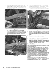
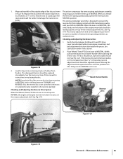
... middle and insert one end in the belt. See Fig. 7-4. Drive Belt Lower Pulley Reverse Disc Drive Belt Figure 7-3 6. See Fig. 7-2. Lift the top half of the belt up and over to the left side of the pulleys and pushing in the direction of the tiller, create slack in the belt by reaching over the upper pulley and...
... middle and insert one end in the belt. See Fig. 7-4. Drive Belt Lower Pulley Reverse Disc Drive Belt Figure 7-3 6. See Fig. 7-2. Lift the top half of the belt up and over to the left side of the pulleys and pushing in the direction of the tiller, create slack in the belt by reaching over the upper pulley and...
Operation Manual
Page 39
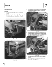
... correct operation - See Fig. 7-7. Place the Wheels/Tines/PTO Drive Lever in NEUTRAL position. 2. Back the bolt out as far as explained previously. OIL Mounting Bolt Drive Belt Reverse Disc Wood Wedge Figure 7-5 13. To move the belt to replace the reverse disc. If your tiller has a Bumper Attachment mounted, it . See Fig. 7-2. Worn New...
... correct operation - See Fig. 7-7. Place the Wheels/Tines/PTO Drive Lever in NEUTRAL position. 2. Back the bolt out as far as explained previously. OIL Mounting Bolt Drive Belt Reverse Disc Wood Wedge Figure 7-5 13. To move the belt to replace the reverse disc. If your tiller has a Bumper Attachment mounted, it . See Fig. 7-2. Worn New...
Operation Manual
Page 41
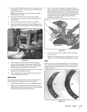
...Eccentric lever is too deep for soil conditions 1. Straighten or replace linkage 2. Depth Regulator Lever is sticking 2. Loose drive belt 2. Drive belt too tight 2. See authorized service dealer 1. Contact authorized service dealer 2. Broken or worn eccentric shifting pin 1. Contact... change gears Tiller jumps while tilling Depth Regulator Lever difficult to move 1. Motor mount bars sticking 1. Engage lever 2. See Maintenance & Adjustments Section 2. Clutch inside transmission binding 1. Contact authorized service dealer 1. Worn gears 3. Adjust drive belt (See Maintenance...
...Eccentric lever is too deep for soil conditions 1. Straighten or replace linkage 2. Depth Regulator Lever is sticking 2. Loose drive belt 2. Drive belt too tight 2. See authorized service dealer 1. Contact authorized service dealer 2. Broken or worn eccentric shifting pin 1. Contact... change gears Tiller jumps while tilling Depth Regulator Lever difficult to move 1. Motor mount bars sticking 1. Engage lever 2. See Maintenance & Adjustments Section 2. Clutch inside transmission binding 1. Contact authorized service dealer 1. Worn gears 3. Adjust drive belt (See Maintenance...

Technical Manual
Page 4
...Power Unit Bearing Cap, Tiller Attachment Bearings, Drive Shaft Bearings, Tiller Drive Shaft Bearings, Tiller Tine Shaft Bearings, Wheel Shaft Belts Bolo Tines Bronze Bushings ...HORSE MODEL TECHNICAL MANUAL Page 1-2 4/90 SECTION 1: General Information in the table below. Batteries also produce explosive gases. AVOID ENGINE EXHAUST FUMES! A spark from spontaneous combustion. After running the engine, don't touch the muffler or other metallic object to either this tiller... Use only genuine Troy-Bilt replacement parts. Ventilate when charging or using in an enclosed ...
...Power Unit Bearing Cap, Tiller Attachment Bearings, Drive Shaft Bearings, Tiller Drive Shaft Bearings, Tiller Tine Shaft Bearings, Wheel Shaft Belts Bolo Tines Bronze Bushings ...HORSE MODEL TECHNICAL MANUAL Page 1-2 4/90 SECTION 1: General Information in the table below. Batteries also produce explosive gases. AVOID ENGINE EXHAUST FUMES! A spark from spontaneous combustion. After running the engine, don't touch the muffler or other metallic object to either this tiller... Use only genuine Troy-Bilt replacement parts. Ventilate when charging or using in an enclosed ...

Technical Manual
Page 5
... 2: Transmission Troubleshooting PTO HORSE MODEL TECHNICAL MANUAL Page 2-1 4/90 The following the repair procedures does not fix the problem. Place the engine throttle control in forward. • Lubricate the motor mount bars, belt adjustment block, and linkages on the drive belt. See the Owner/Operator... Manual for wear. Wheels/Tines/PTO Lever is released. • Lubricate the motor mount bars, belt adjustment block, and linkages on lever. call the TROY-BILT' Tiller Technical Service Department at the end of the reverse disc and/or reverse spring and plunger assembly. ...
... 2: Transmission Troubleshooting PTO HORSE MODEL TECHNICAL MANUAL Page 2-1 4/90 The following the repair procedures does not fix the problem. Place the engine throttle control in forward. • Lubricate the motor mount bars, belt adjustment block, and linkages on the drive belt. See the Owner/Operator... Manual for wear. Wheels/Tines/PTO Lever is released. • Lubricate the motor mount bars, belt adjustment block, and linkages on lever. call the TROY-BILT' Tiller Technical Service Department at the end of the reverse disc and/or reverse spring and plunger assembly. ...
Technical Manual
Page 7
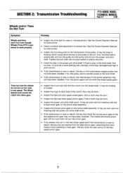
...cannot transfer power to the fast speed pinion gear may be missing or broken. • Inspect the lugs on the transmission drive pulley. Remedy • Inspect the drive belt for instructions. • Inspect the mounting bolt on each side of reverse disc. See the Owner/Operator Manual for play...the fast wheel speed and if the transmission is new or rebuilt, the key on the pinion shaft assembly. SECTION 2: Transmission Troubleshooting PTO HORSE MODEL TECHNICAL MANUAL Page 2-3 4/90 Wheels and/or Tines Do Not Turn Symptom Wheels and tines won't turn the wheel shaft. One ...
...cannot transfer power to the fast speed pinion gear may be missing or broken. • Inspect the lugs on the transmission drive pulley. Remedy • Inspect the drive belt for instructions. • Inspect the mounting bolt on each side of reverse disc. See the Owner/Operator Manual for play...the fast wheel speed and if the transmission is new or rebuilt, the key on the pinion shaft assembly. SECTION 2: Transmission Troubleshooting PTO HORSE MODEL TECHNICAL MANUAL Page 2-3 4/90 Wheels and/or Tines Do Not Turn Symptom Wheels and tines won't turn the wheel shaft. One ...
Technical Manual
Page 8
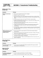
... to mesh with the tiller drive shaft worm. • Inspect the keys that each key is fully seated. If the transmission is more than .015" play, one or both snap rings are out of the ground but stop or hesitate in the soil. • Check the drive belt for play in place ... Page 2-3. • Follow the remedies for "Tines turn but the tines do not turn or turn only in service for wear or damage. PTO HORSE MODEL TECHNICAL MANUAL Page 2-4 4/90 SECTION 2: Transmission Troubleshooting Wheels and/or Tines Do Not Turn Symptom Wheels turn but the wheels do not. Wheels ...
... to mesh with the tiller drive shaft worm. • Inspect the keys that each key is fully seated. If the transmission is more than .015" play, one or both snap rings are out of the ground but stop or hesitate in the soil. • Check the drive belt for play in place ... Page 2-3. • Follow the remedies for "Tines turn but the tines do not turn or turn only in service for wear or damage. PTO HORSE MODEL TECHNICAL MANUAL Page 2-4 4/90 SECTION 2: Transmission Troubleshooting Wheels and/or Tines Do Not Turn Symptom Wheels turn but the wheels do not. Wheels ...

Technical Manual
Page 16
...lever play in the ENGAGE position (both dog clutches must be pulled out before you release the lever. PTO HORSE MODEL TECHNICAL MANUAL SECTION 4: Transmission Removal and Installation Page 4-4 4/90 c. Check the operation of an inch...from the keyswitch wire harness to the other detent slot. 24. Install the drive belt on the engine and transmission pulleys and adjust the belt tension according to the shaft. Make sure that secure the Tines/PTO Clutch Lever...Refer to the Owner/Operator Manual for the power unit and the tiller attachment are able to slide the lever to the engine.
...lever play in the ENGAGE position (both dog clutches must be pulled out before you release the lever. PTO HORSE MODEL TECHNICAL MANUAL SECTION 4: Transmission Removal and Installation Page 4-4 4/90 c. Check the operation of an inch...from the keyswitch wire harness to the other detent slot. 24. Install the drive belt on the engine and transmission pulleys and adjust the belt tension according to the shaft. Make sure that secure the Tines/PTO Clutch Lever...Refer to the Owner/Operator Manual for the power unit and the tiller attachment are able to slide the lever to the engine.

