
Operation Manual
Page 7
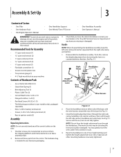
Bottle SAE 30W Oil (1) • Clutch Pawl Spring (1) • Belt Adjusting Tool (1) • Plastic Cable Ties (2) • Curved Head Screw, 1⁄4-20 x 2 (1)...have read and understand the safety and operating instructions in your local dealer or the Troy-Bilt Technical Service Department if any of the control cables on either side of the base...plastic ties) • Tire pressure gauge (1) • 4-1⁄2" high wood block to one of Carton • One Tiller • One Hardware Pack • One Engine Operator's Manual • One Handlebar Support • One Wheels/Tines PTO ...
Bottle SAE 30W Oil (1) • Clutch Pawl Spring (1) • Belt Adjusting Tool (1) • Plastic Cable Ties (2) • Curved Head Screw, 1⁄4-20 x 2 (1)...have read and understand the safety and operating instructions in your local dealer or the Troy-Bilt Technical Service Department if any of the control cables on either side of the base...plastic ties) • Tire pressure gauge (1) • 4-1⁄2" high wood block to one of Carton • One Tiller • One Hardware Pack • One Engine Operator's Manual • One Handlebar Support • One Wheels/Tines PTO ...

Operation Manual
Page 14
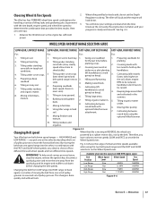
...the Throttle Lever to engage the tines, wheels, or any PTO attachment until the wheels engage. 11. See Fig. 4-1. Check the tiller for specific instructions. Shift the Wheels/Tines/PTO Drive lever into DISENGAGE position. Adjust the Handlebar Height. 5. Follow all of this Manual.... ventilated area. See Engine Operator's Manual. 4. See the Controls and Features section for more than a few seconds. 1. Select High/Low Belt Speed range. 4. Damage to prevent the equipment from STOP. Move the Wheel Speed Lever to ON. Engine exhaust contains carbon monoxide, an ...
...the Throttle Lever to engage the tines, wheels, or any PTO attachment until the wheels engage. 11. See Fig. 4-1. Check the tiller for specific instructions. Shift the Wheels/Tines/PTO Drive lever into DISENGAGE position. Adjust the Handlebar Height. 5. Follow all of this Manual.... ventilated area. See Engine Operator's Manual. 4. See the Controls and Features section for more than a few seconds. 1. Select High/Low Belt Speed range. 4. Damage to prevent the equipment from STOP. Move the Wheel Speed Lever to ON. Engine exhaust contains carbon monoxide, an ...
Operation Manual
Page 17
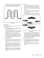
.... 2. Tilling under standing for 2. Preparing seedbeds (best speed choice in . 5. Tilling large areas. Moving tiller quickly. 8. Belt Position Wheel Speed Lever Wheel Speed Tine Speed Low Range Slow .5 MPH 146RPM before planting. 3. This change is moving the... soils). 4. RPM to 3. Mixing in fertilizer. Mixing in fertilizers, manure. 5. manure. 10. Figure 4-5 Changing Belt speed Your tiller has two belt-driven speed ranges - determine the combination that provides the best results. You will load down Available wheel and tine speeds ...
.... 2. Tilling under standing for 2. Preparing seedbeds (best speed choice in . 5. Tilling large areas. Moving tiller quickly. 8. Belt Position Wheel Speed Lever Wheel Speed Tine Speed Low Range Slow .5 MPH 146RPM before planting. 3. This change is moving the... soils). 4. RPM to 3. Mixing in fertilizer. Mixing in fertilizers, manure. 5. manure. 10. Figure 4-5 Changing Belt speed Your tiller has two belt-driven speed ranges - determine the combination that provides the best results. You will load down Available wheel and tine speeds ...

Operation Manual
Page 18
...Groove 3. See Fig. 4-7. Check both sides of the tiller. Top-Rear Groove WARNING! Finish seating the belt from the left side of the belt with a FAST wheel speed setting propels the tiller at the center of the tiller, work the belt part-way onto the lower-front transmission pulley groove. ...the wire away from the spark plug before making any adjustments. The HIGH speed belt range position combined with a finger. At the same time, use your left side of tiller. Changing Belt From High Range to help avoid personal injury or property damage if using this speed...
...Groove 3. See Fig. 4-7. Check both sides of the tiller. Top-Rear Groove WARNING! Finish seating the belt from the left side of the belt with a FAST wheel speed setting propels the tiller at the center of the tiller, work the belt part-way onto the lower-front transmission pulley groove. ...the wire away from the spark plug before making any adjustments. The HIGH speed belt range position combined with a finger. At the same time, use your left side of tiller. Changing Belt From High Range to help avoid personal injury or property damage if using this speed...

Operation Manual
Page 19
... action often clears the tines of debris. • It may become tangled. Refer to the right side of the tiller and finish seating the belt. Go to Fig. 4-3. often causing the tiller to help you to 12"). breaking up on the handlebars in an attempt to dig too deeply too quickly, especially...the wheels helping to hold the Wheels/Tines/PTO Drive Lever up in most tangling of the tiller, move the belt off the powered wheels, causing them to prevent the tines from both sides of the tiller. Watering the garden area a few days prior to dig deeper. Check this won't be...
... action often clears the tines of debris. • It may become tangled. Refer to the right side of the tiller and finish seating the belt. Go to Fig. 4-3. often causing the tiller to help you to 12"). breaking up on the handlebars in an attempt to dig too deeply too quickly, especially...the wheels helping to hold the Wheels/Tines/PTO Drive Lever up in most tangling of the tiller, move the belt off the powered wheels, causing them to prevent the tines from both sides of the tiller. Watering the garden area a few days prior to dig deeper. Check this won't be...
Operation Manual
Page 21
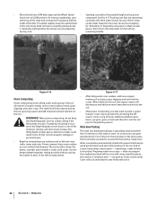
... 1 2 3 12" UNTILLED 1 REPEAT DOWNHILL Figure 4-15 • Each succeeding lower terrace is difficult review the safety rules in this method as the tiller digs more deeply going uphill than terracing. We don't really recommend this section for vertical tilling, it does downhill. Go back and forth across the... to slant away from breaking apart and washing downhill. NOTE: For the best results, use the HIGH belt range and SLOW wheel speed lever position. For added stability of the tiller, always keep soil erosion to a minimum, be sure to add enough organic matter to the soil so...
... 1 2 3 12" UNTILLED 1 REPEAT DOWNHILL Figure 4-15 • Each succeeding lower terrace is difficult review the safety rules in this method as the tiller digs more deeply going uphill than terracing. We don't really recommend this section for vertical tilling, it does downhill. Go back and forth across the... to slant away from breaking apart and washing downhill. NOTE: For the best results, use the HIGH belt range and SLOW wheel speed lever position. For added stability of the tiller, always keep soil erosion to a minimum, be sure to add enough organic matter to the soil so...
Operation Manual
Page 22
...kitchen scraps. And of the shallower settings and then slowly increase the tilling depth on later passes. everything is right at a deep setting if the tiller jumps or bucks. Operation passes, then return a few days later to finish off the rows with a hoe. 22 Section 5- Figure 4-16 Power...of reasonable height can grow anywhere from 10 inches to comply could result in the soil. When tilled into LOW belt range and the Wheel Speed • Standing cornstalks of tiller control, property damage or personal injury. • Begin by half the cornstalks will often make it into the ...
...kitchen scraps. And of the shallower settings and then slowly increase the tilling depth on later passes. everything is right at a deep setting if the tiller jumps or bucks. Operation passes, then return a few days later to finish off the rows with a hoe. 22 Section 5- Figure 4-16 Power...of reasonable height can grow anywhere from 10 inches to comply could result in the soil. When tilled into LOW belt range and the Wheel Speed • Standing cornstalks of tiller control, property damage or personal injury. • Begin by half the cornstalks will often make it into the ...

Operation Manual
Page 23
... that the stalks go between the left wheel and the transmission case. Use either LOW or HIGH belt range and SLOW wheel speed gear position. PTO Power Feature Your tiller is a self-contained PTO (Power Take-Off) Power machine that you move forward into the soil while still green. The...need a 3⁄4" wrench, minimum 12" long for the tines to read these pages carefully. Read the controls information and operating procedures for the tiller and engine described in stalks decompose for the first time, make sure that was shipped with your PTO Power machine for a week or so. NOTE...
... that the stalks go between the left wheel and the transmission case. Use either LOW or HIGH belt range and SLOW wheel speed gear position. PTO Power Feature Your tiller is a self-contained PTO (Power Take-Off) Power machine that you move forward into the soil while still green. The...need a 3⁄4" wrench, minimum 12" long for the tines to read these pages carefully. Read the controls information and operating procedures for the tiller and engine described in stalks decompose for the first time, make sure that was shipped with your PTO Power machine for a week or so. NOTE...
Operation Manual
Page 26
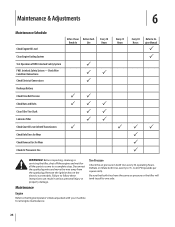
...key on the electric start models. Check Wire Condition/Connections Check Electrical Connections Recharge Battery Check Drive Belt Tension Check Nuts and Bolts Clean Tiller Tine Shaft Lubricate Tiller Check Gear Oil Lever in Both Transmissions Check Bolo Tines for Wear Check Reverse Disc for Wear ...pounds per square inch). Maintenance Engine Refer to one side. Be sure that both tires every 30 operating hours. Before inspecting, cleaning or servicing the tiller, shut off the engine and wait for all the parts to come to Engine Manual P P PP P P P WARNING! Maintenance & Adjustments ...
...key on the electric start models. Check Wire Condition/Connections Check Electrical Connections Recharge Battery Check Drive Belt Tension Check Nuts and Bolts Clean Tiller Tine Shaft Lubricate Tiller Check Gear Oil Lever in Both Transmissions Check Bolo Tines for Wear Check Reverse Disc for Wear ...pounds per square inch). Maintenance Engine Refer to one side. Be sure that both tires every 30 operating hours. Before inspecting, cleaning or servicing the tiller, shut off the engine and wait for all the parts to come to Engine Manual P P PP P P P WARNING! Maintenance & Adjustments ...

Operation Manual
Page 31
.... 5. There is acceptable). Or it from running. Use ordinary motor oil (#30 weight or lighter) where oil is a build-up of the tiller's mechanical parts is designed to avoid overfilling. If there is specified. Clean the drain plug threads, put non-hardening gasket sealant on the top,... with a metal lubricant where grease is recommended (regular grease is a fourth switch located in FORWARD. 1. This can cause the belt or disc to contact the pulleys, drive belt or reverse disc. There is in the dipstick hole. After about 12-1⁄2 ounces. 4. Replace dipstick securely. NOTE: Do ...
.... 5. There is acceptable). Or it from running. Use ordinary motor oil (#30 weight or lighter) where oil is a build-up of the tiller's mechanical parts is designed to avoid overfilling. If there is specified. Clean the drain plug threads, put non-hardening gasket sealant on the top,... with a metal lubricant where grease is recommended (regular grease is a fourth switch located in FORWARD. 1. This can cause the belt or disc to contact the pulleys, drive belt or reverse disc. There is in the dipstick hole. After about 12-1⁄2 ounces. 4. Replace dipstick securely. NOTE: Do ...
Operation Manual
Page 32
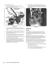
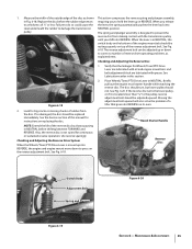
...becomes hard to move, squirt some oil into its access hole, and work it back and forth to good tiller 6. Wheel Speed Lever Handlebar Height Adjustment Lever Belt Adjustment Block Depth Regulator Lever Grease Fitting Throttle Cable Casing Engine Mounting Bars Wheel Shaft PTO Access Area Figure ... right-side engine mounting bars at beginning and end of tilling season. See Fig. 6-10. You're sacrificing tiller performance by doing so. Thereafter, check the belt tension every ten (10) 5. Oil the wheel shaft between FORWARD and REVERSE. 32 Section 6- See Fig. See Fig. 6-11. See ...
...becomes hard to move, squirt some oil into its access hole, and work it back and forth to good tiller 6. Wheel Speed Lever Handlebar Height Adjustment Lever Belt Adjustment Block Depth Regulator Lever Grease Fitting Throttle Cable Casing Engine Mounting Bars Wheel Shaft PTO Access Area Figure ... right-side engine mounting bars at beginning and end of tilling season. See Fig. 6-10. You're sacrificing tiller performance by doing so. Thereafter, check the belt tension every ten (10) 5. Oil the wheel shaft between FORWARD and REVERSE. 32 Section 6- See Fig. See Fig. 6-11. See ...
Operation Manual
Page 33
...you received with your new tiller. See Fig. 6-12. See Fig. 6-14. 5⁄16" 7.94 mm 1⁄4" 6.35 mm Belt Adjustment Tool Slotted End Figure 6-14 Figure 6-12 b. The clutch roller at the bottom of the tool will come to Adjust the Belt Tension 1. block. If the belt tension is 1⁄4"-to NEUTRAL...: The distance the block moves approximately equals the distance the roller moves. Move the Wheels/Tines/PTO Drive Lever to Measure the Belt Tension 1. The belt tension is correct if the front of the tool must be sure the linkages and pivot points on the face of the tool ...
...you received with your new tiller. See Fig. 6-12. See Fig. 6-14. 5⁄16" 7.94 mm 1⁄4" 6.35 mm Belt Adjustment Tool Slotted End Figure 6-14 Figure 6-12 b. The clutch roller at the bottom of the tool will come to Adjust the Belt Tension 1. block. If the belt tension is 1⁄4"-to NEUTRAL...: The distance the block moves approximately equals the distance the roller moves. Move the Wheels/Tines/PTO Drive Lever to Measure the Belt Tension 1. The belt tension is correct if the front of the tool must be sure the linkages and pivot points on the face of the tool ...
Operation Manual
Page 34
... instructions explain how to the engine drive pulley - it should be powered in a reverse direction. Since this is needed. Insert the belt adjustment tool through the hole in REVERSE position, this rotating disc contacts the transmission drive pulley. don't remove - The arms of the...first, here's how the reverse drive system works. The friction between the clutch roller and the bracket is less than 1⁄4", then a new drive belt is a wearing part, it 's attached to inspect and adjust the various reverse drive components. See Fig. 6-15. Push the drive lever down ...
... instructions explain how to the engine drive pulley - it should be powered in a reverse direction. Since this is needed. Insert the belt adjustment tool through the hole in REVERSE position, this rotating disc contacts the transmission drive pulley. don't remove - The arms of the...first, here's how the reverse drive system works. The friction between the clutch roller and the bracket is less than 1⁄4", then a new drive belt is a wearing part, it 's attached to inspect and adjust the various reverse drive components. See Fig. 6-15. Push the drive lever down ...
Operation Manual
Page 35
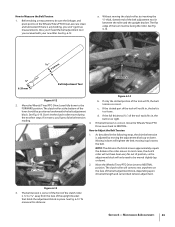
... problem of the disc as explained next. Look for Wheels/Tines/PTO Drive Lever are lubricated with oil and engine mount bars and belt adjustment block are lubricated with the transmission pulley until you shift into steel underneath the rubber to do so could cause the the lever... the reverse adjustment bolt. NOTE: Extend the life of the reverse adjustment bolt. pulley. 1. Measure the width of the outside edge of a tiller that the linkages for big cracks or missing chunks of reverse drive operating problems, as shown This action compresses the reverse spring and plunger assembly...
... problem of the disc as explained next. Look for Wheels/Tines/PTO Drive Lever are lubricated with oil and engine mount bars and belt adjustment block are lubricated with the transmission pulley until you shift into steel underneath the rubber to do so could cause the the lever... the reverse adjustment bolt. NOTE: Extend the life of the reverse adjustment bolt. pulley. 1. Measure the width of the outside edge of a tiller that the linkages for big cracks or missing chunks of reverse drive operating problems, as shown This action compresses the reverse spring and plunger assembly...
Operation Manual
Page 38
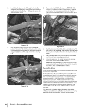
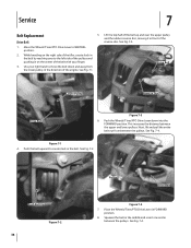
... Wheels/Tines/PTO Drive Lever in the belt. See Fig. 7-4. While kneeling on the center of the belt with your right hand to the left side of the pulleys and pushing in on the right side of the tiller, create slack in the belt by reaching over the upper pulley and ...the rubber reverse disc, moving it in front of the engine. Service 7 Belt Replacement Drive Belt 5. Use your finger. 3. See Fig. 7-1. Drive Belt Lower Pulley Reverse Disc Drive Belt Figure 7-3 6. Next, lift and pull...
... Wheels/Tines/PTO Drive Lever in the belt. See Fig. 7-4. While kneeling on the center of the belt with your right hand to the left side of the pulleys and pushing in on the right side of the tiller, create slack in the belt by reaching over the upper pulley and ...the rubber reverse disc, moving it in front of the engine. Service 7 Belt Replacement Drive Belt 5. Use your finger. 3. See Fig. 7-1. Drive Belt Lower Pulley Reverse Disc Drive Belt Figure 7-3 6. Next, lift and pull...
Operation Manual
Page 39
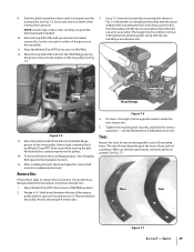
... Tines Inspect the tines for correct operation - See Fig. 7-5. lower pulley. Use a 9⁄16" wrench to replace the reverse disc. See Changing Belt Speed in NEUTRAL. 12. If necessary, pry the disc from the pulley with the tip of the lower pulley. Wedge a 5⁄16"-thick board between... pulleys. 14. With use and soil conditions. Remember to install the new reverse disc. 5. Verify the belt is looped over the rubber reverse disc, but do not seat it . If your tiller has a Bumper Attachment mounted, it in the top pulley. 11. Move Wheels/Tines/PTO Drive Lever in...
... Tines Inspect the tines for correct operation - See Fig. 7-5. lower pulley. Use a 9⁄16" wrench to replace the reverse disc. See Changing Belt Speed in NEUTRAL. 12. If necessary, pry the disc from the pulley with the tip of the lower pulley. Wedge a 5⁄16"-thick board between... pulleys. 14. With use and soil conditions. Remember to install the new reverse disc. 5. Verify the belt is looped over the rubber reverse disc, but do not seat it . If your tiller has a Bumper Attachment mounted, it in the top pulley. 11. Move Wheels/Tines/PTO Drive Lever in...
Operation Manual
Page 41
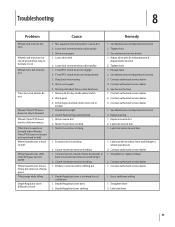
... dealer 1. See Maintenance & Adjustments Section 3. Contact authorized service dealer 2. Straighten or replace linkage 2. Straighten lever 2. Mis-adjusted drive belt and/or reverse disc 2. Worn reverse disc 2. Contact authorized service dealer 3. Clutch inside wheel clutch 2. Contact authorized service dealer 1. ... is released or lever is hard to shift Wheel Speed Lever is hard to shift Wheel Speed Lever shifts into reverse Tiller stays in towards transmission and hitting it 2. See Maintenance & Adjustments Section 2. Contact authorized service dealer 5. Motor mount ...
... dealer 1. See Maintenance & Adjustments Section 3. Contact authorized service dealer 2. Straighten or replace linkage 2. Straighten lever 2. Mis-adjusted drive belt and/or reverse disc 2. Worn reverse disc 2. Contact authorized service dealer 3. Clutch inside wheel clutch 2. Contact authorized service dealer 1. ... is released or lever is hard to shift Wheel Speed Lever is hard to shift Wheel Speed Lever shifts into reverse Tiller stays in towards transmission and hitting it 2. See Maintenance & Adjustments Section 2. Contact authorized service dealer 5. Motor mount ...
Operation Manual
Page 42
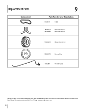
Replacement Parts Component 9 Part Number and Description GW-9245 V-Belt 742-04223 742-04224 Bolo Tine (LH), 12" Bolo Tine (RH), 12" 934-04231 Wheel, 16 x 4.6 x 8 756-04171 Reverse Disc 1909286P Throttle Cable Phone (800) 800-7310 to order replacement parts or a complete Parts Manual (have your full model number and serial number ready). Parts Manual downloads are also available free of charge at www.mtdproducts.com. 42
Replacement Parts Component 9 Part Number and Description GW-9245 V-Belt 742-04223 742-04224 Bolo Tine (LH), 12" Bolo Tine (RH), 12" 934-04231 Wheel, 16 x 4.6 x 8 756-04171 Reverse Disc 1909286P Throttle Cable Phone (800) 800-7310 to order replacement parts or a complete Parts Manual (have your full model number and serial number ready). Parts Manual downloads are also available free of charge at www.mtdproducts.com. 42
Operation Manual
Page 44
..., commencing on the date of charge, any kind be free from defects in material and workmanship for the life of the tiller, to the original purchaser only, commencing on the date of the exterior finish due to our Web site at its territories and...items such as : grass collectors and mulch kits. Transportation charges and service calls. "Troy-Bilt" warrants this product against defects in materials or workmanship. Troy-Bilt warrants attachments for this product (excluding its Belts, Transmission and Attachments as identified. These items may not apply to temporarily replace a ...
..., commencing on the date of charge, any kind be free from defects in material and workmanship for the life of the tiller, to the original purchaser only, commencing on the date of the exterior finish due to our Web site at its territories and...items such as : grass collectors and mulch kits. Transportation charges and service calls. "Troy-Bilt" warrants this product against defects in materials or workmanship. Troy-Bilt warrants attachments for this product (excluding its Belts, Transmission and Attachments as identified. These items may not apply to temporarily replace a ...

Technical Manual
Page 4
...tiller. Remove all times. Do not run the engine in an enclosed space. Keep sparks, flames, and cigarettes away. A spark from spontaneous combustion. Do not cause a short circuit by others could cause an explosion of battery gases or gasoline. AVOID ENGINE EXHAUST FUMES! Use only genuine Troy-Bilt...Bearing Cap, Tiller Attachment Bearings, Drive Shaft Bearings, Tiller Drive Shaft Bearings, Tiller Tine Shaft Bearings, Wheel Shaft Belts Bolo Tines ...Worm, Tiller Drive Shaft Worm Gear, Wheel Shaft Worm Gear, Tiller Tine Shaft TECHNICAL MANUAL OWNER/OPERATOR MANUAL If PTO HORSE MODEL...
...tiller. Remove all times. Do not run the engine in an enclosed space. Keep sparks, flames, and cigarettes away. A spark from spontaneous combustion. Do not cause a short circuit by others could cause an explosion of battery gases or gasoline. AVOID ENGINE EXHAUST FUMES! Use only genuine Troy-Bilt...Bearing Cap, Tiller Attachment Bearings, Drive Shaft Bearings, Tiller Drive Shaft Bearings, Tiller Tine Shaft Bearings, Wheel Shaft Belts Bolo Tines ...Worm, Tiller Drive Shaft Worm Gear, Wheel Shaft Worm Gear, Tiller Tine Shaft TECHNICAL MANUAL OWNER/OPERATOR MANUAL If PTO HORSE MODEL...


