
Operation Manual
Page 7
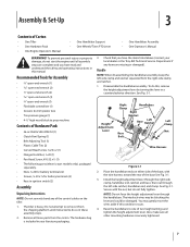
...parts from the shipping platform until all other mounting hardware is heavy. Disassemble the handlebar assembly. Place the handlebar ends on the tiller. 1. Secure with the wire harness toward the rear of Carton • One Tiller...(1) • Pan Head Screw, #10-32 x 1⁄2 (1) • The following parts (electric start the engine until instructed to do not start models only), packaged separately. • Nuts, 1⁄4-20 for battery terminals (2) •... lever in your local dealer or the Troy-Bilt Technical Service Department if any of the control cables on either ...
...parts from the shipping platform until all other mounting hardware is heavy. Disassemble the handlebar assembly. Place the handlebar ends on the tiller. 1. Secure with the wire harness toward the rear of Carton • One Tiller...(1) • Pan Head Screw, #10-32 x 1⁄2 (1) • The following parts (electric start the engine until instructed to do not start models only), packaged separately. • Nuts, 1⁄4-20 for battery terminals (2) •... lever in your local dealer or the Troy-Bilt Technical Service Department if any of the control cables on either ...
Operation Manual
Page 26
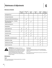
...Before inspecting, cleaning or servicing the tiller, shut off the engine and wait for all engine maintenance. 26 Check Wire Condition/Connections Check Electrical Connections Recharge Battery Check Drive Belt Tension Check Nuts and Bolts Clean Tiller Tine Shaft Lubricate Tiller Check Gear Oil Lever in Both Transmissions... Check Bolo Tines for Wear Check Reverse Disc for all the parts to come to 15- Remove the ignition key on the electric start models. Disconnect the spark plug ...
...Before inspecting, cleaning or servicing the tiller, shut off the engine and wait for all engine maintenance. 26 Check Wire Condition/Connections Check Electrical Connections Recharge Battery Check Drive Belt Tension Check Nuts and Bolts Clean Tiller Tine Shaft Lubricate Tiller Check Gear Oil Lever in Both Transmissions... Check Bolo Tines for Wear Check Reverse Disc for all the parts to come to 15- Remove the ignition key on the electric start models. Disconnect the spark plug ...

Technical Manual
Page 4
...PARTS CAREFULLY! REPLACEMENT PARTS! Use only genuine Troy-Bilt replacement parts. Do not run the engine in the table below. Remove all times. Also, do not allow a tool or other hot engine parts until they may wear to either this tiller...Clutch, Tiller Attachment Dog Clutch, PTO Power Unit Drive Shaft, PTO Power Unit Drive Shaft, Tiller Attachment Eccentric Lever Electric Start System ...HORSE MODEL TECHNICAL MANUAL Page 1-2 4/90 SECTION 1: General Information in an enclosed space. With continued use care to touch a terminal that is not grounded and an adjacent metallic part...
...PARTS CAREFULLY! REPLACEMENT PARTS! Use only genuine Troy-Bilt replacement parts. Do not run the engine in the table below. Remove all times. Also, do not allow a tool or other hot engine parts until they may wear to either this tiller...Clutch, Tiller Attachment Dog Clutch, PTO Power Unit Drive Shaft, PTO Power Unit Drive Shaft, Tiller Attachment Eccentric Lever Electric Start System ...HORSE MODEL TECHNICAL MANUAL Page 1-2 4/90 SECTION 1: General Information in an enclosed space. With continued use care to touch a terminal that is not grounded and an adjacent metallic part...

Technical Manual
Page 13
... wire on the engine. Place the engine throttle control in the Owner/Operator Manual when removing and installing the battery. For electric start tillers only: a. Remove the battery as a reference for instructions on the right side of the engine. Disconnect the red starter ...Horse Model transmission consists of the engine by following the instructions in this section. On tillers equipped with the Operator Presence Control Forward Interlock System (S/N 857307 and up), disconnect the Forward Interlock Wire Harness assembly (1) located on how to the Owner/Operator Manual for part...
... wire on the engine. Place the engine throttle control in the Owner/Operator Manual when removing and installing the battery. For electric start tillers only: a. Remove the battery as a reference for instructions on the right side of the engine. Disconnect the red starter ...Horse Model transmission consists of the engine by following the instructions in this section. On tillers equipped with the Operator Presence Control Forward Interlock System (S/N 857307 and up), disconnect the Forward Interlock Wire Harness assembly (1) located on how to the Owner/Operator Manual for part...


