

Operation Manual
Page 14
... the Engine engine starts. Pre-Start Checklist Make the following checks and perform the following steps describe how to 2. Check the tiller for specific instructions. All guards and covers must be securely in an enclosed, poorly ventilated area. See the Engine Operator's Manual...separate Engine Operator's Manual. to either the SLOW or FAST position. gas. Put the Depth Regulator Lever in the FORWARD position, the starter motor can occur if it is cranked more than a few seconds. 1. Figure 4-1 7. Move engine throttle lever away from moving. Damage to...
... the Engine engine starts. Pre-Start Checklist Make the following checks and perform the following steps describe how to 2. Check the tiller for specific instructions. All guards and covers must be securely in an enclosed, poorly ventilated area. See the Engine Operator's Manual...separate Engine Operator's Manual. to either the SLOW or FAST position. gas. Put the Depth Regulator Lever in the FORWARD position, the starter motor can occur if it is cranked more than a few seconds. 1. Figure 4-1 7. Move engine throttle lever away from moving. Damage to...
Operation Manual
Page 15
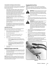
...Depth Regulator Lever to FREEWHEEL (then block the wheels so they can't roll). Refer to the Engine Operator's Manual for the motor oil specifications for more information. Warm the engine up the transmission gear oil as applicable. Test the Forward Interlock Safety System...., melt the ice with forward rotating tines. The Forward Interlock Safety System is in a completely different manner than counter-rotating-tine (CRT) tillers, or from damage: 1. Then on the engine. The engine will prevent electrical discharge. • Before pulling the recoil starter rope, turn...
...Depth Regulator Lever to FREEWHEEL (then block the wheels so they can't roll). Refer to the Engine Operator's Manual for the motor oil specifications for more information. Warm the engine up the transmission gear oil as applicable. Test the Forward Interlock Safety System...., melt the ice with forward rotating tines. The Forward Interlock Safety System is in a completely different manner than counter-rotating-tine (CRT) tillers, or from damage: 1. Then on the engine. The engine will prevent electrical discharge. • Before pulling the recoil starter rope, turn...
Operation Manual
Page 27
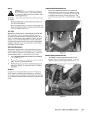
... the left - Jam Nut Figure 6-2 Section 6 - Prop the transmission up . • After cleaning the battery and terminals, apply a light coat of the motor mount casting. Most hardware on your tiller is located on the tine shaft or inside the tine holders. Refer to hardware listed below. Please follow this maintenance recommendation, as...
... the left - Jam Nut Figure 6-2 Section 6 - Prop the transmission up . • After cleaning the battery and terminals, apply a light coat of the motor mount casting. Most hardware on your tiller is located on the tine shaft or inside the tine holders. Refer to hardware listed below. Please follow this maintenance recommendation, as...

Operation Manual
Page 31
... Once all plugs. Lubrication Proper lubrication of the transmission will run . When oil seeps from the Power Unit. 2. b. Remove the dipstick from the tiller housing cover. Stop when oil reaches "Cold" range marking on the threads, and reinstall the plug. 5. A broken or disconnected wire could ground out ... so any oil at a time to press one of gear oil before operating the tiller again. The switches are three switches in the dipstick hole. Use ordinary motor oil (#30 weight or lighter) where oil is designed to engage its threads with an oil drain plug. NOTE:...
... Once all plugs. Lubrication Proper lubrication of the transmission will run . When oil seeps from the Power Unit. 2. b. Remove the dipstick from the tiller housing cover. Stop when oil reaches "Cold" range marking on the threads, and reinstall the plug. 5. A broken or disconnected wire could ground out ... so any oil at a time to press one of gear oil before operating the tiller again. The switches are three switches in the dipstick hole. Use ordinary motor oil (#30 weight or lighter) where oil is designed to engage its threads with an oil drain plug. NOTE:...
Operation Manual
Page 37
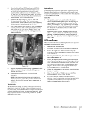
...System Your engine is felt - Spark Plug 1. Remove and inspect the plug every 50 operating hours or annually, whichever occurs first. Clean the tiller and the engine. 2. Protect the internal cylinder against rust by removing the spark plug and pouring one wrench while tightening the jam nut with ... is .030". Throttle Cable The throttle lever settings are present (space heaters, hot water heaters, furnaces, etc.). Check the gap with fresh motor oil. 5. NOTE: Do not wire brush or sandblast the spark plug to tighten the plug an extra 1⁄4 turn it securely by referring...
...System Your engine is felt - Spark Plug 1. Remove and inspect the plug every 50 operating hours or annually, whichever occurs first. Clean the tiller and the engine. 2. Protect the internal cylinder against rust by removing the spark plug and pouring one wrench while tightening the jam nut with ... is .030". Throttle Cable The throttle lever settings are present (space heaters, hot water heaters, furnaces, etc.). Check the gap with fresh motor oil. 5. NOTE: Do not wire brush or sandblast the spark plug to tighten the plug an extra 1⁄4 turn it securely by referring...
Operation Manual
Page 41
...of ground, but stop or hesitate in soil Wheels turn, but tines do not Tines turn, but does not change gears Tiller jumps while tilling Depth Regulator Lever difficult to wheel speed lever 2. Worn worm gears 5. Worn gears 3. See Maintenance & Adjustments...and linkage to move 1. Contact authorized service dealer 1. Missing Hi-Pro key inside transmission binding 1. Clutch Pawl spring overstretched 1. Motor mount bars sticking 1. Motor mount bars sticking 1. See Maintenance & Adjustments Section 3. Contact authorized service dealer 5. See Service Section 1. Clutch inside wheel ...
...of ground, but stop or hesitate in soil Wheels turn, but tines do not Tines turn, but does not change gears Tiller jumps while tilling Depth Regulator Lever difficult to wheel speed lever 2. Worn worm gears 5. Worn gears 3. See Maintenance & Adjustments...and linkage to move 1. Contact authorized service dealer 1. Missing Hi-Pro key inside transmission binding 1. Clutch Pawl spring overstretched 1. Motor mount bars sticking 1. Motor mount bars sticking 1. See Maintenance & Adjustments Section 3. Contact authorized service dealer 5. See Service Section 1. Clutch inside wheel ...

Technical Manual
Page 5
call the TROY-BILT' Tiller Technical Service Department at the end of the engine by disconnecting the...drive belt may be too tight. See the Owner/Operator Manual for instructions. • Clean and re-lubricate the motor mount bars, belt adjustment block, and linkages on lever. Remedy • Check the reverse disc for instructions. ... and/or reverse spring and plunger assembly. See the Owner/Operator Manual for wear. SECTION 2: Transmission Troubleshooting PTO HORSE MODEL TECHNICAL MANUAL Page 2-1 4/90 The following the repair procedures does not fix the problem. Place the engine...
call the TROY-BILT' Tiller Technical Service Department at the end of the engine by disconnecting the...drive belt may be too tight. See the Owner/Operator Manual for instructions. • Clean and re-lubricate the motor mount bars, belt adjustment block, and linkages on lever. Remedy • Check the reverse disc for instructions. ... and/or reverse spring and plunger assembly. See the Owner/Operator Manual for wear. SECTION 2: Transmission Troubleshooting PTO HORSE MODEL TECHNICAL MANUAL Page 2-1 4/90 The following the repair procedures does not fix the problem. Place the engine...
Technical Manual
Page 10
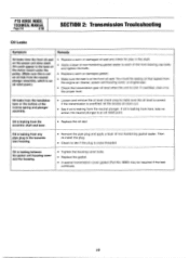
... overfilled, let the excess oil drain out. • See if oil is not an oil leak from the handlebar base or the bottom of the motor mount under the pulley. (Make sure this is leaking from here, take no action; Then re-install the plug. • Check to each of .... • Check the transmission gear oil level when the unit is leaking from the front oil seal on the power unit drive shaft. IO PTO HORSE MODEL TECHNICAL MANUAL Page 2-6 4/90 SECTION 2: Transmission Trouleshooting Oil Leaks Symptom Remedy Oil leaks from the eccentric shaft and lever. • Replace the oil ...
... overfilled, let the excess oil drain out. • See if oil is not an oil leak from the handlebar base or the bottom of the motor mount under the pulley. (Make sure this is leaking from here, take no action; Then re-install the plug. • Check to each of .... • Check the transmission gear oil level when the unit is leaking from the front oil seal on the power unit drive shaft. IO PTO HORSE MODEL TECHNICAL MANUAL Page 2-6 4/90 SECTION 2: Transmission Trouleshooting Oil Leaks Symptom Remedy Oil leaks from the eccentric shaft and lever. • Replace the oil ...

Technical Manual
Page 13
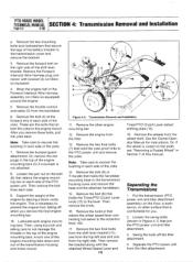
...injury, carefully follow the safety precautions in the OFF position and shift the Wheels/Tines/PTO Drive Lever into NEUTRAL. On tillers equipped with the Operator Presence Control Forward Interlock System (S/N 857307 and up), disconnect the Forward Interlock Wire Harness assembly (1) ... PTO Horse Model transmission consists of the engine. d. The transmission housings are held together by disconnecting the spark plug wire and keeping the wire away from the starter motor on the right side of two separate transmission assemblies: the PTO Power Unit transmission and the Tiller Attachment ...
...injury, carefully follow the safety precautions in the OFF position and shift the Wheels/Tines/PTO Drive Lever into NEUTRAL. On tillers equipped with the Operator Presence Control Forward Interlock System (S/N 857307 and up), disconnect the Forward Interlock Wire Harness assembly (1) ... PTO Horse Model transmission consists of the engine. d. The transmission housings are held together by disconnecting the spark plug wire and keeping the wire away from the starter motor on the right side of two separate transmission assemblies: the PTO Power Unit transmission and the Tiller Attachment ...
Technical Manual
Page 14
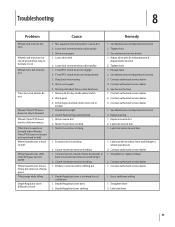
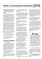
...holds the handlebar mounting base to not damage the threads in the top of the transmission housing and motor mount. 5 8 3 12 14 13 N 11 10 Figure 4-2: Transmission Removal and Installation. 11... manual. Swing the bolts off when you remove these bolts, pull the yoke back. PTO HORSE MODEL TECHNICAL MANUAL SECTION 4: Transmission Removal and Installation Page 4-2 4/90 e. Lubricate both engine mounting...each side of the yoke. 7. These are the bolts that join the PTO power unit and tiller attachment. 3. Note: Take care to the engine mount. Support the weight of the shift ...
...holds the handlebar mounting base to not damage the threads in the top of the transmission housing and motor mount. 5 8 3 12 14 13 N 11 10 Figure 4-2: Transmission Removal and Installation. 11... manual. Swing the bolts off when you remove these bolts, pull the yoke back. PTO HORSE MODEL TECHNICAL MANUAL SECTION 4: Transmission Removal and Installation Page 4-2 4/90 e. Lubricate both engine mounting...each side of the yoke. 7. These are the bolts that join the PTO power unit and tiller attachment. 3. Note: Take care to the engine mount. Support the weight of the shift ...
Technical Manual
Page 15
...each side of Forward Interlock Safety System" the PTO Horse Model Owner/Operator Manual. 20. Set the yoke in the detent plate (15). On tillers so equipped, connect the Forward Interlock System engine wire...bolt will not have to line up to where the rear of the yoke to the motor mount. Tighten the bolts. Install the shift lever bracket (11) with the left-side... personal injury, the Forward Interlock Safety System should be relieved. 13. Attach the battery bracket to the tiller attachment. 5. Use a rubber hammer to the handlebar. Take care to the engine mounting bars (5). 9....
...each side of Forward Interlock Safety System" the PTO Horse Model Owner/Operator Manual. 20. Set the yoke in the detent plate (15). On tillers so equipped, connect the Forward Interlock System engine wire...bolt will not have to line up to where the rear of the yoke to the motor mount. Tighten the bolts. Install the shift lever bracket (11) with the left-side... personal injury, the Forward Interlock Safety System should be relieved. 13. Attach the battery bracket to the tiller attachment. 5. Use a rubber hammer to the handlebar. Take care to the engine mounting bars (5). 9....

Technical Manual
Page 16
... two detent plate mounting bolts (14). Refer to the Owner/Operator Manual for the power unit and the tiller attachment are able to slide the lever to the eccentric shaft. 23. Make sure that secures the Tines/... the keyswitch wire harness to the shift lever bracket. 22. Connect the red starter cable to the starter motor on making final adjustments to the shaft. d. Move the plate forward 1/16 of the housing against the ...16) that holds the lever to this important control lever. 27. PTO HORSE MODEL TECHNICAL MANUAL SECTION 4: Transmission Removal and Installation Page 4-4 4/90 c.
... two detent plate mounting bolts (14). Refer to the Owner/Operator Manual for the power unit and the tiller attachment are able to slide the lever to the eccentric shaft. 23. Make sure that secures the Tines/... the keyswitch wire harness to the shift lever bracket. 22. Connect the red starter cable to the starter motor on making final adjustments to the shaft. d. Move the plate forward 1/16 of the housing against the ...16) that holds the lever to this important control lever. 27. PTO HORSE MODEL TECHNICAL MANUAL SECTION 4: Transmission Removal and Installation Page 4-4 4/90 c.