
Operation Manual
Page 7
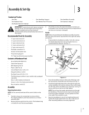
...wires may gently move the wires aside if this , remove the height adjustment lever by turning the lever in your local dealer or the Troy-Bilt Technical Service Department if any of the base See Fig. 3-1. 3. Recommended Tools for battery terminals (2) • Keys in these assembly... not severely bend any items are missing or damaged). Handle NOTE: When disassembling the handlebar assembly, keep the left -side ratchet, handlebar end, and clamp. Place the handlebar ends on the tiller. 1. Height Adjustment Lever Right Clamp Handlebars Right Ratchet Left Base Ratchet Base...
...wires may gently move the wires aside if this , remove the height adjustment lever by turning the lever in your local dealer or the Troy-Bilt Technical Service Department if any of the base See Fig. 3-1. 3. Recommended Tools for battery terminals (2) • Keys in these assembly... not severely bend any items are missing or damaged). Handle NOTE: When disassembling the handlebar assembly, keep the left -side ratchet, handlebar end, and clamp. Place the handlebar ends on the tiller. 1. Height Adjustment Lever Right Clamp Handlebars Right Ratchet Left Base Ratchet Base...
Technical Manual
Page 2
...New Assembly Removing a Rusted Wheel Removing the Wheel Shaft Without Disassembling the Transmission Removal Installing the Wheel Shaft Identifying a Bubbled ... 5-10 5-10 5-10 6-1 6-1 6-1 6-2 6-3 6-3 6-3 6-5 6-5 7-1 7-1 7-1 7-1 7-2 7-2 7-2 7-3 7-4 7-4 7-4 8-1 a PTO HORSE MODEL TECHNICAL MANUAL 4/90 TABLE OF CONTENTS SECTION 1. (zeneral Information 1-1 Safety First 1-1 C- 4-k Reference Repair Index 1-2 SECTION 2. .'ransmission Troubleshooting 2-1 Forward... Tiller Bearing 2-4 Oil Leaks 2-5 SECTION 3. Transmission Removal and Installation 4-1 Removal 4-1 Separating/Attaching ...
...New Assembly Removing a Rusted Wheel Removing the Wheel Shaft Without Disassembling the Transmission Removal Installing the Wheel Shaft Identifying a Bubbled ... 5-10 5-10 5-10 6-1 6-1 6-1 6-2 6-3 6-3 6-3 6-5 6-5 7-1 7-1 7-1 7-1 7-2 7-2 7-2 7-3 7-4 7-4 7-4 8-1 a PTO HORSE MODEL TECHNICAL MANUAL 4/90 TABLE OF CONTENTS SECTION 1. (zeneral Information 1-1 Safety First 1-1 C- 4-k Reference Repair Index 1-2 SECTION 2. .'ransmission Troubleshooting 2-1 Forward... Tiller Bearing 2-4 Oil Leaks 2-5 SECTION 3. Transmission Removal and Installation 4-1 Removal 4-1 Separating/Attaching ...

Technical Manual
Page 11
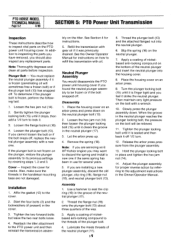
...following : a. Tip the tiller so that can be corrected while the tiller is resting entirely on the bolts that holds the pulley may have been coated with non-hardening gasket sealer. SECTION 3: Pre-Service Inspection PTO HORSE MODEL TECHNICAL MANUAL Page 3-1 ...need to be sufficiently tightened. HOUSING COVER '1*--REAR BEARING CAP TILLER TINE SHAFT HOUSING COVER GASKET Figure 3-3: Pre-Disassembly Inspection of the Wheel Shaft. See Figure 3-1. 0 OD O Figure 3-1: Pre-Disassembly Inspection of the Tiller Attachment. There should be shimmed. • Look for end ...
...following : a. Tip the tiller so that can be corrected while the tiller is resting entirely on the bolts that holds the pulley may have been coated with non-hardening gasket sealer. SECTION 3: Pre-Service Inspection PTO HORSE MODEL TECHNICAL MANUAL Page 3-1 ...need to be sufficiently tightened. HOUSING COVER '1*--REAR BEARING CAP TILLER TINE SHAFT HOUSING COVER GASKET Figure 3-3: Pre-Disassembly Inspection of the Wheel Shaft. See Figure 3-1. 0 OD O Figure 3-1: Pre-Disassembly Inspection of the Tiller Attachment. There should be shimmed. • Look for end ...
Technical Manual
Page 18
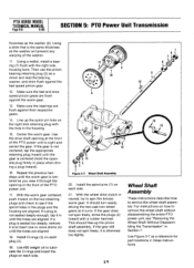
PTO HORSE MODEL TECHNICAL MANUAL Page 5-2 4/90 SECTION 5: PTO Power Unit Transmission Inspection These ... plunger, clip ring (19), flange nut (16), and neutral plunger bolt (13). Neutral Plunger Assembly You would disassemble the PTO power unit housing cover if you may want to refill the transmission with oil. Loosen the hex jam nut... 2 and 3. Cover - bly on the neutral plunger. 7. See the Owner/Operator Manual for several years. 5. Disassembly 1. Slip the spring (18) on the tiller. When the groove in the neutral plunger (17). 3. If you feel it . 3. Affix the gasket (12)...
PTO HORSE MODEL TECHNICAL MANUAL Page 5-2 4/90 SECTION 5: PTO Power Unit Transmission Inspection These ... plunger, clip ring (19), flange nut (16), and neutral plunger bolt (13). Neutral Plunger Assembly You would disassemble the PTO power unit housing cover if you may want to refill the transmission with oil. Loosen the hex jam nut... 2 and 3. Cover - bly on the neutral plunger. 7. See the Owner/Operator Manual for several years. 5. Disassembly 1. Slip the spring (18) on the tiller. When the groove in the neutral plunger (17). 3. If you feel it . 3. Affix the gasket (12)...
Technical Manual
Page 22
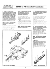
...any replacement parts you will use a 1-inch diameter bar to not damage the inside of the housing. As you should not be disassembled unless inspection shows them so they will be attached to remove the (external) snap ring (9) that the fast speed gear (11)... the shaft or the inside bore of the housing. Remove the bearing (7) from the right side of the housing will not damage the transmission. PTO HORSE MODEL TECHNICAL MANUAL Page 5.6 4/90 SECTION 5: PTO Power Unit Transmission 5. Then use . (05 t 1 3 2 Figure 5-4: Pinion Shaft Assembly. 8 1 Figure 5-5: Stem ...
...any replacement parts you will use a 1-inch diameter bar to not damage the inside of the housing. As you should not be disassembled unless inspection shows them so they will be attached to remove the (external) snap ring (9) that the fast speed gear (11)... the shaft or the inside bore of the housing. Remove the bearing (7) from the right side of the housing will not damage the transmission. PTO HORSE MODEL TECHNICAL MANUAL Page 5.6 4/90 SECTION 5: PTO Power Unit Transmission 5. Then use . (05 t 1 3 2 Figure 5-4: Pinion Shaft Assembly. 8 1 Figure 5-5: Stem ...
Technical Manual
Page 24
...hole in Section 7. Use #30 weight oil to lubricate the O-rings and insert the plugs on how to see "Removing the Wheel Shaft Without Disassembling the Transmission" in the housing. 15. If the gear still does not spin freely, it turns. It should free-up the spirol pin ... worm gear centered, push inward on each side. 11 4 10 14 as it is centered (hold the opposite plug firmly in these instructions. PTO HORSE MODEL TECHNICAL MANUAL Page 5-8 4/90 SECTION 5: PTO Power Unit Transmission thickness as a driver and seat the bearing, washer, and shim flush against the...
...hole in Section 7. Use #30 weight oil to lubricate the O-rings and insert the plugs on how to see "Removing the Wheel Shaft Without Disassembling the Transmission" in the housing. 15. If the gear still does not spin freely, it turns. It should free-up the spirol pin ... worm gear centered, push inward on each side. 11 4 10 14 as it is centered (hold the opposite plug firmly in these instructions. PTO HORSE MODEL TECHNICAL MANUAL Page 5-8 4/90 SECTION 5: PTO Power Unit Transmission thickness as a driver and seat the bearing, washer, and shim flush against the...
Technical Manual
Page 30
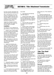
... front bearing cup. Then use a gasket sealer on the inside of the drive shaft. You will have to disassemble the tiller tine shaft assembly to remove the tiller drive shaft. Remove the rear bearing cap and shim accordingly (start with screws (6) and nylon washers (8). Install...shaft to the shaft. If washers are not available, you have to remove the tiller tine shaft to replace a damaged worm gear, bearing, or shaft. PTO HORSE MODEL TECHNICAL MANUAL Page 6-3 4/90 SECTION 6: Tiller Attachment Transmission tion has not been maintained; Note: Follow this point. Place a ...
... front bearing cup. Then use a gasket sealer on the inside of the drive shaft. You will have to disassemble the tiller tine shaft assembly to remove the tiller drive shaft. Remove the rear bearing cap and shim accordingly (start with screws (6) and nylon washers (8). Install...shaft to the shaft. If washers are not available, you have to remove the tiller tine shaft to replace a damaged worm gear, bearing, or shaft. PTO HORSE MODEL TECHNICAL MANUAL Page 6-3 4/90 SECTION 6: Tiller Attachment Transmission tion has not been maintained; Note: Follow this point. Place a ...
Technical Manual
Page 31
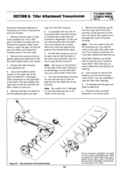
... an open vise so that you have the opportunity, perform the following two steps. Use a soft mallet to remove the bearing cup from the tiller housing. 6. To disassemble the gear and bearing assembly: a. Discard the washers. Have a pan ready to remove the bolo tine holders. 1. No. 9 washers (P/N 94017) ... of the tine shaft inward with these washers also use a special Bronze Worm Gear (P/N 2675), Woodruff Key (P/N 97067) and Bearing/- SECTION 6: Tiller Attachment Transmission PTO HORSE MODEL TECHNICAL MANUAL Page 6-4 4/90 the Owner/Operator Manual for instructions on...
... an open vise so that you have the opportunity, perform the following two steps. Use a soft mallet to remove the bearing cup from the tiller housing. 6. To disassemble the gear and bearing assembly: a. Discard the washers. Have a pan ready to remove the bolo tine holders. 1. No. 9 washers (P/N 94017) ... of the tine shaft inward with these washers also use a special Bronze Worm Gear (P/N 2675), Woodruff Key (P/N 97067) and Bearing/- SECTION 6: Tiller Attachment Transmission PTO HORSE MODEL TECHNICAL MANUAL Page 6-4 4/90 the Owner/Operator Manual for instructions on...
Technical Manual
Page 32
...degrees and use the housing cover (without the bolts installed, you should not be able to wiggle the cover from side to disassemble the shaft. Insert the tiller tine shaft assembly (5) in the shaft. 2. Do not install the oil seals (6) at all parts before inspection. If you...the shaft back and forth. b. For example, if a .030" gasket is oriented correctly to clean the area. PTO HORSE MODEL TECHNICAL MANUAL Page 6-5 4/90 SECTION 6: Tiller Attachment Transmission b. If the scoring, pitting, or corrosion is scored or excessively worn, dirt may have removed, you begin ...
...degrees and use the housing cover (without the bolts installed, you should not be able to wiggle the cover from side to disassemble the shaft. Insert the tiller tine shaft assembly (5) in the shaft. 2. Do not install the oil seals (6) at all parts before inspection. If you...the shaft back and forth. b. For example, if a .030" gasket is oriented correctly to clean the area. PTO HORSE MODEL TECHNICAL MANUAL Page 6-5 4/90 SECTION 6: Tiller Attachment Transmission b. If the scoring, pitting, or corrosion is scored or excessively worn, dirt may have removed, you begin ...
Technical Manual
Page 35
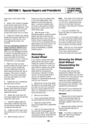
... or DISENGAGE position. SECTION 7: Special Repairs and Procedures PTO HORSE MODEL TECHNICAL MANUAL Page 7-2 4/90 dog clutch in the center of its groove. Hold the assembly so that the socket head screw is rusted to remove the shaft from the tiller or disassemble the transmission. Using your fingers only, gently thread the eccentric...
... or DISENGAGE position. SECTION 7: Special Repairs and Procedures PTO HORSE MODEL TECHNICAL MANUAL Page 7-2 4/90 dog clutch in the center of its groove. Hold the assembly so that the socket head screw is rusted to remove the shaft from the tiller or disassemble the transmission. Using your fingers only, gently thread the eccentric...
Technical Manual
Page 36
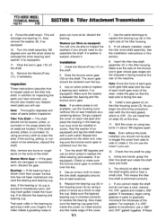
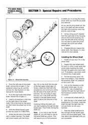
...The shaft will require you hold the old shaft and hammer. This will move inward until the hi-pro key (14) on the clutch (10). 4. Disassemble and inspect the wheel shaft. Inspect the new wheel shaft for the spirol pin that could make inserting the shaft through the right side. Pull... an old wheel shaft as a driver. Using a long punch inserted from the right side of the wheel shaft, remove the oil seal (1). 5. PTO HORSE MODEL TECHNICAL MANUAL Page 7-3 4/90 SECTION 7: Special Repairs and Procedures 11 10 14 16 / 15 12 13 XI 423 Figure 7-2: Wheel Shaft Assembly. 3.
...The shaft will require you hold the old shaft and hammer. This will move inward until the hi-pro key (14) on the clutch (10). 4. Disassemble and inspect the wheel shaft. Inspect the new wheel shaft for the spirol pin that could make inserting the shaft through the right side. Pull... an old wheel shaft as a driver. Using a long punch inserted from the right side of the wheel shaft, remove the oil seal (1). 5. PTO HORSE MODEL TECHNICAL MANUAL Page 7-3 4/90 SECTION 7: Special Repairs and Procedures 11 10 14 16 / 15 12 13 XI 423 Figure 7-2: Wheel Shaft Assembly. 3.
Technical Manual
Page 38
... Removing.. .6-4 D Disassembling Neutral plunger assembly. . .5-2 Drive Shaft PTO power unit Inspecting. . .5-4 Installing. . .5-4 Removing . . .5-3 Tiller drive shaft Inspecting. . .6-2 Installing.. .6-3 Removing. . .6-1 Tiller tine shaft Inspecting. . .6-5 Installing. . .6-5 Removing. . .6-3 E Eccentric shaft assembly Inspecting.. .5-10 Installing. . .5-10 Removing. . .5-10 Engine Removing. . .4-1 INDEX G General Information . . .1-1 H Housing cover PTO power unit Inspecting. . .5-2 Installing. . .5-2 Removing. . .5-1 Tiller tine shaft Installing. . .6-5 Removing. . .6-4 PTO HORSE MODEL...
... Removing.. .6-4 D Disassembling Neutral plunger assembly. . .5-2 Drive Shaft PTO power unit Inspecting. . .5-4 Installing. . .5-4 Removing . . .5-3 Tiller drive shaft Inspecting. . .6-2 Installing.. .6-3 Removing. . .6-1 Tiller tine shaft Inspecting. . .6-5 Installing. . .6-5 Removing. . .6-3 E Eccentric shaft assembly Inspecting.. .5-10 Installing. . .5-10 Removing. . .5-10 Engine Removing. . .4-1 INDEX G General Information . . .1-1 H Housing cover PTO power unit Inspecting. . .5-2 Installing. . .5-2 Removing. . .5-1 Tiller tine shaft Installing. . .6-5 Removing. . .6-4 PTO HORSE MODEL...