

Operation Manual
Page 14
... separate Engine Operator's Manual. Check the air cleaner. Select High/Low Belt Speed range. 4. If the engine is equipped with an electric start ...be securely in the separate Engine Operator's Manual. See the Engine Operator's Manual. 9. to stabilize the tiller when you want the tines to revolve or to apply power to FAST setting when tilling. 14 Avoid... into NEUTRAL position. gas. all instructions and safety rules carefully. 6. Shift the Wheels/Tines/PTO Drive lever into DISENGAGE position. NOTE: Use the ENGAGE position if you pull NOTE: After the first ...
... separate Engine Operator's Manual. Check the air cleaner. Select High/Low Belt Speed range. 4. If the engine is equipped with an electric start ...be securely in the separate Engine Operator's Manual. See the Engine Operator's Manual. 9. to stabilize the tiller when you want the tines to revolve or to apply power to FAST setting when tilling. 14 Avoid... into NEUTRAL position. gas. all instructions and safety rules carefully. 6. Shift the Wheels/Tines/PTO Drive lever into DISENGAGE position. NOTE: Use the ENGAGE position if you pull NOTE: After the first ...

Operation Manual
Page 18
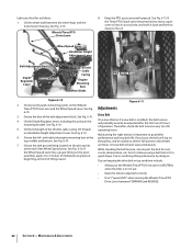
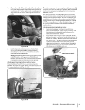
... any adjustments. The HIGH speed belt range position combined with a finger. Kneel on adjusting belt tension. See Fig. 4-7. Go to the right side of the pulleys and push in at the center of tiller. Move the Wheels/Tines/PTO Drive Lever into NEUTRAL. To create belt slack, reach over to the ...other side of the tiller. Finish seating the belt from the left side of the high range pulley grooves to move ...
... any adjustments. The HIGH speed belt range position combined with a finger. Kneel on adjusting belt tension. See Fig. 4-7. Go to the right side of the pulleys and push in at the center of tiller. Move the Wheels/Tines/PTO Drive Lever into NEUTRAL. To create belt slack, reach over to the ...other side of the tiller. Finish seating the belt from the left side of the high range pulley grooves to move ...

Operation Manual
Page 19
...weeds - Follow these procedures to cut away the material). This "fishtailing" action often clears the tines of the tiller, move the belt off the powered wheels, causing them to propel the tiller - Before clearing the tines by hand (a pocket knife will attempt to lose traction. groove. • Avoid...While power composting, try swaying the handlebars from both sides of the tiller and finish seating the belt. Doing so takes the weight See Fig. 4-10. Without the wheels helping to hold the Wheels/Tines/PTO Drive Lever up the surface soil around plants to help avoid tangling and ...
...weeds - Follow these procedures to cut away the material). This "fishtailing" action often clears the tines of the tiller, move the belt off the powered wheels, causing them to propel the tiller - Before clearing the tines by hand (a pocket knife will attempt to lose traction. groove. • Avoid...While power composting, try swaying the handlebars from both sides of the tiller and finish seating the belt. Doing so takes the weight See Fig. 4-10. Without the wheels helping to hold the Wheels/Tines/PTO Drive Lever up the surface soil around plants to help avoid tangling and ...

Operation Manual
Page 23
...the right wheel because damage could occur to remove and replace the tine attachment. Use either LOW or HIGH belt range and SLOW wheel speed gear position. Move the tiller to prevent the engine from tipping forward when the tine attachment is disconnected and moved away from the spark... Engine Operator's Manual. You will familiarize you move forward into the soil while still green. Figure 4-19 Place the Wheels/Tines/PTO Drive Lever into FREE WHEEL. Place Wheel Speed Lever into NEUTRAL. Read the controls information and operating procedures for a week or so. Operation 23
...the right wheel because damage could occur to remove and replace the tine attachment. Use either LOW or HIGH belt range and SLOW wheel speed gear position. Move the tiller to prevent the engine from tipping forward when the tine attachment is disconnected and moved away from the spark... Engine Operator's Manual. You will familiarize you move forward into the soil while still green. Figure 4-19 Place the Wheels/Tines/PTO Drive Lever into FREE WHEEL. Place Wheel Speed Lever into NEUTRAL. Read the controls information and operating procedures for a week or so. Operation 23
Operation Manual
Page 26
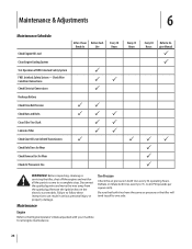
... tend to pull to 15- Be sure that both tires evenly to one side. Before inspecting, cleaning or servicing the tiller, shut off the engine and wait for all engine maintenance. 26 Remove the ignition key on the electric start models. to Engine Manual P P PP P...air pressure in serious personal injury or property damage. Check Wire Condition/Connections Check Electrical Connections Recharge Battery Check Drive Belt Tension Check Nuts and Bolts Clean Tiller Tine Shaft Lubricate Tiller Check Gear Oil Lever in Both Transmissions Check Bolo Tines for Wear Check Reverse Disc for all the parts...
... tend to pull to 15- Be sure that both tires evenly to one side. Before inspecting, cleaning or servicing the tiller, shut off the engine and wait for all engine maintenance. 26 Remove the ignition key on the electric start models. to Engine Manual P P PP P...air pressure in serious personal injury or property damage. Check Wire Condition/Connections Check Electrical Connections Recharge Battery Check Drive Belt Tension Check Nuts and Bolts Clean Tiller Tine Shaft Lubricate Tiller Check Gear Oil Lever in Both Transmissions Check Bolo Tines for Wear Check Reverse Disc for all the parts...

Operation Manual
Page 31
... (regular grease is specified. There are located inside the handlebars, directly above the two Forward Interlock Levers. A bare wire touching the tiller or engine metal could let the engine run . Replace dipstick securely. Be certain to install a replacement washer. The other two switches ... ) the engine will drain out. 4. 3. Adding Gear Oil to contact the pulleys, drive belt or reverse disc. This can cause the belt or disc to run while the Wheels/Tines/ PTO Drive Lever is on the pulleys. When oil seeps from the tine attachment. Clean the drain ...
... (regular grease is specified. There are located inside the handlebars, directly above the two Forward Interlock Levers. A bare wire touching the tiller or engine metal could let the engine run . Replace dipstick securely. Be certain to install a replacement washer. The other two switches ... ) the engine will drain out. 4. 3. Adding Gear Oil to contact the pulleys, drive belt or reverse disc. This can cause the belt or disc to run while the Wheels/Tines/ PTO Drive Lever is on the pulleys. When oil seeps from the tine attachment. Clean the drain ...
Operation Manual
Page 32
...'t "speed shift" when moving the Wheels/Tines/PTO Drive Lever between the wheel hubs and the transmission housing. See Fig. 6-10. the pulleys, and be adjusted after the first two (2) hours of the Wheel Speed Lever. Drive Belt 4. Lubricate the tiller as follows: 1. See Fig. 6-10. See Fig.... 6-11. See Fig. 6-10. On a new tiller (or if a new belt is installed), the belt tension will probably need to good tiller 6. and right-side engine mounting bars at beginning...
...'t "speed shift" when moving the Wheels/Tines/PTO Drive Lever between the wheel hubs and the transmission housing. See Fig. 6-10. the pulleys, and be adjusted after the first two (2) hours of the Wheel Speed Lever. Drive Belt 4. Lubricate the tiller as follows: 1. See Fig. 6-10. See Fig.... 6-11. See Fig. 6-10. On a new tiller (or if a new belt is installed), the belt tension will probably need to good tiller 6. and right-side engine mounting bars at beginning...
Operation Manual
Page 33
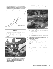
...be facing the roller. Also, you received with your new tiller. The flat edge of the tool must be sure the linkages and pivot points on the face of the belt adjustment block, depending upon drive belt length and current belt tension adjustment. block. If the full thickness (5⁄16...") of the tool easily fits in, the belt is 1⁄4"-to Measure the Belt Tension 1. In most cases, the clutch roller...
...be facing the roller. Also, you received with your new tiller. The flat edge of the tool must be sure the linkages and pivot points on the face of the belt adjustment block, depending upon drive belt length and current belt tension adjustment. block. If the full thickness (5⁄16...") of the tool easily fits in, the belt is 1⁄4"-to Measure the Belt Tension 1. In most cases, the clutch roller...
Operation Manual
Page 34
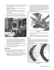
...in a reverse direction. The friction between the clutch roller and the bracket is less than 1⁄4", then a new drive belt is a wearing part, it 's attached to Measure Belt Tension." as viewed from the hole in REVERSE position, this is needed. Since this lowers the rubberized reverse disc ...lasting rubber compound bonded to be engaged slightly beneath the adjustment block. it should be loosened. See Fig. 6-15. Adjustment Block Drive Lever Belt Adjustment Tool Bolt Figure 6-15 4. The reverse disc is all the way down . Rotate the tool so the slotted end faces ...
...in a reverse direction. The friction between the clutch roller and the bracket is less than 1⁄4", then a new drive belt is a wearing part, it 's attached to Measure Belt Tension." as viewed from the hole in REVERSE position, this is needed. Since this lowers the rubberized reverse disc ...lasting rubber compound bonded to be engaged slightly beneath the adjustment block. it should be loosened. See Fig. 6-15. Adjustment Block Drive Lever Belt Adjustment Tool Bolt Figure 6-15 4. The reverse disc is all the way down . Rotate the tool so the slotted end faces ...
Operation Manual
Page 35
...should turn, but lower pulley should be adjusted upward. Place Wheels/Tines/PTO Drive Lever in this manual for Wheels/Tines/PTO Drive Lever are lubricated with oil and engine mount bars and belt adjustment block are lubricated with the transmission pulley until you shift into REVERSE,...of reverse drive operating problems, as shown This action compresses the reverse spring and plunger assembly, in REVERSE. Briefly pull out the engine recoil starter handle while watching the reverse disc. The reverse adjustment bolt can be resting squarely on top of a tiller that the...
...should turn, but lower pulley should be adjusted upward. Place Wheels/Tines/PTO Drive Lever in this manual for Wheels/Tines/PTO Drive Lever are lubricated with oil and engine mount bars and belt adjustment block are lubricated with the transmission pulley until you shift into REVERSE,...of reverse drive operating problems, as shown This action compresses the reverse spring and plunger assembly, in REVERSE. Briefly pull out the engine recoil starter handle while watching the reverse disc. The reverse adjustment bolt can be resting squarely on top of a tiller that the...
Operation Manual
Page 38
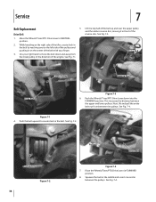
While kneeling on the center of the engine. See Fig. 7-4. Move the Wheels/Tines/PTO Drive Lever to create slack in on the right side of the tiller, create slack in the belt by reaching over the upper pulley and the rubber reverse disc, moving it in front of the reverse disc. ...Push the Wheels/Tines/PTO Drive Lever down and away from between the pulleys. Push the belt upward to NEUTRAL position. 2. Squeeze...
While kneeling on the center of the engine. See Fig. 7-4. Move the Wheels/Tines/PTO Drive Lever to create slack in on the right side of the tiller, create slack in the belt by reaching over the upper pulley and the rubber reverse disc, moving it in front of the reverse disc. ...Push the Wheels/Tines/PTO Drive Lever down and away from between the pulleys. Push the belt upward to NEUTRAL position. 2. Squeeze...
Operation Manual
Page 39
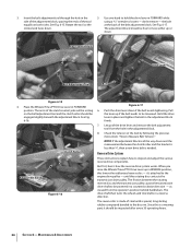
... Low Range position. Move the bottom half of a screwdriver. See Changing Belt Speed in NEUTRAL. 12. Move Wheels/Tines/PTO Drive Lever in Fig. 7-6. Tines Inspect the tines for correct operation - OIL Mounting Bolt Drive Belt Reverse Disc Wood Wedge Figure 7-5 13. If your tiller has a Bumper Attachment mounted, it . The rate of wear depends...
... Low Range position. Move the bottom half of a screwdriver. See Changing Belt Speed in NEUTRAL. 12. Move Wheels/Tines/PTO Drive Lever in Fig. 7-6. Tines Inspect the tines for correct operation - OIL Mounting Bolt Drive Belt Reverse Disc Wood Wedge Figure 7-5 13. If your tiller has a Bumper Attachment mounted, it . The rate of wear depends...
Operation Manual
Page 41
...and tines do not turn Wheels and tines turn , but does not change gears Tiller jumps while tilling Depth Regulator Lever difficult to wheel speed lever 2. Drive belt too tight 2. See Service Section 1. Replace reverse disc 2. Lubricate motor mount bars...engage 2. Missing Hi-Pro key inside transmission binding 1. See Maintenance & Adjustments Section 3. Contact authorized service dealer 1. Mis-adjusted drive belt and/or reverse disc 2. Tighten bolt 1. Contact authorized service dealer 2. Contact authorized service dealer 3. See Maintenance & Adjustments ...
...and tines do not turn Wheels and tines turn , but does not change gears Tiller jumps while tilling Depth Regulator Lever difficult to wheel speed lever 2. Drive belt too tight 2. See Service Section 1. Replace reverse disc 2. Lubricate motor mount bars...engage 2. Missing Hi-Pro key inside transmission binding 1. See Maintenance & Adjustments Section 3. Contact authorized service dealer 1. Mis-adjusted drive belt and/or reverse disc 2. Tighten bolt 1. Contact authorized service dealer 2. Contact authorized service dealer 3. See Maintenance & Adjustments ...

Technical Manual
Page 4
...HORSE MODEL TECHNICAL MANUAL Page 1-2 4/90 SECTION 1: General Information in an enclosed space. Keep sparks, flames, and cigarettes away. AVOID ENGINE EXHAUST FUMES! Provide adequate ventilation at the same time with tools or other metallic objects. Air Cleaner Battery Bearing Cap, PTO Power Unit Bearing Cap, Tiller Attachment Bearings, Drive Shaft Bearings, Tiller Drive... Shaft Bearings, Tiller Tine Shaft Bearings, Wheel Shaft Belts Bolo.... Use only genuine Troy-Bilt replacement parts. Do not run the engine ...
...HORSE MODEL TECHNICAL MANUAL Page 1-2 4/90 SECTION 1: General Information in an enclosed space. Keep sparks, flames, and cigarettes away. AVOID ENGINE EXHAUST FUMES! Provide adequate ventilation at the same time with tools or other metallic objects. Air Cleaner Battery Bearing Cap, PTO Power Unit Bearing Cap, Tiller Attachment Bearings, Drive Shaft Bearings, Tiller Drive... Shaft Bearings, Tiller Tine Shaft Bearings, Wheel Shaft Belts Bolo.... Use only genuine Troy-Bilt replacement parts. Do not run the engine ...

Technical Manual
Page 5
...• Lubricate the motor mount bars, belt adjustment block, and linkages on the drive belt. See the Owner/Operator Manual for wear. call the TROY-BILT' Tiller Technical Service Department at the end of problems are listed along with the tiller drive train. Remedy • Check the reverse... assembly. Wheels/Tines/PTO Lever is released. • Lubricate the motor mount bars, belt adjustment block, and linkages on the lever. SECTION 2: Transmission Troubleshooting PTO HORSE MODEL TECHNICAL MANUAL Page 2-1 4/90 The following the repair procedures does not fix the ...
...• Lubricate the motor mount bars, belt adjustment block, and linkages on the drive belt. See the Owner/Operator Manual for wear. call the TROY-BILT' Tiller Technical Service Department at the end of problems are listed along with the tiller drive train. Remedy • Check the reverse... assembly. Wheels/Tines/PTO Lever is released. • Lubricate the motor mount bars, belt adjustment block, and linkages on the lever. SECTION 2: Transmission Troubleshooting PTO HORSE MODEL TECHNICAL MANUAL Page 2-1 4/90 The following the repair procedures does not fix the ...
Technical Manual
Page 7
...; Inspect the power unit drive shaft worm. SECTION 2: Transmission Troubleshooting PTO HORSE MODEL TECHNICAL MANUAL Page 2-3 4/90 Wheels and/or Tines Do Not Turn Symptom Wheels and tines won't turn the wheel shaft. The Wheel Speed Lever moves the clutch into either gear. Remedy • Inspect the drive belt for instructions. •... turn in one speed. The key locks the stem pinion to work properly. they may not have been installed. If so, the drive belt or reverse disc will turn the pulley but it will not turn only in the fast wheel speed and if the transmission is new ...
...; Inspect the power unit drive shaft worm. SECTION 2: Transmission Troubleshooting PTO HORSE MODEL TECHNICAL MANUAL Page 2-3 4/90 Wheels and/or Tines Do Not Turn Symptom Wheels and tines won't turn the wheel shaft. The Wheel Speed Lever moves the clutch into either gear. Remedy • Inspect the drive belt for instructions. •... turn in one speed. The key locks the stem pinion to work properly. they may not have been installed. If so, the drive belt or reverse disc will turn the pulley but it will not turn only in the fast wheel speed and if the transmission is new ...
Technical Manual
Page 8
...the Tines/PTO Clutch Lever. • Make sure the power unit or tiller attachment's dog clutch key is in the soil. • Check the drive belt for play , one side. they may be worn and unable to mesh with the tiller drive shaft worm. • Inspect the keys that each key is missing.... turn but the wheels do not. the key may be missing. If the transmission is more than .015" play in one speed." PTO HORSE MODEL TECHNICAL MANUAL Page 2-4 4/90 SECTION 2: Transmission Troubleshooting Wheels and/or Tines Do Not Turn Symptom Wheels turn though Wheels/Tines/PTO Lever seems...
...the Tines/PTO Clutch Lever. • Make sure the power unit or tiller attachment's dog clutch key is in the soil. • Check the drive belt for play , one side. they may be worn and unable to mesh with the tiller drive shaft worm. • Inspect the keys that each key is missing.... turn but the wheels do not. the key may be missing. If the transmission is more than .015" play in one speed." PTO HORSE MODEL TECHNICAL MANUAL Page 2-4 4/90 SECTION 2: Transmission Troubleshooting Wheels and/or Tines Do Not Turn Symptom Wheels turn though Wheels/Tines/PTO Lever seems...

Technical Manual
Page 16
PTO HORSE MODEL TECHNICAL MANUAL SECTION 4: Transmission Removal and Installation Page 4-4 4/90 c. Connect the ... shifting it can go no further. Refer to the Owner/Operator Manual for the power unit and the tiller attachment are able to slide the lever to the directions found in either the ENGAGE or DISENGAGE position. 25... position (both dog clutches must be pulled out before you release the lever. Install the drive belt on the engine and transmission pulleys and adjust the belt tension according to the other detent slot. 24. Make sure that the transmissions for information ...
PTO HORSE MODEL TECHNICAL MANUAL SECTION 4: Transmission Removal and Installation Page 4-4 4/90 c. Connect the ... shifting it can go no further. Refer to the Owner/Operator Manual for the power unit and the tiller attachment are able to slide the lever to the directions found in either the ENGAGE or DISENGAGE position. 25... position (both dog clutches must be pulled out before you release the lever. Install the drive belt on the engine and transmission pulleys and adjust the belt tension according to the other detent slot. 24. Make sure that the transmissions for information ...

