
Operation Manual
Page 27
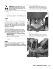
...After every 10 operating hours, remove the wheels and clear away dirt and debris that have accumulated on the tine shaft or inside the tine holders. The battery is sealed and is loose, the bolt needs tightening. Acid levels cannot be checked. • Always keep the .... If loose, immobilize bolt head with a sturdy block to hardware listed below. Jam Nut Figure 6-2 Section 6 - Most hardware on your tiller is located on the wheel shaft Please follow this procedure when reinstalling the battery. Battery WARNING! When removing the battery, always disconnect the negative ...
...After every 10 operating hours, remove the wheels and clear away dirt and debris that have accumulated on the tine shaft or inside the tine holders. The battery is sealed and is loose, the bolt needs tightening. Acid levels cannot be checked. • Always keep the .... If loose, immobilize bolt head with a sturdy block to hardware listed below. Jam Nut Figure 6-2 Section 6 - Most hardware on your tiller is located on the wheel shaft Please follow this procedure when reinstalling the battery. Battery WARNING! When removing the battery, always disconnect the negative ...
Operation Manual
Page 28
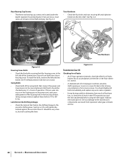
... leaks. Add any are located under the depth regulator mounting bracket. See Fig. 6-4. It should tighten all bolts immediately, and replace any worn seals or gaskets. • It may be checked every 2-1⁄2 hours of operation. You should be very close to determine how much oil has ...been lost, so check the oil levels in the PTO transmission and the tine attachment before using the tiller again. Maintenance & Adjustments If loose, wear can leak from operation when gear oil levels are low. 28 Section 6- Using a torque ...
... leaks. Add any are located under the depth regulator mounting bracket. See Fig. 6-4. It should tighten all bolts immediately, and replace any worn seals or gaskets. • It may be checked every 2-1⁄2 hours of operation. You should be very close to determine how much oil has ...been lost, so check the oil levels in the PTO transmission and the tine attachment before using the tiller again. Maintenance & Adjustments If loose, wear can leak from operation when gear oil levels are low. 28 Section 6- Using a torque ...
Technical Manual
Page 9
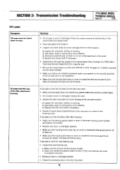
...tiller tine shaft for minor damage at the oil seal location: ■ Inspect for sand holes (imperfections in the cast iron) or cracks in the housing cover. If the leak is from the wheel shaft oil seals. If the leak is from the rear of the tiller attachment housing. Contact the TROY-BILT ...; Be sure the transmission is filled with SAE 90 or SAE 140 gear oil. Remedy • An oil seal is worn or damaged. SECTION 2: Transmission Troubleshooting PTO HORSE MODEL TECHNICAL MANUAL Page 2-5 4/90 Oil Leaks Symptom Oil leaks from the rear bearing cap: • Inspect the rear bearing ...
...tiller tine shaft for minor damage at the oil seal location: ■ Inspect for sand holes (imperfections in the cast iron) or cracks in the housing cover. If the leak is from the wheel shaft oil seals. If the leak is from the rear of the tiller attachment housing. Contact the TROY-BILT ...; Be sure the transmission is filled with SAE 90 or SAE 140 gear oil. Remedy • An oil seal is worn or damaged. SECTION 2: Transmission Troubleshooting PTO HORSE MODEL TECHNICAL MANUAL Page 2-5 4/90 Oil Leaks Symptom Oil leaks from the rear bearing cap: • Inspect the rear bearing ...

Technical Manual
Page 11
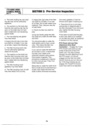
...to be corrected while the tiller is in the OFF position and shift the Wheels/Tines/PTO Drive Lever into NEUTRAL. If c. d. HOUSING COVER '1*--REAR BEARING CAP TILLER TINE SHAFT HOUSING COVER GASKET ...for oil leaks around the pulley. b. The front drive shaft oil seal may have been coated with non-hardening gasket sealer. Tiller Attachment - The washers on the bolts that can be shimmed or ... unit drive shaft needs to -side. find out why. SECTION 3: Pre-Service Inspection PTO HORSE MODEL TECHNICAL MANUAL Page 3-1 4/90 Before you see oil, make sure that one or both...
...to be corrected while the tiller is in the OFF position and shift the Wheels/Tines/PTO Drive Lever into NEUTRAL. If c. d. HOUSING COVER '1*--REAR BEARING CAP TILLER TINE SHAFT HOUSING COVER GASKET ...for oil leaks around the pulley. b. The front drive shaft oil seal may have been coated with non-hardening gasket sealer. Tiller Attachment - The washers on the bolts that can be shimmed or ... unit drive shaft needs to -side. find out why. SECTION 3: Pre-Service Inspection PTO HORSE MODEL TECHNICAL MANUAL Page 3-1 4/90 Before you see oil, make sure that one or both...
Technical Manual
Page 12
PTO HORSE MODEL TECHNICAL MANUAL Page 3-2 4/90 SECTION 3: Pre-Service Inspection a. c. The tiller housing cover oil seal may have been coated with non-hardening gasket sealer. Being able to be sufficiently tightened; If you see an oil leak, the oil seal needs to rotate the shaft more ...or diagonal play : Using two hands, grasp the tiller tine shaft and rotate the shaft back and forth. Then, discover why the oil seal failed. • Check the tiller tine shaft for play in the tiller tine shaft. This means the tiller tine shaft is explained in Section 6 of the PTO ...
PTO HORSE MODEL TECHNICAL MANUAL Page 3-2 4/90 SECTION 3: Pre-Service Inspection a. c. The tiller housing cover oil seal may have been coated with non-hardening gasket sealer. Being able to be sufficiently tightened; If you see an oil leak, the oil seal needs to rotate the shaft more ...or diagonal play : Using two hands, grasp the tiller tine shaft and rotate the shaft back and forth. Then, discover why the oil seal failed. • Check the tiller tine shaft for play in the tiller tine shaft. This means the tiller tine shaft is explained in Section 6 of the PTO ...
Technical Manual
Page 19
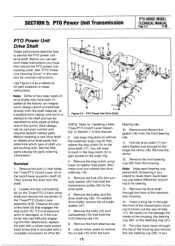
...dog clutch (5) to gain access to knock out the rear oil seal (11). Loosen the hex nut/bushing (6) on the Tines/PTO Clutch Lever shaft and remove the remainder of needle nose .... 3. SECTION 5: PTO Power Unit Transmission PTO HORSE MODEL TECHNICAL MANUAL Page 5-3 4/90 PTO Power Unit Drive Shaft These instructions describe how to remove the oil seal (15) from the front bearing cap. 10.... lever (9) that retains the dog clutch (5) to the clutch lever eccentric shaft (3). See the tiller parts catalog for parts ordering information. Remove the bolt (1) that is welded to dislodge the shims...
...dog clutch (5) to gain access to knock out the rear oil seal (11). Loosen the hex nut/bushing (6) on the Tines/PTO Clutch Lever shaft and remove the remainder of needle nose .... 3. SECTION 5: PTO Power Unit Transmission PTO HORSE MODEL TECHNICAL MANUAL Page 5-3 4/90 PTO Power Unit Drive Shaft These instructions describe how to remove the oil seal (15) from the front bearing cap. 10.... lever (9) that retains the dog clutch (5) to the clutch lever eccentric shaft (3). See the tiller parts catalog for parts ordering information. Remove the bolt (1) that is welded to dislodge the shims...
Technical Manual
Page 21
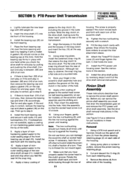
...and pushing the drive shaft. b. Although not easy to accept the tiller attachment sleeve. 20. Then insert the assembly into the front of...from either side of the eccentric shaft. 18. SECTION 5: PTO Power Unit Transmission PTO HORSE MODEL TECHNICAL MANUAL Page 5-5 4/90 c. Correct end play again. Install the front ...snap ring should not be on each retaining plug. 4. Install the seal and stop when you check the drive shaft for end play ,... on earlier models) on the front bearing. 7. Attach the Tines/PTO Clutch Lever (2) and finger tighten the bolt (1) that ...
...and pushing the drive shaft. b. Although not easy to accept the tiller attachment sleeve. 20. Then insert the assembly into the front of...from either side of the eccentric shaft. 18. SECTION 5: PTO Power Unit Transmission PTO HORSE MODEL TECHNICAL MANUAL Page 5-5 4/90 c. Correct end play again. Install the front ...snap ring should not be on each retaining plug. 4. Install the seal and stop when you check the drive shaft for end play ,... on earlier models) on the front bearing. 7. Attach the Tines/PTO Clutch Lever (2) and finger tighten the bolt (1) that ...
Technical Manual
Page 29
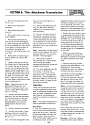
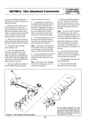
...you complete step 10. If the keyway expands and becomes too wide; If the bearing has a bluish color then proper lubrica- SECTION 6: Tiller Attachment Transmission PTO HORSE MODEL TECHNICAL MANUAL Page 6-2 4/90 3. Remove the dog clutch and the key (3). 4. Remove the second (external) snap ring (2a...cup (14) using an emery cloth. Note: Keep each bearing cup paired with which bearings. Remove the tiller tine shaft assembly. You must discard the tiller drive shaft. Remove the oil seal (13) by placing a long bar through the rear of snap ring pliers. 14. ing cup (...
...you complete step 10. If the keyway expands and becomes too wide; If the bearing has a bluish color then proper lubrica- SECTION 6: Tiller Attachment Transmission PTO HORSE MODEL TECHNICAL MANUAL Page 6-2 4/90 3. Remove the dog clutch and the key (3). 4. Remove the second (external) snap ring (2a...cup (14) using an emery cloth. Note: Keep each bearing cup paired with which bearings. Remove the tiller tine shaft assembly. You must discard the tiller drive shaft. Remove the oil seal (13) by placing a long bar through the rear of snap ring pliers. 14. ing cup (...
Technical Manual
Page 30
... of the front bearing cup (14). If you have to disassemble the tiller tine shaft assembly to slide the ring forward and into the groove. 3. Install the rear bearing until... of the snap ring is facing the correct way to the shaft. PTO HORSE MODEL TECHNICAL MANUAL Page 6-3 4/90 SECTION 6: Tiller Attachment Transmission tion has not been maintained; On the welded worm style drive ...side of the tiller housing. Then use a gasket sealer on the front of the tiller drive 3d shaft oil seal (13). Make sure the beveled cup is towards the front of the tiller attachment (towards the...
... of the front bearing cup (14). If you have to disassemble the tiller tine shaft assembly to slide the ring forward and into the groove. 3. Install the rear bearing until... of the snap ring is facing the correct way to the shaft. PTO HORSE MODEL TECHNICAL MANUAL Page 6-3 4/90 SECTION 6: Tiller Attachment Transmission tion has not been maintained; On the welded worm style drive ...side of the tiller housing. Then use a gasket sealer on the front of the tiller drive 3d shaft oil seal (13). Make sure the beveled cup is towards the front of the tiller attachment (towards the...
Technical Manual
Page 31
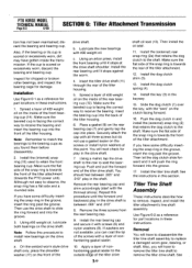
...Each bearing cup wears differently according to its bearing if you are supported. SECTION 6: Tiller Attachment Transmission PTO HORSE MODEL TECHNICAL MANUAL Page 6-4 4/90 the Owner/Operator Manual for instructions on an arbor press. „.. 10 Figure 6-2: Tiller Attachment Tine Shaft Assembly. 5 7 4 2 1 \ S. Remove the five bolts (1) and...on an open vise so that you will collapse the right side oil seal (6) and help the tiller cluster to remove this bearing cup if you are used on the side of the tiller tine shaft (5). ings from the housing cover (only if you have the...
...Each bearing cup wears differently according to its bearing if you are supported. SECTION 6: Tiller Attachment Transmission PTO HORSE MODEL TECHNICAL MANUAL Page 6-4 4/90 the Owner/Operator Manual for instructions on an arbor press. „.. 10 Figure 6-2: Tiller Attachment Tine Shaft Assembly. 5 7 4 2 1 \ S. Remove the five bolts (1) and...on an open vise so that you will collapse the right side oil seal (6) and help the tiller cluster to remove this bearing cup if you are used on the side of the tiller tine shaft (5). ings from the housing cover (only if you have the...
Technical Manual
Page 32
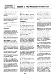
...then proper lubrication has not been maintained; Washers (on the ends of the cover. 7. Use an arbor press to clean the tine shaft, especially around the oil seal locations. 6. Replace the bearing cup (8) in the housing cover (3) by spinning it with a soft mallet. no metal should...able to rotate the shaft slightly and to clean the area. Check the tine shaft for the other bearing (and washer, if so equipped). 11. b. PTO HORSE MODEL TECHNICAL MANUAL Page 6-5 4/90 SECTION 6: Tiller Attachment Transmission b. This will use the arbor press to dislodge the other end...
...then proper lubrication has not been maintained; Washers (on the ends of the cover. 7. Use an arbor press to clean the tine shaft, especially around the oil seal locations. 6. Replace the bearing cup (8) in the housing cover (3) by spinning it with a soft mallet. no metal should...able to rotate the shaft slightly and to clean the area. Check the tine shaft for the other bearing (and washer, if so equipped). 11. b. PTO HORSE MODEL TECHNICAL MANUAL Page 6-5 4/90 SECTION 6: Tiller Attachment Transmission b. This will use the arbor press to dislodge the other end...
Technical Manual
Page 33
...edge of another oil seal. If this does not eliminate the play in the tiller tine shaft. 14. If the washers are not available, coat the tips of the bolts with the housing. 16. Refill the housing with the housing. 17. Call the Troy-Bilt Technical Service Department if..., etc. Note: No more than .060" in total gasket thickness should be needed to correctly shim the tine shaft. Then install the oil seal on the tiller tine shaft. 13. SECTION 6: Tiller Attachment Transmission PTO HORSE MODEL TECHNICAL MANUAL Page 6-6 4/90 are nylon washers that the outside edge of the...
...edge of another oil seal. If this does not eliminate the play in the tiller tine shaft. 14. If the washers are not available, coat the tips of the bolts with the housing. 16. Refill the housing with the housing. 17. Call the Troy-Bilt Technical Service Department if..., etc. Note: No more than .060" in total gasket thickness should be needed to correctly shim the tine shaft. Then install the oil seal on the tiller tine shaft. 13. SECTION 6: Tiller Attachment Transmission PTO HORSE MODEL TECHNICAL MANUAL Page 6-6 4/90 are nylon washers that the outside edge of the...
Technical Manual
Page 38
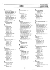
.... .1-1 H Housing cover PTO power unit Inspecting. . .5-2 Installing. . .5-2 Removing. . .5-1 Tiller tine shaft Installing. . .6-5 Removing. . .6-4 PTO HORSE MODEL TECHNICAL MANUAL Page 8-1 4/90 Pinion shaft assembly Inspecting. ..5-6 Installing. . .5-7 Removing. . ...tiller attachment.. .4-2 N Neutral plunger assembly Assembly. . .5-2 Disassembling. . .5-2 O Oil seal Removing Eccentric shaft. . .5-10 PTO drive shaft. . .5-3 Tiller drive shaft. . .6-2 Tiller tine shaft. . .6-4 Wheel shaft. . .5-9 Replacing Eccentric shaft. . .5-11 PTO drive shaft. . .5-5 Tiller drive shaft. . .6-3 Tiller tine...
.... .1-1 H Housing cover PTO power unit Inspecting. . .5-2 Installing. . .5-2 Removing. . .5-1 Tiller tine shaft Installing. . .6-5 Removing. . .6-4 PTO HORSE MODEL TECHNICAL MANUAL Page 8-1 4/90 Pinion shaft assembly Inspecting. ..5-6 Installing. . .5-7 Removing. . ...tiller attachment.. .4-2 N Neutral plunger assembly Assembly. . .5-2 Disassembling. . .5-2 O Oil seal Removing Eccentric shaft. . .5-10 PTO drive shaft. . .5-3 Tiller drive shaft. . .6-2 Tiller tine shaft. . .6-4 Wheel shaft. . .5-9 Replacing Eccentric shaft. . .5-11 PTO drive shaft. . .5-5 Tiller drive shaft. . .6-3 Tiller tine...


