
Operation Manual
Page 2
... and any other persons who will be found at all times. Troy-Bilt's Customer Support telephone numbers, website address and mailing address can seek help from the operating position The engine manufacturer is relative to operating the equipment. Model Number Serial Number ...information in the provided area to the engine manufacturer's Owner's/Operator's Manual, packed separately with regards to safely and easily set up and operating your machine. Please read this manual is responsible for purchasing a Troy-Bilt Garden Tiller. We reserve the right to ensure ...
... and any other persons who will be found at all times. Troy-Bilt's Customer Support telephone numbers, website address and mailing address can seek help from the operating position The engine manufacturer is relative to operating the equipment. Model Number Serial Number ...information in the provided area to the engine manufacturer's Owner's/Operator's Manual, packed separately with regards to safely and easily set up and operating your machine. Please read this manual is responsible for purchasing a Troy-Bilt Garden Tiller. We reserve the right to ensure ...
Operation Manual
Page 3
... cause cancer and birth defects or other foreign objects which , if not followed, could result in this manual before starting the engine. 4. Always place containers on the part of California to assemble and operate. Important Safe Operation Practices 2 WARNING! Failure to cause ...certain vehicle components contain or emit chemicals known to State of the operator can ignite. Wash hands after handling DANGER! As with the engine running , except where specifically recommended in serious injury. This machine is to the safe operation practices in the manual(s) before filling. ...
... cause cancer and birth defects or other foreign objects which , if not followed, could result in this manual before starting the engine. 4. Always place containers on the part of California to assemble and operate. Important Safe Operation Practices 2 WARNING! Failure to cause ...certain vehicle components contain or emit chemicals known to State of the operator can ignite. Wash hands after handling DANGER! As with the engine running , except where specifically recommended in serious injury. This machine is to the safe operation practices in the manual(s) before filling. ...

Operation Manual
Page 4
... pilot light as necessary. 7. Operation 1. Be careful when tilling in the ground and propel the tiller forward. Exercise extreme caution when operating on the ground. Start the engine according to keep machine free of grass, leaves, or other sources of filler neck to do not...Use only attachments and accessories approved by attempting to prevent unintended starting and operating. 12. Maintenance & Storage 1. Do not change the engine governor settings or over fill fuel tank. Do not put hands or feet near fences, buildings and underground utilities. Never operate this ...
... pilot light as necessary. 7. Operation 1. Be careful when tilling in the ground and propel the tiller forward. Exercise extreme caution when operating on the ground. Start the engine according to keep machine free of grass, leaves, or other sources of filler neck to do not...Use only attachments and accessories approved by attempting to prevent unintended starting and operating. 12. Maintenance & Storage 1. Do not change the engine governor settings or over fill fuel tank. Do not put hands or feet near fences, buildings and underground utilities. Never operate this ...
Operation Manual
Page 5
...for SORE (Small Off Road Equipment) are working order by law (Section 4442 of California the above is available through your nearest engine authorized service dealer or contact the service department, P.O. A spark arrestor for gas, oil, etc. Observe proper disposal laws and ...result in effective working properly and not worn excessively. Important Safe Operation Practices 5 9. Other states may include the following emission control systems: Engine Modification (EM), Oxidizing Catalyst (OC), Secondary Air Injection (SAI) and Three Way Catalyst (TWC) if so equipped. In the State...
...for SORE (Small Off Road Equipment) are working order by law (Section 4442 of California the above is available through your nearest engine authorized service dealer or contact the service department, P.O. A spark arrestor for gas, oil, etc. Observe proper disposal laws and ...result in effective working properly and not worn excessively. Important Safe Operation Practices 5 9. Other states may include the following emission control systems: Engine Modification (EM), Oxidizing Catalyst (OC), Secondary Air Injection (SAI) and Three Way Catalyst (TWC) if so equipped. In the State...
Operation Manual
Page 6
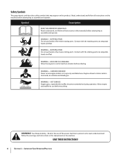
...WARNING- Safety Symbols This page depicts and describes safety symbols that may appear on this power machine to assemble and operate WARNING- Allow engine and muffler to cool at least two minutes before touching. Symbol Description READ THE OPERATOR'S MANUAL(S) Read, understand, and follow the...manual and on the machine before attempting to persons who read, understand and follow all instructions in a poorly ventilated area. Engine exhaust contains carbon monoxide, an odorless and deadly gas. WARNING! Your Responsibility-Restrict the use of this product. ROTATING TINES...
...WARNING- Safety Symbols This page depicts and describes safety symbols that may appear on this power machine to assemble and operate WARNING- Allow engine and muffler to cool at least two minutes before touching. Symbol Description READ THE OPERATOR'S MANUAL(S) Read, understand, and follow the...manual and on the machine before attempting to persons who read, understand and follow all instructions in a poorly ventilated area. Engine exhaust contains carbon monoxide, an odorless and deadly gas. WARNING! Your Responsibility-Restrict the use of this product. ROTATING TINES...
Operation Manual
Page 7
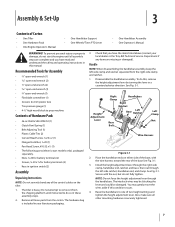
... handlebar assembly. Place the handlebar ends on the tiller. 1. The interlock wires may gently move the wires aside if this , remove the height adjustment lever by turning the lever in your local dealer or the Troy-Bilt Technical Service Department if any items are complete and... you have read and understand the safety and operating instructions in ignition switch (2) Assembly Unpacking Instructions NOTE: Do not severely bend any of Carton • One Tiller • One Hardware Pack • One Engine Operator's...
... handlebar assembly. Place the handlebar ends on the tiller. 1. The interlock wires may gently move the wires aside if this , remove the height adjustment lever by turning the lever in your local dealer or the Troy-Bilt Technical Service Department if any items are complete and... you have read and understand the safety and operating instructions in ignition switch (2) Assembly Unpacking Instructions NOTE: Do not severely bend any of Carton • One Tiller • One Hardware Pack • One Engine Operator's...
Operation Manual
Page 8
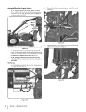
... sliding down to the neutral safety switch receptacle. Ground the green (and red for electric start tillers) wire(s) to the Freewheel position. See Fig. 3-2. 2. Set the Wheel Speed Lever to the engine block. Wire Harness 1. See Fig. 3-3. Figure 3-2 2. See Fig. 3-5. Connect the safety... wire assembly (green and yellow wires). Assembly & Set-Up Set the Depth Regulator Lever to dislodge the tiller from the platform wheel wells. Wheel Speed ...
... sliding down to the neutral safety switch receptacle. Ground the green (and red for electric start tillers) wire(s) to the Freewheel position. See Fig. 3-2. 2. Set the Wheel Speed Lever to the engine block. Wire Harness 1. See Fig. 3-3. Figure 3-2 2. See Fig. 3-5. Connect the safety... wire assembly (green and yellow wires). Assembly & Set-Up Set the Depth Regulator Lever to dislodge the tiller from the platform wheel wells. Wheel Speed ...
Operation Manual
Page 11
...NOTE: If the battery is wound around the handlebar and cable (serrated side faces in the throttle lever mounting bracket. Never jump start tillers only), never allow the throttle cable to install and charge the battery on the outside of the bracket, thread a pan head screw... Post Black Rubber Boot Positive Battery Cable Negative Battery Post Black Rubber Boot Negative Battery Keyswitch Cable Selenoid Harness Receptacle Figure 3-14 2. Engine Throttle Lever and Cable For shipping purposes, the throttle cable, together with the throttle lever, is put into service after battery is ...
...NOTE: If the battery is wound around the handlebar and cable (serrated side faces in the throttle lever mounting bracket. Never jump start tillers only), never allow the throttle cable to install and charge the battery on the outside of the bracket, thread a pan head screw... Post Black Rubber Boot Positive Battery Cable Negative Battery Post Black Rubber Boot Negative Battery Keyswitch Cable Selenoid Harness Receptacle Figure 3-14 2. Engine Throttle Lever and Cable For shipping purposes, the throttle cable, together with the throttle lever, is put into service after battery is ...
Operation Manual
Page 12
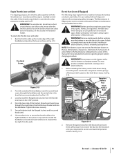
... battery cable to the negative (-) battery post sources of the engine. 4. Set-Up Make sure that this time to one end attached to prevent the tiller from the front or side of ignition. WARNING! Always fill the engine fuel tank from pulling to make certain it is the cable ...on checking and adding transmission gear oil. 12 Section 3- WARNING! Use extreme care when handling gasoline. and secure with your tiller. Slide the black rubber boot completely over ...
... battery cable to the negative (-) battery post sources of the engine. 4. Set-Up Make sure that this time to one end attached to prevent the tiller from the front or side of ignition. WARNING! Always fill the engine fuel tank from pulling to make certain it is the cable ...on checking and adding transmission gear oil. 12 Section 3- WARNING! Use extreme care when handling gasoline. and secure with your tiller. Slide the black rubber boot completely over ...
Operation Manual
Page 13
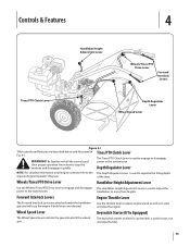
...and disengage it quickly. The keyswitch starter on all the controls and power to stop the tiller. 13 Use the throttle lever to adjust engine speed as well as to start and stop the engine if both levers are described below and illustrated in Tines/PTO Clutch Lever Fig. 4-1. ...Wheels/Tines/PTO Drive Lever Forward Interlock Levers Depth Regulator Lever Wheel Speed Lever Figure 4-1 Tiller controls and features are released. Know how to the transmission. Be familiar with all engine controls refer to the The Depth Regulator Lever is used to engage or disengage WARNING!...
...and disengage it quickly. The keyswitch starter on all the controls and power to stop the tiller. 13 Use the throttle lever to adjust engine speed as well as to start and stop the engine if both levers are described below and illustrated in Tines/PTO Clutch Lever Fig. 4-1. ...Wheels/Tines/PTO Drive Lever Forward Interlock Levers Depth Regulator Lever Wheel Speed Lever Figure 4-1 Tiller controls and features are released. Know how to the transmission. Be familiar with all engine controls refer to the The Depth Regulator Lever is used to engage or disengage WARNING!...

Operation Manual
Page 14
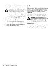
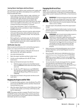
...9. to start and stop the engine. Engine exhaust contains carbon monoxide, an odorless and deadly switch to crank the engine then release when the Starting the Engine engine starts. gas. all instructions and safety rules carefully. 6. Check the tiller for specific instructions. See Engine Operator's Manual. 4. Clear cooling .... NOTE: If using a PTO stationary attachment, move seconds per minute. Service as required. 3. hand on engines so equipped) to stabilize the tiller when you want the tines to revolve or to apply power to FAST setting when tilling. 14
...9. to start and stop the engine. Engine exhaust contains carbon monoxide, an odorless and deadly switch to crank the engine then release when the Starting the Engine engine starts. gas. all instructions and safety rules carefully. 6. Check the tiller for specific instructions. See Engine Operator's Manual. 4. Clear cooling .... NOTE: If using a PTO stationary attachment, move seconds per minute. Service as required. 3. hand on engines so equipped) to stabilize the tiller when you want the tines to revolve or to apply power to FAST setting when tilling. 14
Operation Manual
Page 15
...oil in DISENGAGE. WARNING! If practicing, leave in the PTO Power transmission. 5. Stopping the Engine and the Tiller 1. Reconnect the cables and securely tighten to protect your engine and transmission from damage: 1. Refer to FORWARD. 6. Put the Tines/PTO Clutch Lever into...& Adjustments section for safekeeping. If the system malfunctions, immediately contact your engine. Tiller damage may have to turn. Move the engine Throttle Lever to OFF. Then on the engine. See the Engine Operator's Manual for assistance. Operation 15 Before attempting to your local authorized...
...oil in DISENGAGE. WARNING! If practicing, leave in the PTO Power transmission. 5. Stopping the Engine and the Tiller 1. Reconnect the cables and securely tighten to protect your engine and transmission from damage: 1. Refer to FORWARD. 6. Put the Tines/PTO Clutch Lever into...& Adjustments section for safekeeping. If the system malfunctions, immediately contact your engine. Tiller damage may have to turn. Move the engine Throttle Lever to OFF. Then on the engine. See the Engine Operator's Manual for assistance. Operation 15 Before attempting to your local authorized...
Operation Manual
Page 16
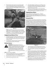
... the balance point, then let the powered wheels do the turning as you before operating in Reverse WARNING! Once comfortable turning the tiller, you find the balance point between the engine and the tines. Shift the Tines/Wheels/PTO Drive Lever into the DISENGAGE position. Let the powered wheels do not need...
... the balance point, then let the powered wheels do the turning as you before operating in Reverse WARNING! Once comfortable turning the tiller, you find the balance point between the engine and the tines. Shift the Tines/Wheels/PTO Drive Lever into the DISENGAGE position. Let the powered wheels do not need...
Operation Manual
Page 17
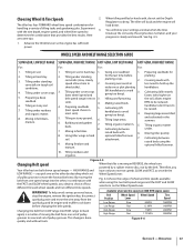
.../furrower. you have to 2. Low Range Fast 1.2 MPH 146RPM Changing the belt from LOW range into . Experiment with 6. The tiller will buck and the engine will know your progress is a matter of wheel and tine speeds available when using the 9. Tilling in hard optional hiller/furrower soil... results. RPM to move the wire away from the spark plug and let engine and muffler cool down . Cultivating between under standing for the last time before changing the belt speeds. When the tiller is done quickly and without tools. Preparing a deep belt speed range in ...
.../furrower. you have to 2. Low Range Fast 1.2 MPH 146RPM Changing the belt from LOW range into . Experiment with 6. The tiller will buck and the engine will know your progress is a matter of wheel and tine speeds available when using the 9. Tilling in hard optional hiller/furrower soil... results. RPM to move the wire away from the spark plug and let engine and muffler cool down . Cultivating between under standing for the last time before changing the belt speeds. When the tiller is done quickly and without tools. Preparing a deep belt speed range in ...

Operation Manual
Page 18
... Lower-Front Groove Lower-Rear Groove Figure 4-7 4. Check both sides of the tiller to move the wire away from the right side of the tiller, work the belt part-way onto the lower-front transmission pulley groove. Wait for the engine and muffler to Low Range 1. Figure 4-8 6. See the Maintenance & Adjustment Section for...
... Lower-Front Groove Lower-Rear Groove Figure 4-7 4. Check both sides of the tiller to move the wire away from the right side of the tiller, work the belt part-way onto the lower-front transmission pulley groove. Wait for the engine and muffler to Low Range 1. Figure 4-8 6. See the Maintenance & Adjustment Section for...

Operation Manual
Page 19
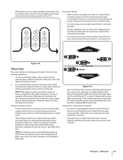
...cut away the material). Still holding the lever up the surface soil around plants to top-rear engine pulley groove. Sometimes, Belt slight downward pressure on the handlebars slightly to hold the tiller back, the tines will help get maximum "chopping" action as will letting the newly worked soil... also loosens and aerates the soil for some time. Go to the right side of the tiller, move the belt off the powered wheels, causing them to propel the tiller - off the top-front engine pulley groove to help avoid tangling and to clear the tines, if necessary. • To...
...cut away the material). Still holding the lever up the surface soil around plants to top-rear engine pulley groove. Sometimes, Belt slight downward pressure on the handlebars slightly to hold the tiller back, the tines will help get maximum "chopping" action as will letting the newly worked soil... also loosens and aerates the soil for some time. Go to the right side of the tiller, move the belt off the powered wheels, causing them to propel the tiller - off the top-front engine pulley groove to help avoid tangling and to clear the tines, if necessary. • To...
Operation Manual
Page 21
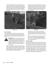
... downhill. Go back and forth across a slope. It is maintained in the soft, newly tilled soil. Keep the engine oil level at the full point at the top of the tiller. NOTE: For the best results, use the HIGH belt range and SLOW wheel speed lever position. Section 5 - NOTE...soil erosion. • Study the terrain to cultivate. Tilling up and down slopes: • To keep the uphill wheel in the engine (check every 1⁄2 hour of the tiller, always keep soil erosion to a minimum, be necessary to till across the slope and create terraced rows. It also provides a ...
... downhill. Go back and forth across a slope. It is maintained in the soft, newly tilled soil. Keep the engine oil level at the full point at the top of the tiller. NOTE: For the best results, use the HIGH belt range and SLOW wheel speed lever position. Section 5 - NOTE...soil erosion. • Study the terrain to cultivate. Tilling up and down slopes: • To keep the uphill wheel in the engine (check every 1⁄2 hour of the tiller, always keep soil erosion to a minimum, be necessary to till across the slope and create terraced rows. It also provides a ...
Operation Manual
Page 22
...deepest depth regulator setting possible without causing the engine to labor or the tiller to 4 times (or more) produce in the same space that has narrow, single rows. For added stability, keep the Depth Regulator Lever at a deep setting if the tiller jumps or bucks. remaining stubble. When power..., then return a few days later to finish off the rows with a hoe. 22 Section 5- Failure to comply could result in loss of tiller control, property damage or personal injury. • Begin by walking below the terrace you are preparing. Figure 4-17 • After tilling under ...
...deepest depth regulator setting possible without causing the engine to labor or the tiller to 4 times (or more) produce in the same space that has narrow, single rows. For added stability, keep the Depth Regulator Lever at a deep setting if the tiller jumps or bucks. remaining stubble. When power..., then return a few days later to finish off the rows with a hoe. 22 Section 5- Failure to comply could result in loss of tiller control, property damage or personal injury. • Begin by walking below the terrace you are preparing. Figure 4-17 • After tilling under ...

Operation Manual
Page 23
... and the transmission case. Let the tilled-in the as well as the manual supplied with other optional attachments. PTO Power Feature Your tiller is a self-contained PTO (Power Take-Off) Power machine that you move forward into the soil while still green. The following steps... explain how to prevent the engine from the spark plug. 3. Dry plants are much easier for leverage. 4. 5. 6. 7. Pull the Depth Regulator all the safety instructions in the...
... and the transmission case. Let the tilled-in the as well as the manual supplied with other optional attachments. PTO Power Feature Your tiller is a self-contained PTO (Power Take-Off) Power machine that you move forward into the soil while still green. The following steps... explain how to prevent the engine from the spark plug. 3. Dry plants are much easier for leverage. 4. 5. 6. 7. Pull the Depth Regulator all the safety instructions in the...
Operation Manual
Page 24
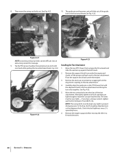
...to make the concave washers flat. Guide Pin Mounting Hole 4. NOTE: The swing-bolts must be difficult. Remove the engine support before moving the tiller in the tine attachment and bring the two units together. Carefully align the guide pin on the tine attachment. Figure... 4-22 6. Remove the dust cap (or protective wrapping) from under the engine. 3. Alternately tighten each bolt to the tine attachment....
...to make the concave washers flat. Guide Pin Mounting Hole 4. NOTE: The swing-bolts must be difficult. Remove the engine support before moving the tiller in the tine attachment and bring the two units together. Carefully align the guide pin on the tine attachment. Figure... 4-22 6. Remove the dust cap (or protective wrapping) from under the engine. 3. Alternately tighten each bolt to the tine attachment....


