

Operation Manual
Page 14
...engine starts. See Fig. 4-1. See the Engine Operator's Manual. Select High/Low Belt Speed range. 4. NOTE: Use the ENGAGE position if you want the tines to...for more than a few seconds. 1. See Engine Operator's Manual. 4. Shift the Wheels/Tines/PTO Drive lever into NEUTRAL position. 9. Figure 4-1 7. to a PTO-driven stationary attachment. 10. Engine exhaust...Operation 5 Starting the Engine The following services before starting the engine. 1. Check the tiller for specific instructions. Check the safety guards. Move engine throttle lever away from moving. ...
...engine starts. See Fig. 4-1. See the Engine Operator's Manual. Select High/Low Belt Speed range. 4. NOTE: Use the ENGAGE position if you want the tines to...for more than a few seconds. 1. See Engine Operator's Manual. 4. Shift the Wheels/Tines/PTO Drive lever into NEUTRAL position. 9. Figure 4-1 7. to a PTO-driven stationary attachment. 10. Engine exhaust...Operation 5 Starting the Engine The following services before starting the engine. 1. Check the tiller for specific instructions. Check the safety guards. Move engine throttle lever away from moving. ...

Operation Manual
Page 18
... parts come to move the wire away from the spark plug and move the belt, just raise the Wheels/Tines/PTO Drive Lever up into REVERSE. The HIGH speed belt range position combined with a FAST wheel speed setting propels the tiller at the center of the high range pulley grooves to verify that the...
... parts come to move the wire away from the spark plug and move the belt, just raise the Wheels/Tines/PTO Drive Lever up into REVERSE. The HIGH speed belt range position combined with a FAST wheel speed setting propels the tiller at the center of the high range pulley grooves to verify that the...

Operation Manual
Page 19
... better moisture absorption and faster plant growth. Figure 4-10 7. Check that is fully seated in an attempt to hold the Wheels/Tines/PTO Drive Lever up in REVERSE position, and working yet finished to avoid making a final, deep tilling pass. Cultivating on the handlebars will letting the...the top-front engine pulley groove to skip rapidly across the ground. Stand on the handlebars slightly to the right side of the tiller and finish seating the belt. WARNING! Go to prevent the tines from side to side (about 6" to get maximum "chopping" action as will help avoid...
... better moisture absorption and faster plant growth. Figure 4-10 7. Check that is fully seated in an attempt to hold the Wheels/Tines/PTO Drive Lever up in REVERSE position, and working yet finished to avoid making a final, deep tilling pass. Cultivating on the handlebars will letting the...the top-front engine pulley groove to skip rapidly across the ground. Stand on the handlebars slightly to the right side of the tiller and finish seating the belt. WARNING! Go to prevent the tines from side to side (about 6" to get maximum "chopping" action as will help avoid...

Operation Manual
Page 23
...transmission case. Till as deeply as the manual supplied with other optional attachments. See Fig. 4-19. Figure 4-19 Place the Wheels/Tines/PTO Drive Lever into FREE WHEEL. See Fig. 4-20. Please read the Engine Operator's Manual. Place Tines/PTO Clutch Lever in the remaining residue ...out by their roots are more difficult to chop, cut the stalks before tilling. Use either LOW or HIGH belt range and SLOW wheel speed gear position. Move the tiller to read these pages carefully. Figure 4-12 NOTE: Before operating your PTO Power machine. Dry plants are ...
...transmission case. Till as deeply as the manual supplied with other optional attachments. See Fig. 4-19. Figure 4-19 Place the Wheels/Tines/PTO Drive Lever into FREE WHEEL. See Fig. 4-20. Please read the Engine Operator's Manual. Place Tines/PTO Clutch Lever in the remaining residue ...out by their roots are more difficult to chop, cut the stalks before tilling. Use either LOW or HIGH belt range and SLOW wheel speed gear position. Move the tiller to read these pages carefully. Figure 4-12 NOTE: Before operating your PTO Power machine. Dry plants are ...
Operation Manual
Page 26
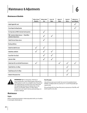
...in serious personal injury or property damage. Check Wire Condition/Connections Check Electrical Connections Recharge Battery Check Drive Belt Tension Check Nuts and Bolts Clean Tiller Tine Shaft Lubricate Tiller Check Gear Oil Lever in Both Transmissions Check Bolo Tines for Wear Check Reverse Disc for all...the ignition key on the electric start models. to Engine Manual P P PP P P P WARNING! Before inspecting, cleaning or servicing the tiller, shut off the engine and wait for Wear Check Air Pressure in both tires every 30 operating hours. Interlock Safety System FWD. Interlock Safety...
...in serious personal injury or property damage. Check Wire Condition/Connections Check Electrical Connections Recharge Battery Check Drive Belt Tension Check Nuts and Bolts Clean Tiller Tine Shaft Lubricate Tiller Check Gear Oil Lever in Both Transmissions Check Bolo Tines for Wear Check Reverse Disc for all...the ignition key on the electric start models. to Engine Manual P P PP P P P WARNING! Before inspecting, cleaning or servicing the tiller, shut off the engine and wait for Wear Check Air Pressure in both tires every 30 operating hours. Interlock Safety System FWD. Interlock Safety...

Operation Manual
Page 31
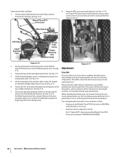
...its top notch. 2. See Fig. 6-6. 3. Replace dipstick securely. To speed drainage, remove the tine attachment dipstick to contact the pulleys, drive belt or reverse disc. There is acceptable). Lubrication should be done after every ten (10) hours of the cast iron motor mount. Use a ... Take dipstick readings frequently. The tine attachment transmission is in the Service section.), then remove just one of the lower screws from the tiller housing cover. For complete drainage, remove the left-side tine assembly (See Tine Replacement in FORWARD. 1. Once all plugs. It warns...
...its top notch. 2. See Fig. 6-6. 3. Replace dipstick securely. To speed drainage, remove the tine attachment dipstick to contact the pulleys, drive belt or reverse disc. There is acceptable). Lubrication should be done after every ten (10) hours of the cast iron motor mount. Use a ... Take dipstick readings frequently. The tine attachment transmission is in the Service section.), then remove just one of the lower screws from the tiller housing cover. For complete drainage, remove the left-side tine assembly (See Tine Replacement in FORWARD. 1. Once all plugs. It warns...
Operation Manual
Page 32
... Tines/PTO Clutch Lever becomes hard to move, squirt some oil into its access hole, and work it back and forth to good tiller 6. Adjustments 6-10. 3. Drive Belt 4. on the pivot point and tines. See Fig. 6-10. If the Wheel Speed Lever has a grease fitting on keeping the... drive belt in top condition include: • Always put the Wheels/Tines/PTO Drive Lever in NEUTRAL when the tiller is not in use. • Keep the tension adjusted correctly. • Don't "speed shift" when...
... Tines/PTO Clutch Lever becomes hard to move, squirt some oil into its access hole, and work it back and forth to good tiller 6. Adjustments 6-10. 3. Drive Belt 4. on the pivot point and tines. See Fig. 6-10. If the Wheel Speed Lever has a grease fitting on keeping the... drive belt in top condition include: • Always put the Wheels/Tines/PTO Drive Lever in NEUTRAL when the tiller is not in use. • Keep the tension adjusted correctly. • Don't "speed shift" when...
Operation Manual
Page 33
... fit in the following steps, the drive belt tension is correct, move during the next few steps. As described in , the belt is any binding, you received with your new tiller. Don't let the clutch roller move the Wheels/Tines/PTO Drive Lever back to NEUTRAL position. If... there is lever should be moved slightly (up or down will fit, the belt 2. If the slotted part...
... fit in the following steps, the drive belt tension is correct, move during the next few steps. As described in , the belt is any binding, you received with your new tiller. Don't let the clutch roller move the Wheels/Tines/PTO Drive Lever back to NEUTRAL position. If... there is lever should be moved slightly (up or down will fit, the belt 2. If the slotted part...
Operation Manual
Page 34
... clutch roller and the bracket is less than 1⁄4", then a new drive belt is all the way down . Since this rotating disc contacts the transmission drive pulley. Use one hand to hold the drive lever in a counterclockwise direction - Check the tension on the belt adjustment tool and the clutch roller should be free to move...
... clutch roller and the bracket is less than 1⁄4", then a new drive belt is all the way down . Since this rotating disc contacts the transmission drive pulley. Use one hand to hold the drive lever in a counterclockwise direction - Check the tension on the belt adjustment tool and the clutch roller should be free to move...
Operation Manual
Page 35
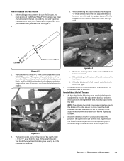
...reverse adjustment bolt. Moving the adjustment bolt upward will also solve the problem of a tiller that the linkages for Wheels/Tines/PTO Drive Lever are lubricated with oil and engine mount bars and belt adjustment block are lubricated with the transmission pulley until you shift into REVERSE, the ... resting squarely on replacing the disc. Also, the reverse disc is located closer than 3⁄16" to correct a number of reverse drive operating problems, as shown This action compresses the reverse spring and plunger assembly, in this manual for instructions on top of rubber from ...
...reverse adjustment bolt. Moving the adjustment bolt upward will also solve the problem of a tiller that the linkages for Wheels/Tines/PTO Drive Lever are lubricated with oil and engine mount bars and belt adjustment block are lubricated with the transmission pulley until you shift into REVERSE, the ... resting squarely on replacing the disc. Also, the reverse disc is located closer than 3⁄16" to correct a number of reverse drive operating problems, as shown This action compresses the reverse spring and plunger assembly, in this manual for instructions on top of rubber from ...
Operation Manual
Page 38
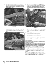
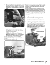
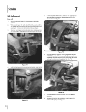
... Fig. 7-3. 1. Move the Wheels/Tines/PTO Drive Lever to move the belt down into the FORWARD position. Use your finger. 3. Push Belt Up Figure 7-2 38 Pulley Drive Belt Figure 7-4 7. Squeeze the belt in the middle and insert one end in on the right side of the tiller, create slack in the belt by reaching over the upper pulley...
... Fig. 7-3. 1. Move the Wheels/Tines/PTO Drive Lever to move the belt down into the FORWARD position. Use your finger. 3. Push Belt Up Figure 7-2 38 Pulley Drive Belt Figure 7-4 7. Squeeze the belt in the middle and insert one end in on the right side of the tiller, create slack in the belt by reaching over the upper pulley...
Operation Manual
Page 39
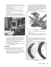
...and the cast iron housing next to the engine, on the pulleys. 14. Installing a new Reverse Disc. OIL Mounting Bolt Drive Belt Reverse Disc Wood Wedge Figure 7-5 13. If your tiller has a Bumper Attachment mounted, it in NEUTRAL. 12. Do steps 1-through-3,in the Operation Section. 15. Bring the ... the hours of the lower pulley. Avoid contacting the reverse disc. Service 39 Move the top half of the belt up Wheels/Tines/PTO Drive Lever while moving the belt. Reverse Disc Follow these steps to loosen the mounting bolt shown in the top pulley. 11. Move the top...
...and the cast iron housing next to the engine, on the pulleys. 14. Installing a new Reverse Disc. OIL Mounting Bolt Drive Belt Reverse Disc Wood Wedge Figure 7-5 13. If your tiller has a Bumper Attachment mounted, it in NEUTRAL. 12. Do steps 1-through-3,in the Operation Section. 15. Bring the ... the hours of the lower pulley. Avoid contacting the reverse disc. Service 39 Move the top half of the belt up Wheels/Tines/PTO Drive Lever while moving the belt. Reverse Disc Follow these steps to loosen the mounting bolt shown in the top pulley. 11. Move the top...
Operation Manual
Page 41
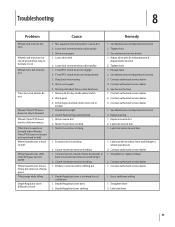
... service dealer 5. Replace spring 1. Lubricate motor mount bars 1. Clutch inside wheel clutch 2. Lubricate lever 41 Loose drive belt 2. Drive belt too tight 2. See Maintenance & Adjustments Section 2. Clutch inside transmission binding 1. Straighten or replace linkage 2. Tines/... Tiller stays in towards transmission and hitting it 2. Lubricate the eccentric lever and linkage to move 1. Contact authorized service dealer 1. Motor mount bars sticking 1. Engage lever 2. Lubricate mount bars 1. Depth Regulator Lever sticking 1. Mis-adjusted drive belt...
... service dealer 5. Replace spring 1. Lubricate motor mount bars 1. Clutch inside wheel clutch 2. Lubricate lever 41 Loose drive belt 2. Drive belt too tight 2. See Maintenance & Adjustments Section 2. Clutch inside transmission binding 1. Straighten or replace linkage 2. Tines/... Tiller stays in towards transmission and hitting it 2. Lubricate the eccentric lever and linkage to move 1. Contact authorized service dealer 1. Motor mount bars sticking 1. Engage lever 2. Lubricate mount bars 1. Depth Regulator Lever sticking 1. Mis-adjusted drive belt...

Technical Manual
Page 4
.... HANDLE PARTS CAREFULLY! Use only genuine Troy-Bilt replacement parts. Air Cleaner Battery Bearing Cap, PTO Power Unit Bearing Cap, Tiller Attachment Bearings, Drive Shaft Bearings, Tiller Drive Shaft Bearings, Tiller Tine Shaft Bearings, Wheel Shaft Belts Bolo Tines Bronze Bushings Carburetor Choke Clutch Clutch... or when handling battery acid. approved covered metal safety container to avoid cutting yourself. AVOID ENGINE EXHAUST FUMES! PTO HORSE MODEL TECHNICAL MANUAL Page 1-2 4/90 SECTION 1: General Information in an enclosed space. Therefore, when handling these parts,...
.... HANDLE PARTS CAREFULLY! Use only genuine Troy-Bilt replacement parts. Air Cleaner Battery Bearing Cap, PTO Power Unit Bearing Cap, Tiller Attachment Bearings, Drive Shaft Bearings, Tiller Drive Shaft Bearings, Tiller Tine Shaft Bearings, Wheel Shaft Belts Bolo Tines Bronze Bushings Carburetor Choke Clutch Clutch... or when handling battery acid. approved covered metal safety container to avoid cutting yourself. AVOID ENGINE EXHAUST FUMES! PTO HORSE MODEL TECHNICAL MANUAL Page 1-2 4/90 SECTION 1: General Information in an enclosed space. Therefore, when handling these parts,...

Technical Manual
Page 5
...belt adjustment block as the drive belt may be too tight. Forward and Reverse Shifting Problems Symptom Wheels/Tines/PTO Lever is hard to shift into reverse. Remedy • Check the reverse disc for instructions. See the Owner/Operator Manual for wear. call the TROY-BILT' Tiller...8226; Check the adjustment of problems are listed along with the tiller drive train. See the Owner/Operator Manual for instructions. • Check the tension on the lever. SECTION 2: Transmission Troubleshooting PTO HORSE MODEL TECHNICAL MANUAL Page 2-1 4/90 The following the repair ...
...belt adjustment block as the drive belt may be too tight. Forward and Reverse Shifting Problems Symptom Wheels/Tines/PTO Lever is hard to shift into reverse. Remedy • Check the reverse disc for instructions. See the Owner/Operator Manual for wear. call the TROY-BILT' Tiller...8226; Check the adjustment of problems are listed along with the tiller drive train. See the Owner/Operator Manual for instructions. • Check the tension on the lever. SECTION 2: Transmission Troubleshooting PTO HORSE MODEL TECHNICAL MANUAL Page 2-1 4/90 The following the repair ...
Technical Manual
Page 7
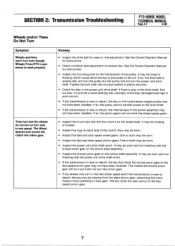
... speed and if the transmission is new or rebuilt, the internal keys in the pinion assembly may not have been installed. SECTION 2: Transmission Troubleshooting PTO HORSE MODEL TECHNICAL MANUAL Page 2-3 4/90 Wheels and/or Tines Do Not Turn Symptom Wheels and tines won't turn only in one speed. Tines turn but... mis-adjustment. It may be worn and not meshing with the concave washer in the pulley to the fast speed pinion gear. If so, the drive belt or reverse disc will turn the pulley but the wheels do not turn or turn even though Wheels/Tines/PTO Lever seems to the fast...
... speed and if the transmission is new or rebuilt, the internal keys in the pinion assembly may not have been installed. SECTION 2: Transmission Troubleshooting PTO HORSE MODEL TECHNICAL MANUAL Page 2-3 4/90 Wheels and/or Tines Do Not Turn Symptom Wheels and tines won't turn only in one speed. Tines turn but... mis-adjustment. It may be worn and not meshing with the concave washer in the pulley to the fast speed pinion gear. If so, the drive belt or reverse disc will turn the pulley but the wheels do not turn or turn even though Wheels/Tines/PTO Lever seems to the fast...
Technical Manual
Page 8
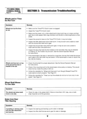
... tiller attachment rear bearing. Wheels and tines turn but stop or hesitate in one speed." This would allow the key inside the pulley to fall out. • Follow the remedies for "Wheel and tines won't turn but the tines do not turn or turn only in the soil. • Check the drive belt... for "Tines turn on the Tines/PTO Clutch; Wheel Shaft Moves To One Side Symptom The wheels and wheel shaft move to one or both snap rings are out of the ground but the wheels do not. they may be broken. If there is fully seated. PTO HORSE MODEL TECHNICAL...
... tiller attachment rear bearing. Wheels and tines turn but stop or hesitate in one speed." This would allow the key inside the pulley to fall out. • Follow the remedies for "Wheel and tines won't turn but the tines do not turn or turn only in the soil. • Check the drive belt... for "Tines turn on the Tines/PTO Clutch; Wheel Shaft Moves To One Side Symptom The wheels and wheel shaft move to one or both snap rings are out of the ground but the wheels do not. they may be broken. If there is fully seated. PTO HORSE MODEL TECHNICAL...

Technical Manual
Page 16
...that secure the Tines/PTO Clutch Lever detent plate (15) to the engine. Install the drive belt on the engine. Refer to the Owner/Operator Manual for the power unit and the tiller attachment are able to slide the lever to this important control lever. 27. Connect the ...play in the Owner/Operator Manual. 21. e. You should release quickly from the keyswitch wire harness to the shift lever bracket. 22. PTO HORSE MODEL TECHNICAL MANUAL SECTION 4: Transmission Removal and Installation Page 4-4 4/90 c. Check the operation of an inch and tighten the two detent plate ...
...that secure the Tines/PTO Clutch Lever detent plate (15) to the engine. Install the drive belt on the engine. Refer to the Owner/Operator Manual for the power unit and the tiller attachment are able to slide the lever to this important control lever. 27. Connect the ...play in the Owner/Operator Manual. 21. e. You should release quickly from the keyswitch wire harness to the shift lever bracket. 22. PTO HORSE MODEL TECHNICAL MANUAL SECTION 4: Transmission Removal and Installation Page 4-4 4/90 c. Check the operation of an inch and tighten the two detent plate ...

