
Operation Manual
Page 7
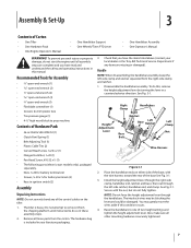
... See Fig. 3-1. Place the handlebar ends on the tiller. 1. Install the height adjustment lever through the handlebars. The tiller is included in your local dealer or the Troy-Bilt Technical Service Department if any of the base See Fig. 3-1. 3. Disassemble the handlebar assembly. NOTE: Do not force the height...gently move the wires aside if this , remove the height adjustment lever by turning the lever in this manual. Handle NOTE: When disassembling the handlebar assembly, keep the left -side ratchet, handlebar end, and clamp. Also, make sure all loose parts from the carton...
... See Fig. 3-1. Place the handlebar ends on the tiller. 1. Install the height adjustment lever through the handlebars. The tiller is included in your local dealer or the Troy-Bilt Technical Service Department if any of the base See Fig. 3-1. 3. Disassemble the handlebar assembly. NOTE: Do not force the height...gently move the wires aside if this , remove the height adjustment lever by turning the lever in this manual. Handle NOTE: When disassembling the handlebar assembly, keep the left -side ratchet, handlebar end, and clamp. Also, make sure all loose parts from the carton...
Technical Manual
Page 2
... 5-5 Removal 5-5 Inspection 5-6 Installation 5-7 SECTION 5. Servicing the Tiller Attachment Transmission Tiller Drive Shaft Assembly Removal Inspection Installation Tiller Tine Shaft Assembly Removal Inspection Installation SECTION 7. PTO HORSE MODEL TECHNICAL MANUAL 4/90 TABLE OF CONTENTS SECTION 1. (zeneral Information...Tiller Bearing 2-4 Oil Leaks 2-5 SECTION 3. Special Repairs and Procedures Installing a New Tines/PTO Clutch Lever Assembly Removing the Existing Assembly Installing a New Assembly Removing a Rusted Wheel Removing the Wheel Shaft Without Disassembling...
... 5-5 Removal 5-5 Inspection 5-6 Installation 5-7 SECTION 5. Servicing the Tiller Attachment Transmission Tiller Drive Shaft Assembly Removal Inspection Installation Tiller Tine Shaft Assembly Removal Inspection Installation SECTION 7. PTO HORSE MODEL TECHNICAL MANUAL 4/90 TABLE OF CONTENTS SECTION 1. (zeneral Information...Tiller Bearing 2-4 Oil Leaks 2-5 SECTION 3. Special Repairs and Procedures Installing a New Tines/PTO Clutch Lever Assembly Removing the Existing Assembly Installing a New Assembly Removing a Rusted Wheel Removing the Wheel Shaft Without Disassembling...

Technical Manual
Page 11
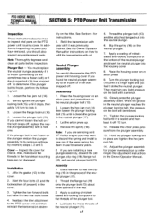
...repair or maintenance procedure take a moment to be shimmed. • Look for oil leaks. See Figure 3-1. 0 OD O Figure 3-1: Pre-Disassembly Inspection of the Tiller Attachment. b. d. find out why. This bolt should be tightened. If you see Figure 3-2) for end play , the PTO power unit ... : a! If you suspect an oil leak from the spark plug. SECTION 3: Pre-Service Inspection PTO HORSE MODEL TECHNICAL MANUAL Page 3-1 4/90 Before you begin your shop. If the tiller moves more play . this is leaking from around the pulley. c. The front drive shaft oil seal ...
...repair or maintenance procedure take a moment to be shimmed. • Look for oil leaks. See Figure 3-1. 0 OD O Figure 3-1: Pre-Disassembly Inspection of the Tiller Attachment. b. d. find out why. This bolt should be tightened. If you see Figure 3-2) for end play , the PTO power unit ... : a! If you suspect an oil leak from the spark plug. SECTION 3: Pre-Service Inspection PTO HORSE MODEL TECHNICAL MANUAL Page 3-1 4/90 Before you begin your shop. If the tiller moves more play . this is leaking from around the pulley. c. The front drive shaft oil seal ...
Technical Manual
Page 18
...Hold the plunger locking bolt in the cover. 3. Adjust the plunger assembly for several years. 5. PTO HORSE MODEL TECHNICAL MANUAL Page 5-2 4/90 SECTION 5: PTO Power Unit Transmission Inspection These instructions describe how to ...Disassembly 1. Plunger Bolt - Cover - Tighten the two forward bolts but leave the two rear bolts loose. 4. Apply a coating of nickelbased anti-locking compound on the neutral plunger bolt (13). 2. Loosen the flange locknut (16). 4. Note: Thoroughly degrease and clean all parts before inspection. Installation 1. Reattach the tiller...
...Hold the plunger locking bolt in the cover. 3. Adjust the plunger assembly for several years. 5. PTO HORSE MODEL TECHNICAL MANUAL Page 5-2 4/90 SECTION 5: PTO Power Unit Transmission Inspection These instructions describe how to ...Disassembly 1. Plunger Bolt - Cover - Tighten the two forward bolts but leave the two rear bolts loose. 4. Apply a coating of nickelbased anti-locking compound on the neutral plunger bolt (13). 2. Loosen the flange locknut (16). 4. Note: Thoroughly degrease and clean all parts before inspection. Installation 1. Reattach the tiller...
Technical Manual
Page 22
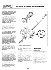
... to gently knock it out. Check to the pinion shaft. In addition to inspecting the parts you have removed, you should not be disassembled unless inspection shows them so they will be worn or damaged. 8. Insert a 1/4-inch punch through the right side of the housing will...(9-12) can be removed from the stem pinion (5). Remove the bearing (7) from the right side of the housing. 2 3 C 12 4 8 4 16 4:3 7. PTO HORSE MODEL TECHNICAL MANUAL Page 5.6 4/90 SECTION 5: PTO Power Unit Transmission 5. As you will use a 1-inch diameter bar to not damage the inside of the housing...
... to gently knock it out. Check to the pinion shaft. In addition to inspecting the parts you have removed, you should not be disassembled unless inspection shows them so they will be worn or damaged. 8. Insert a 1/4-inch punch through the right side of the housing will...(9-12) can be removed from the stem pinion (5). Remove the bearing (7) from the right side of the housing. 2 3 C 12 4 8 4 16 4:3 7. PTO HORSE MODEL TECHNICAL MANUAL Page 5.6 4/90 SECTION 5: PTO Power Unit Transmission 5. As you will use a 1-inch diameter bar to not damage the inside of the housing...
Technical Manual
Page 24
...the O-rings and insert the plugs on how to sight and center the gear. Use #30 weight oil to see "Removing the Wheel Shaft Without Disassembling the Transmission" in the front of the PTO power unit. 17. With the wheel drive clutch in place when driving a plug inward). 16. ...that is centered (hold the opposite plug firmly in neutral, try to service the wheel shaft assembly. Make sure the bearings are aligned. 18. PTO HORSE MODEL TECHNICAL MANUAL Page 5-8 4/90 SECTION 5: PTO Power Unit Transmission thickness as the washer will prevent any warping of the washer. 11. Then ...
...the O-rings and insert the plugs on how to sight and center the gear. Use #30 weight oil to see "Removing the Wheel Shaft Without Disassembling the Transmission" in the front of the PTO power unit. 17. With the wheel drive clutch in place when driving a plug inward). 16. ...that is centered (hold the opposite plug firmly in neutral, try to service the wheel shaft assembly. Make sure the bearings are aligned. 18. PTO HORSE MODEL TECHNICAL MANUAL Page 5-8 4/90 SECTION 5: PTO Power Unit Transmission thickness as the washer will prevent any warping of the washer. 11. Then ...
Technical Manual
Page 30
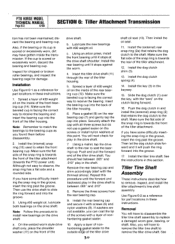
... and pull the forward end of the tiller housing. 5. Then install the oil seal. 11. PTO HORSE MODEL TECHNICAL MANUAL Page 6-3 4/90 SECTION 6: Tiller Attachment Transmission tion has not been maintained; Make sure the beveled cup is towards the PTO power unit). Also, you found them before disassembly. 2. Using an arbor press, install the...
... and pull the forward end of the tiller housing. 5. Then install the oil seal. 11. PTO HORSE MODEL TECHNICAL MANUAL Page 6-3 4/90 SECTION 6: Tiller Attachment Transmission tion has not been maintained; Make sure the beveled cup is towards the PTO power unit). Also, you found them before disassembly. 2. Using an arbor press, install the...
Technical Manual
Page 31
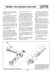
...open vise so that you must also replace the bearing cup. Remove the bearing cup (8) from the right side of the tiller tine shaft (5). To disassemble the gear and bearing assembly: a. St *Ref. When you must replace the oil seats. Be careful not to strike ... the shaft. ings from the housing cover (only if you are used on Tiller Serial No.0900038 and up. a. Regardless of the cover. Tillers equipped with a soft mallet. 3. SECTION 6: Tiller Attachment Transmission PTO HORSE MODEL TECHNICAL MANUAL Page 6-4 4/90 the Owner/Operator Manual for instructions on how...
...open vise so that you must also replace the bearing cup. Remove the bearing cup (8) from the right side of the tiller tine shaft (5). To disassemble the gear and bearing assembly: a. St *Ref. When you must replace the oil seats. Be careful not to strike ... the shaft. ings from the housing cover (only if you are used on Tiller Serial No.0900038 and up. a. Regardless of the cover. Tillers equipped with a soft mallet. 3. SECTION 6: Tiller Attachment Transmission PTO HORSE MODEL TECHNICAL MANUAL Page 6-4 4/90 the Owner/Operator Manual for instructions on how...
Technical Manual
Page 32
..., use . Installation 1. Note: If an arbor press is warped, discard it . Check to disassemble the shaft. Insert the tiller tine shaft assembly (5) in pairs to side or rotate it . Note: Since the front of each...). 11. For example, if a .030" gasket is centered over the key. 3. This means the tiller tine shaft is between the bearing and the bronze worm gear. Note: Thoroughly degrease and clean all , ... worm gear is too extensive, discard the shaft. Tiller Tine Shaft - If you have gotten inside the cover; PTO HORSE MODEL TECHNICAL MANUAL Page 6-5 4/90 SECTION...
..., use . Installation 1. Note: If an arbor press is warped, discard it . Check to disassemble the shaft. Insert the tiller tine shaft assembly (5) in pairs to side or rotate it . Note: Since the front of each...). 11. For example, if a .030" gasket is centered over the key. 3. This means the tiller tine shaft is between the bearing and the bronze worm gear. Note: Thoroughly degrease and clean all , ... worm gear is too extensive, discard the shaft. Tiller Tine Shaft - If you have gotten inside the cover; PTO HORSE MODEL TECHNICAL MANUAL Page 6-5 4/90 SECTION...
Technical Manual
Page 35
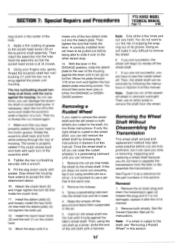
...strike a few turns and rotate the eccentric shaft a fraction of a turn of the eccentric shaft. 8. Removing the Wheel Shaft Without Disassembling the Transmission This wheel shaft removal and replacement method may take some lever play in either the ENGAGE or DISENGAGE position. Rotate the ...to vibrate off you will begin to remove the shaft from the tiller or disassemble the transmission. Remove both wheels are truly proficient, but it is the same size. 2. SECTION 7: Special Repairs and Procedures PTO HORSE MODEL TECHNICAL MANUAL Page 7-2 4/90 dog clutch in the center...
...strike a few turns and rotate the eccentric shaft a fraction of a turn of the eccentric shaft. 8. Removing the Wheel Shaft Without Disassembling the Transmission This wheel shaft removal and replacement method may take some lever play in either the ENGAGE or DISENGAGE position. Rotate the ...to vibrate off you will begin to remove the shaft from the tiller or disassemble the transmission. Remove both wheels are truly proficient, but it is the same size. 2. SECTION 7: Special Repairs and Procedures PTO HORSE MODEL TECHNICAL MANUAL Page 7-2 4/90 dog clutch in the center...
Technical Manual
Page 36
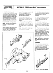
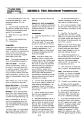
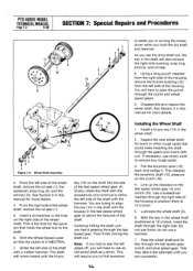
... remove the right-side bushing, snap ring, shim(s), and oil seal. 8. You will move inward until you hold the old shaft and hammer. Disassemble and inspect the wheel shaft. From the left side of the housing to the shaft. 6. Shift the Wheel Speed Lever so that the clutch is..., clutch, and slow speed gear. The shaft will have to use emery cloth to align the key (14) in the shaft with a rubber hammer. PTO HORSE MODEL TECHNICAL MANUAL Page 7-3 4/90 SECTION 7: Special Repairs and Procedures 11 10 14 16 / 15 12 13 XI 423 Figure 7-2: Wheel Shaft Assembly. 3....
... remove the right-side bushing, snap ring, shim(s), and oil seal. 8. You will move inward until you hold the old shaft and hammer. Disassemble and inspect the wheel shaft. From the left side of the housing to the shaft. 6. Shift the Wheel Speed Lever so that the clutch is..., clutch, and slow speed gear. The shaft will have to use emery cloth to align the key (14) in the shaft with a rubber hammer. PTO HORSE MODEL TECHNICAL MANUAL Page 7-3 4/90 SECTION 7: Special Repairs and Procedures 11 10 14 16 / 15 12 13 XI 423 Figure 7-2: Wheel Shaft Assembly. 3....
Technical Manual
Page 38
... Removing.. .6-4 D Disassembling Neutral plunger assembly. . .5-2 Drive Shaft PTO power unit Inspecting. . .5-4 Installing. . .5-4 Removing . . .5-3 Tiller drive shaft Inspecting. . .6-2 Installing.. .6-3 Removing. . .6-1 Tiller tine shaft Inspecting. . .6-5 Installing. . .6-5 Removing. . .6-3 E Eccentric shaft assembly Inspecting.. .5-10 Installing. . .5-10 Removing. . .5-10 Engine Removing. . .4-1 INDEX G General Information . . .1-1 H Housing cover PTO power unit Inspecting. . .5-2 Installing. . .5-2 Removing. . .5-1 Tiller tine shaft Installing. . .6-5 Removing. . .6-4 PTO HORSE MODEL...
... Removing.. .6-4 D Disassembling Neutral plunger assembly. . .5-2 Drive Shaft PTO power unit Inspecting. . .5-4 Installing. . .5-4 Removing . . .5-3 Tiller drive shaft Inspecting. . .6-2 Installing.. .6-3 Removing. . .6-1 Tiller tine shaft Inspecting. . .6-5 Installing. . .6-5 Removing. . .6-3 E Eccentric shaft assembly Inspecting.. .5-10 Installing. . .5-10 Removing. . .5-10 Engine Removing. . .4-1 INDEX G General Information . . .1-1 H Housing cover PTO power unit Inspecting. . .5-2 Installing. . .5-2 Removing. . .5-1 Tiller tine shaft Installing. . .6-5 Removing. . .6-4 PTO HORSE MODEL...