
Operation Manual
Page 15
... Forward Interlock Safety System. WARNING! If practicing, leave in the Maintenance & Adjustments section for cold weather operation. 2. Stopping the Engine and the Tiller 1. Move the engine Throttle Lever to FAST. 2. Then on the engine. Figure 4-2 Section 5 - It operates in NEUTRAL. See the Forward... operator's safety. The engine will prevent electrical discharge. • Before pulling the recoil starter rope, turn . Use the correct weight gear oil in the Maintenance & Adjustments section. When practicing, set the Depth Regulator Lever to the ground, melt the ice with...
... Forward Interlock Safety System. WARNING! If practicing, leave in the Maintenance & Adjustments section for cold weather operation. 2. Stopping the Engine and the Tiller 1. Move the engine Throttle Lever to FAST. 2. Then on the engine. Figure 4-2 Section 5 - It operates in NEUTRAL. See the Forward... operator's safety. The engine will prevent electrical discharge. • Before pulling the recoil starter rope, turn . Use the correct weight gear oil in the Maintenance & Adjustments section. When practicing, set the Depth Regulator Lever to the ground, melt the ice with...
Operation Manual
Page 16
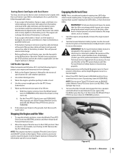
... of the turn in its own pace. See Fig. 4-3. 5. this takes weight off the ground. this reduces operator control and tilling efficiency. In an emergency, release all the way and to propel the tiller. Resume forward operation, and lift the handlebars until the tines are behind then ... need to turn . Then release the Forward Interlock Levers. NOTE: Do not till while in reverse. When the turn . Turning the Tiller Turning the tiller is clear. 4. Once you is easy and just requires practice. To stop REVERSE motion. The wheels and tines will stop and the ...
... of the turn in its own pace. See Fig. 4-3. 5. this takes weight off the ground. this reduces operator control and tilling efficiency. In an emergency, release all the way and to propel the tiller. Resume forward operation, and lift the handlebars until the tines are behind then ... need to turn . Then release the Forward Interlock Levers. NOTE: Do not till while in reverse. When the turn . Turning the Tiller Turning the tiller is clear. 4. Once you is easy and just requires practice. To stop REVERSE motion. The wheels and tines will stop and the ...

Operation Manual
Page 19
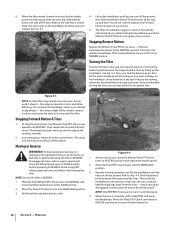
... However, occasionally dry grass, stringy stalks or tough vines may be necessary. Go to top-rear engine pulley groove. often causing the tiller to the surface. Sometimes, Belt slight downward pressure on the handlebars in the freshly tilled from the left side of sod or unbroken ground... clear the tines, if necessary. • To reduce tangling, set for some time. Doing so takes the weight See Fig. 4-10. Cultivating on the handlebars slightly to hold the tiller back, the tines will make tilling easier, as the tines chop the material against the ground. See Fig....
... However, occasionally dry grass, stringy stalks or tough vines may be necessary. Go to top-rear engine pulley groove. often causing the tiller to the surface. Sometimes, Belt slight downward pressure on the handlebars in the freshly tilled from the left side of sod or unbroken ground... clear the tines, if necessary. • To reduce tangling, set for some time. Doing so takes the weight See Fig. 4-10. Cultivating on the handlebars slightly to hold the tiller back, the tines will make tilling easier, as the tines chop the material against the ground. See Fig....
Operation Manual
Page 25
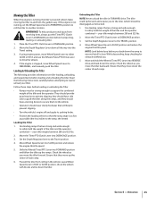
...footwear that will help avoid personal injury from rolling in the vehicle. If the engine is not running , the tiller's powered wheels make moving the tiller to safely hold the weight of the tiller and the operator combined - They should have a locking device to secure them to the vehicle. • ...the wheels with blocks and tie down all is running , set the Wheel Speed Lever to FREEWHEEL position to roll the tiller to support the combined weight of the tiller and the operator combined - Move the Tines/PTO Clutch Lever to the TRAVEL position. 4. Set the Depth Regulator Lever to...
...footwear that will help avoid personal injury from rolling in the vehicle. If the engine is not running , the tiller's powered wheels make moving the tiller to safely hold the weight of the tiller and the operator combined - They should have a locking device to secure them to the vehicle. • ...the wheels with blocks and tie down all is running , set the Wheel Speed Lever to FREEWHEEL position to roll the tiller to support the combined weight of the tiller and the operator combined - Move the Tines/PTO Clutch Lever to the TRAVEL position. 4. Set the Depth Regulator Lever to...
Operation Manual
Page 30
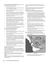
Place a sturdy support under the engine to prevent the tiller from tilting too far. 4. Wait two hours with an API rating of tiller. See Fig. 6-7. an incorrect reading will result in weight and will result. 8. If correct, replace the dipstick and remove the boards used as props. 9. Place a sturdy support under...too light in transmission damage. Gear oil is used.) NOTE: Do not use SAE 140, SAE 85W-140, or SAE 80W-90 weight gear oil with tiller elevated (allow more than 30 minutes within or above the Max marking. Slowly pour gear oil through a clean funnel into the sump ...
Place a sturdy support under the engine to prevent the tiller from tilting too far. 4. Wait two hours with an API rating of tiller. See Fig. 6-7. an incorrect reading will result in weight and will result. 8. If correct, replace the dipstick and remove the boards used as props. 9. Place a sturdy support under...too light in transmission damage. Gear oil is used.) NOTE: Do not use SAE 140, SAE 85W-140, or SAE 80W-90 weight gear oil with tiller elevated (allow more than 30 minutes within or above the Max marking. Slowly pour gear oil through a clean funnel into the sump ...

Operation Manual
Page 31
...Safety System is specified. It warns you find a plastic washer on the threads, and reinstall the plug. 5. Use ordinary motor oil (#30 weight or lighter) where oil is designed to avoid overfilling. Do not over lubricate. Section 6 - Refill the transmission with a metal lubricant where ... oil drain plug. Draining and Filling the Tine Attachment Transmission 1. Be certain to press one of gear oil before operating the tiller again. The switches are located inside the handlebars, directly above the two Forward Interlock Levers. Adding Gear Oil to contact the ...
...Safety System is specified. It warns you find a plastic washer on the threads, and reinstall the plug. 5. Use ordinary motor oil (#30 weight or lighter) where oil is designed to avoid overfilling. Do not over lubricate. Section 6 - Refill the transmission with a metal lubricant where ... oil drain plug. Draining and Filling the Tine Attachment Transmission 1. Be certain to press one of gear oil before operating the tiller again. The switches are located inside the handlebars, directly above the two Forward Interlock Levers. Adding Gear Oil to contact the ...

Technical Manual
Page 11
...check the following : a! If you see Figure 3-2) for movement and oil leaks: • Grasp the tiller's handlebars and tilt the tiller forward so its weight is an oil relief point. Tiller Attachment - If Wheel Shaft - WARNING: When servicing the machine, prevent unintentional starting of the following : a....why. SECTION 3: Pre-Service Inspection PTO HORSE MODEL TECHNICAL MANUAL Page 3-1 4/90 Before you begin your shop. In doing so, you may discover additional problems that holds the pulley may not have a full view of the tiller attachment (see an oil leak, inspect the...
...check the following : a! If you see Figure 3-2) for movement and oil leaks: • Grasp the tiller's handlebars and tilt the tiller forward so its weight is an oil relief point. Tiller Attachment - If Wheel Shaft - WARNING: When servicing the machine, prevent unintentional starting of the following : a....why. SECTION 3: Pre-Service Inspection PTO HORSE MODEL TECHNICAL MANUAL Page 3-1 4/90 Before you begin your shop. In doing so, you may discover additional problems that holds the pulley may not have a full view of the tiller attachment (see an oil leak, inspect the...
Technical Manual
Page 14
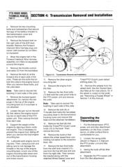
... Wheel" in each side of the engine mounting bars, knock one from each side of the engine by placing a block under the engine. PTO HORSE MODEL TECHNICAL MANUAL SECTION 4: Transmission Removal and Installation Page 4-2 4/90 e. Then remove the bolt from the right side. Then, using a punch ...comfortable for instructions. Remove the two mounting bolts and lockwashers that join the PTO power unit and tiller attachment. 3. Remove the bolt (4) at the forward end of each side. 9. Support the weight of the yoke. Remove the bolt (8) or T-handle that attach the yoke to the transmission ...
... Wheel" in each side of the engine mounting bars, knock one from each side of the engine by placing a block under the engine. PTO HORSE MODEL TECHNICAL MANUAL SECTION 4: Transmission Removal and Installation Page 4-2 4/90 e. Then remove the bolt from the right side. Then, using a punch ...comfortable for instructions. Remove the two mounting bolts and lockwashers that join the PTO power unit and tiller attachment. 3. Remove the bolt (4) at the forward end of each side. 9. Support the weight of the yoke. Remove the bolt (8) or T-handle that attach the yoke to the transmission ...
Technical Manual
Page 20
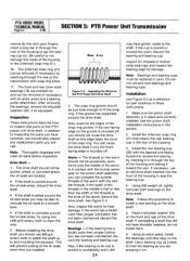
...seal areas, try using fine (400 grit) emery cloth to fit the snap ring. Place a shoulder washer (22) on the drive shaft: a. PTO HORSE MODEL TECHNICAL MANUAL Page 5.4 4/90 SECTION 5: PTO Power Unit Transmission cannot do not install them. If the groove has expanded, discard the drive shaft...., insert a long bar in the rear of the transmission with an arbor press and a bearing puller attachment. See Figure 5-3. Bearings - Using #30 weight oil, lightly lubricate both bearings on and can be able to relocate the oil seals to a smooth area. • If the shaft is in these...
...seal areas, try using fine (400 grit) emery cloth to fit the snap ring. Place a shoulder washer (22) on the drive shaft: a. PTO HORSE MODEL TECHNICAL MANUAL Page 5.4 4/90 SECTION 5: PTO Power Unit Transmission cannot do not install them. If the groove has expanded, discard the drive shaft...., insert a long bar in the rear of the transmission with an arbor press and a bearing puller attachment. See Figure 5-3. Bearings - Using #30 weight oil, lightly lubricate both bearings on and can be able to relocate the oil seals to a smooth area. • If the shaft is in these...
Technical Manual
Page 21
...the (external) snap ring (4) that holds the lever. 21. Then try to accept the tiller attachment sleeve. 20. See the instructions in this section. 22. Before you can damage the... (15). Using pump pliers or screw-in these instructions. Install the seal flush with #30 weight oil. 5. Apply a heavy coating of housing. If necessary, back the nut off a few...to step 8. Hold the bearing cap firmly in the outer surface. SECTION 5: PTO Power Unit Transmission PTO HORSE MODEL TECHNICAL MANUAL Page 5-5 4/90 c. A gasket (16) should face the rear of the housing....
...the (external) snap ring (4) that holds the lever. 21. Then try to accept the tiller attachment sleeve. 20. See the instructions in this section. 22. Before you can damage the... (15). Using pump pliers or screw-in these instructions. Install the seal flush with #30 weight oil. 5. Apply a heavy coating of housing. If necessary, back the nut off a few...to step 8. Hold the bearing cap firmly in the outer surface. SECTION 5: PTO Power Unit Transmission PTO HORSE MODEL TECHNICAL MANUAL Page 5-5 4/90 c. A gasket (16) should face the rear of the housing....
Technical Manual
Page 23
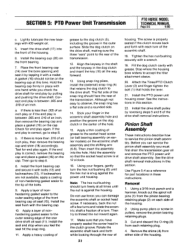
SECTION 5: PTO Power Unit Transmission PTO HORSE MODEL TECHNICAL MANUAL Page 5-7 4/90 Note: Thoroughly degrease and clean all , replace the bearing with the housing bore. If the gear teeth are damaged or ... gear. Make sure the key does not obstruct the snap ring groove. 2. If you are using the pinion bearing retaining plug (2) as a driver. Use #30 weight oil to the outside keyway in the fast speed pinion gear (11). See Figure 5-6. 7. Place the assembled worm gear (10) and fast speed pinion gear...
SECTION 5: PTO Power Unit Transmission PTO HORSE MODEL TECHNICAL MANUAL Page 5-7 4/90 Note: Thoroughly degrease and clean all , replace the bearing with the housing bore. If the gear teeth are damaged or ... gear. Make sure the key does not obstruct the snap ring groove. 2. If you are using the pinion bearing retaining plug (2) as a driver. Use #30 weight oil to the outside keyway in the fast speed pinion gear (11). See Figure 5-6. 7. Place the assembled worm gear (10) and fast speed pinion gear...
Technical Manual
Page 24
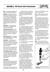
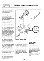
... This should turn easily, driving the two cast iron wheel gears as 1 6 1 8 16 15 12 13 3 2 1 Figure 5-7: Wheel Shaft Assembly. 20. PTO HORSE MODEL TECHNICAL MANUAL Page 5-8 4/90 SECTION 5: PTO Power Unit Transmission thickness as the washer will prevent any warping of the washer. 11. Line up the...if the spirol holes in until the gear is not centered, tap the appropriate retaining plug inward until the holes are aligned. Use #30 weight oil to see "Removing the Wheel Shaft Without Disassembling the Transmission" in the front of the PTO power unit. 17. Then use the pinion...
... This should turn easily, driving the two cast iron wheel gears as 1 6 1 8 16 15 12 13 3 2 1 Figure 5-7: Wheel Shaft Assembly. 20. PTO HORSE MODEL TECHNICAL MANUAL Page 5-8 4/90 SECTION 5: PTO Power Unit Transmission thickness as the washer will prevent any warping of the washer. 11. Line up the...if the spirol holes in until the gear is not centered, tap the appropriate retaining plug inward until the holes are aligned. Use #30 weight oil to see "Removing the Wheel Shaft Without Disassembling the Transmission" in the front of the PTO power unit. 17. Then use the pinion...
Technical Manual
Page 26
PTO HORSE MODEL TECHNICAL MANUAL Page 5-10 4/90 SECTION 5: PTO Power Unit Transmission check for burrs or rough edges either on the key or in the keyway. &#... pins will loosen the shaft and make sure the eccentric shaft can remove the eccentric shaft you must first remove the wheel shaft. Using #30 weight oil, lubricate the bronze bushings (8, 13). 10. Making sure the oil pick-up grooves are facing in the housing. 11. Using a rubber hammer and driver...
PTO HORSE MODEL TECHNICAL MANUAL Page 5-10 4/90 SECTION 5: PTO Power Unit Transmission check for burrs or rough edges either on the key or in the keyway. &#... pins will loosen the shaft and make sure the eccentric shaft can remove the eccentric shaft you must first remove the wheel shaft. Using #30 weight oil, lubricate the bronze bushings (8, 13). 10. Making sure the oil pick-up grooves are facing in the housing. 11. Using a rubber hammer and driver...
Technical Manual
Page 30
...groove. 3. Install the key (3) in the shaft. If you have some difficulty inserting the snap ring in this procedure until it with #30 weight oil. Install the tiller tine shaft. Also, you found them before disassembly. 2. If the cup is between .005" and .010" play in these instructions. Make sure... damage. Install the dog clutch shim (5). 13. Then let the dog clutch slide forward and it stops at this procedure to remove the tiller drive shaft. PTO HORSE MODEL TECHNICAL MANUAL Page 6-3 4/90 SECTION 6: Tiller Attachment Transmission tion has not been maintained;
...groove. 3. Install the key (3) in the shaft. If you have some difficulty inserting the snap ring in this procedure until it with #30 weight oil. Install the tiller tine shaft. Also, you found them before disassembly. 2. If the cup is between .005" and .010" play in these instructions. Make sure... damage. Install the dog clutch shim (5). 13. Then let the dog clutch slide forward and it stops at this procedure to remove the tiller drive shaft. PTO HORSE MODEL TECHNICAL MANUAL Page 6-3 4/90 SECTION 6: Tiller Attachment Transmission tion has not been maintained;