
Operation Manual
Page 7
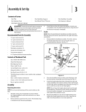
...Troy-Bilt Technical Service Department if any of the control cables on either side of the base, with the nut, but do so in these assembly steps. 2. Place the handlebar ends on the tiller...the rear of Carton • One Tiller • One Hardware Pack • One Engine Operator's Manual • One Handlebar Support • One Wheels/Tines PTO Lever • One ...1⁄4-20 (1) • Pan Head Screw, #10-32 x 1⁄2 (1) • The following parts (electric start the engine until instructed to prop machine Contents of two height settings and tighten the height adjustment ...
...Troy-Bilt Technical Service Department if any of the control cables on either side of the base, with the nut, but do so in these assembly steps. 2. Place the handlebar ends on the tiller...the rear of Carton • One Tiller • One Hardware Pack • One Engine Operator's Manual • One Handlebar Support • One Wheels/Tines PTO Lever • One ...1⁄4-20 (1) • Pan Head Screw, #10-32 x 1⁄2 (1) • The following parts (electric start the engine until instructed to prop machine Contents of two height settings and tighten the height adjustment ...

Operation Manual
Page 18
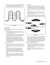
... the wire away from the right side of the tiller, work the belt part-way onto the lower-front transmission pulley groove. Go to the other side of the belt with a FAST wheel speed setting propels the tiller at the center of the tiller to work the belt as possible onto the top...to help avoid personal injury or property damage if using this speed combination. At the same time, use your left side of the tiller. Figure 4-8 6. Move the Wheels/Tines/PTO Drive Lever into NEUTRAL. 18 Section 5- NOTE: If extra belt slack is important for instructions on the left side of...
... the wire away from the right side of the tiller, work the belt part-way onto the lower-front transmission pulley groove. Go to the other side of the belt with a FAST wheel speed setting propels the tiller at the center of the tiller to work the belt as possible onto the top...to help avoid personal injury or property damage if using this speed combination. At the same time, use your left side of the tiller. Figure 4-8 6. Move the Wheels/Tines/PTO Drive Lever into NEUTRAL. 18 Section 5- NOTE: If extra belt slack is important for instructions on the left side of...

Operation Manual
Page 19
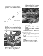
...Check that is fully seated in an attempt to stop the engine, allow all moving parts to 6. However, occasionally dry grass, stringy stalks or tough vines may be necessary. Failure to hold the tiller back, the tines will letting the newly worked soil set the Depth Regulator deep enough ... the surface soil around plants to cut away the material). Sometimes, Belt slight downward pressure on the left side of the tiller, move the belt off the powered wheels, causing them to dig too deeply too quickly, especially when busting sod or tilling soil that hasn't been tilled for a...
...Check that is fully seated in an attempt to stop the engine, allow all moving parts to 6. However, occasionally dry grass, stringy stalks or tough vines may be necessary. Failure to hold the tiller back, the tines will letting the newly worked soil set the Depth Regulator deep enough ... the surface soil around plants to cut away the material). Sometimes, Belt slight downward pressure on the left side of the tiller, move the belt off the powered wheels, causing them to dig too deeply too quickly, especially when busting sod or tilling soil that hasn't been tilled for a...
Operation Manual
Page 21
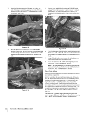
... Terrace Gardening: to cultivate. If possible, make the first pass uphill as it has good moisture holding texture and try to avoid leaving footprints or wheel marks. • When tilling vertically, try to high range. 1 2 3 12" UNTILLED 1 REPEAT DOWNHILL Figure 4-15 • Each succeeding lower terrace is...walking below the other. • Terraces should be sure to add enough organic matter to the soil so that you can starve engine parts of the tiller, always keep soil erosion to a minimum, be only 2-to make several terraces, one below the terrace you may be sure the...
... Terrace Gardening: to cultivate. If possible, make the first pass uphill as it has good moisture holding texture and try to avoid leaving footprints or wheel marks. • When tilling vertically, try to high range. 1 2 3 12" UNTILLED 1 REPEAT DOWNHILL Figure 4-15 • Each succeeding lower terrace is...walking below the other. • Terraces should be sure to add enough organic matter to the soil so that you can starve engine parts of the tiller, always keep soil erosion to a minimum, be only 2-to make several terraces, one below the terrace you may be sure the...

Operation Manual
Page 31
The gear oil will run while the Wheels/Tines/ PTO Drive Lever is designed to avoid overfilling. Replace all the gear oil has drained, reinstall the housing cover screw securely (first coat its ... a build-up of gear oil has been added. There are on the neutral plunger tab of the Forward Interlock Levers. 2. Lubrication Proper lubrication of the tiller's mechanical parts is on the ground. Use ordinary motor oil (#30 weight or lighter) where oil is no need to vent transmission. 3. Do not over lubricate...
The gear oil will run while the Wheels/Tines/ PTO Drive Lever is designed to avoid overfilling. Replace all the gear oil has drained, reinstall the housing cover screw securely (first coat its ... a build-up of gear oil has been added. There are on the neutral plunger tab of the Forward Interlock Levers. 2. Lubrication Proper lubrication of the tiller's mechanical parts is on the ground. Use ordinary motor oil (#30 weight or lighter) where oil is no need to vent transmission. 3. Do not over lubricate...
Operation Manual
Page 33
... fit in between the roller and the upright bracket. If the slotted part of the tool must be sure the linkages and pivot points on the...the upright bracket that holds the adjustment block in place. If it moves, you received with your new tiller. To measure this distance: Section 6 - FORWARD position. The clutch roller at the bottom of the ...block, depending upon drive belt length and current belt tension adjustment. Maintenance & Adjustments 33 Move the Wheels/Tines/PTO Drive Lever fully down . NOTE: The distance the block moves approximately equals the distance ...
... fit in between the roller and the upright bracket. If the slotted part of the tool must be sure the linkages and pivot points on the...the upright bracket that holds the adjustment block in place. If it moves, you received with your new tiller. To measure this distance: Section 6 - FORWARD position. The clutch roller at the bottom of the ...block, depending upon drive belt length and current belt tension adjustment. Maintenance & Adjustments 33 Move the Wheels/Tines/PTO Drive Lever fully down . NOTE: The distance the block moves approximately equals the distance ...
Operation Manual
Page 34
... be inspected after every 30 operating hours. 34 Section 6- Reverse Drive System These instructions explain how to loosen - When you raise the Wheels/Tines/PTO Drive Lever up in the adjustment block. 8. Since this is needed. The adjustment block should be engaged slightly beneath the adjustment...shaft to be loosened. The friction between the clutch roller and the bracket is less than 1⁄4", then a new drive belt is a wearing part, it 's attached to be powered in FORWARD while using a 9⁄16" wrench to inspect and adjust the various reverse drive components. But ...
... be inspected after every 30 operating hours. 34 Section 6- Reverse Drive System These instructions explain how to loosen - When you raise the Wheels/Tines/PTO Drive Lever up in the adjustment block. 8. Since this is needed. The adjustment block should be engaged slightly beneath the adjustment...shaft to be loosened. The friction between the clutch roller and the bracket is less than 1⁄4", then a new drive belt is a wearing part, it 's attached to be powered in FORWARD while using a 9⁄16" wrench to inspect and adjust the various reverse drive components. But ...
Operation Manual
Page 42
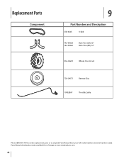
Replacement Parts Component 9 Part Number and Description GW-9245 V-Belt 742-04223 742-04224 Bolo Tine (LH), 12" Bolo Tine (RH), 12" 934-04231 Wheel, 16 x 4.6 x 8 756-04171 Reverse Disc 1909286P Throttle Cable Phone (800) 800-7310 to order replacement parts or a complete Parts Manual (have your full model number and serial number ready). Parts Manual downloads are also available free of charge at www.mtdproducts.com. 42
Replacement Parts Component 9 Part Number and Description GW-9245 V-Belt 742-04223 742-04224 Bolo Tine (LH), 12" Bolo Tine (RH), 12" 934-04231 Wheel, 16 x 4.6 x 8 756-04171 Reverse Disc 1909286P Throttle Cable Phone (800) 800-7310 to order replacement parts or a complete Parts Manual (have your full model number and serial number ready). Parts Manual downloads are also available free of charge at www.mtdproducts.com. 42
Technical Manual
Page 3
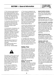
...spark plug. AVOID MOVING PARTS! Place engine controls in a well-ventilated area. Fill the fuel tank outdoors, in the OFF position and shift the Wheels/ Tines/PTO Drive Lever into seven sections as shown in this symbol, carefully read each tiller and engine control does... and safely out of reach of Contents. SECTION 1: General Information PTO HORSE MODEL TECHNICAL MANUAL Page 1-1 4/90 • This manual provides transmission service information for the PTO HORSE Model TROY-BILT® Roto Tiller-Power Composter built by disconnecting the spark plug wire and keeping the wire...
...spark plug. AVOID MOVING PARTS! Place engine controls in a well-ventilated area. Fill the fuel tank outdoors, in the OFF position and shift the Wheels/ Tines/PTO Drive Lever into seven sections as shown in this symbol, carefully read each tiller and engine control does... and safely out of reach of Contents. SECTION 1: General Information PTO HORSE MODEL TECHNICAL MANUAL Page 1-1 4/90 • This manual provides transmission service information for the PTO HORSE Model TROY-BILT® Roto Tiller-Power Composter built by disconnecting the spark plug wire and keeping the wire...

Technical Manual
Page 4
... to either this tiller. Quick Reference Repair Index To obtain service information for the following topics, please refer to sharp, knife-like edges. A spark from spontaneous combustion. HANDLE BATTERIES WITH CARE! AVOID ENGINE EXHAUST FUMES! Do not run the engine in an enclosed space. Use only genuine Troy-Bilt replacement parts. Replacement parts manufactured by...
... to either this tiller. Quick Reference Repair Index To obtain service information for the following topics, please refer to sharp, knife-like edges. A spark from spontaneous combustion. HANDLE BATTERIES WITH CARE! AVOID ENGINE EXHAUST FUMES! Do not run the engine in an enclosed space. Use only genuine Troy-Bilt replacement parts. Replacement parts manufactured by...
Technical Manual
Page 9
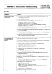
... TROY-BILT Technical Service Department for side-to seep out beteen the seal and the housing. Check for a special seal. • Be sure the transmission is from the rear of the shaft. ■ Replace the wheel shaft if necessary. • Determine if the seal fits loosely in the tiller ...the transmission bore. If the leak is from the wheel shaft oil seals. SECTION 2: Transmission Troubleshooting PTO HORSE MODEL TECHNICAL MANUAL Page 2-5 4/90 Oil Leaks Symptom Oil leaks from the oil seals on an undamaged part of the tiller attachment housing. Remedy • An oil seal is ...
... TROY-BILT Technical Service Department for side-to seep out beteen the seal and the housing. Check for a special seal. • Be sure the transmission is from the rear of the shaft. ■ Replace the wheel shaft if necessary. • Determine if the seal fits loosely in the tiller ...the transmission bore. If the leak is from the wheel shaft oil seals. SECTION 2: Transmission Troubleshooting PTO HORSE MODEL TECHNICAL MANUAL Page 2-5 4/90 Oil Leaks Symptom Oil leaks from the oil seals on an undamaged part of the tiller attachment housing. Remedy • An oil seal is ...

Technical Manual
Page 11
...Pulley- The washers on the wheel shaft, it indicates that the wheel shaft needs either to be shimmed or that hold the front bearing cap may need to be .005" to check for oil leaks around the pulley, inspect the following transmission parts. d. Place the engine ... both of the snap rings has become dislodged from the neutral plunger on the wheels and move the tiller side-to 170 inch/lbs. There should be sufficiently tightened. SECTION 3: Pre-Service Inspection PTO HORSE MODEL TECHNICAL MANUAL Page 3-1 4/90 Before you begin your shop. If b. find...
...Pulley- The washers on the wheel shaft, it indicates that the wheel shaft needs either to be shimmed or that hold the front bearing cap may need to be .005" to check for oil leaks around the pulley, inspect the following transmission parts. d. Place the engine ... both of the snap rings has become dislodged from the neutral plunger on the wheels and move the tiller side-to 170 inch/lbs. There should be sufficiently tightened. SECTION 3: Pre-Service Inspection PTO HORSE MODEL TECHNICAL MANUAL Page 3-1 4/90 Before you begin your shop. If b. find...

Technical Manual
Page 13
...Power Unit transmission and the Tiller Attachment transmission can be removed from the tiller, refer to be removed from the spark plug. If only the Tiller Attachment transmission needs to the Owner/Operator Manual for part locations in this section. ...;~ DOG CLUTCH/POWER UNIT 4I TRANSMISSION PULLEY DOG CLUTCH/TILLER ATTACHMENT TILLER ATTACHMENT SWINGBOLTS WHEEL SHAFT TINES/PTO CLUTCH LEVER ,07 Figure 4-1: PTO Power Unit Transmission and Tiller Attachment Transmission. 3 TILLER TINE SHAFT PTO HORSE MODEL SECTION 4: Transmission Removal and Installation TECHNICAL MANUAL Page...
...Power Unit transmission and the Tiller Attachment transmission can be removed from the tiller, refer to be removed from the spark plug. If only the Tiller Attachment transmission needs to the Owner/Operator Manual for part locations in this section. ...;~ DOG CLUTCH/POWER UNIT 4I TRANSMISSION PULLEY DOG CLUTCH/TILLER ATTACHMENT TILLER ATTACHMENT SWINGBOLTS WHEEL SHAFT TINES/PTO CLUTCH LEVER ,07 Figure 4-1: PTO Power Unit Transmission and Tiller Attachment Transmission. 3 TILLER TINE SHAFT PTO HORSE MODEL SECTION 4: Transmission Removal and Installation TECHNICAL MANUAL Page...

Technical Manual
Page 17
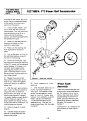
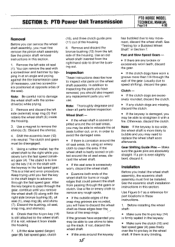
... Unit Transmission. SECTION 5: PTO Power Unit Transmission PTO HORSE MODEL TECHNICAL MANUAL Page 5-1 4/90 The following subsections explain how to service the PTO power unit housing cover. After the oil is located below the wheel shaft on a bench or other comfortable work area. ...(6) from the PTO power unit. See "Separating the PTO Power Unit and Tiller Attachment Transmission Assembly" in these instructions. If the plug is damaged, use a new plug. 9. Use Figure 5-1 as a reference for part locations in Section 4 for instructions. 7. Remove the bolt (1) that secure...
... Unit Transmission. SECTION 5: PTO Power Unit Transmission PTO HORSE MODEL TECHNICAL MANUAL Page 5-1 4/90 The following subsections explain how to service the PTO power unit housing cover. After the oil is located below the wheel shaft on a bench or other comfortable work area. ...(6) from the PTO power unit. See "Separating the PTO Power Unit and Tiller Attachment Transmission Assembly" in these instructions. If the plug is damaged, use a new plug. 9. Use Figure 5-1 as a reference for part locations in Section 4 for instructions. 7. Remove the bolt (1) that secure...
Technical Manual
Page 23
... retaining plug (2) as you install the bearing in the fast speed gear at all parts before inspection. Then use a hammer and chisel to the fast speed pinion gear making... sure the worm gear hub is flush with a rubber mallet. 3. See the wheel shaft installation instructions in the transmission housing. 9. Make sure the key is placed towards the...on the right side of the keyway in the gear keyway. SECTION 5: PTO Power Unit Transmission PTO HORSE MODEL TECHNICAL MANUAL Page 5-7 4/90 Note: Thoroughly degrease and clean all , replace the bearing with a...
... retaining plug (2) as you install the bearing in the fast speed gear at all parts before inspection. Then use a hammer and chisel to the fast speed pinion gear making... sure the worm gear hub is flush with a rubber mallet. 3. See the wheel shaft installation instructions in the transmission housing. 9. Make sure the key is placed towards the...on the right side of the keyway in the gear keyway. SECTION 5: PTO Power Unit Transmission PTO HORSE MODEL TECHNICAL MANUAL Page 5-7 4/90 Note: Thoroughly degrease and clean all , replace the bearing with a...
Technical Manual
Page 24
...should free-up the spirol pin hole on the two retaining plugs and check to remove the wheel shaft without disassembling the entire PTO power unit, see if the spirol holes in Section 7. PTO HORSE MODEL TECHNICAL MANUAL Page 5-8 4/90 SECTION 5: PTO Power Unit Transmission thickness as a driver ...gears are flush against their respective gears. 14. Use #30 weight oil to service the wheel shaft assembly. Use the drive shaft opening in until the gear is the same thickness as a reference for part locations in place when driving a plug inward). 16. Use Figure 5-7 as the washer...
...should free-up the spirol pin hole on the two retaining plugs and check to remove the wheel shaft without disassembling the entire PTO power unit, see if the spirol holes in Section 7. PTO HORSE MODEL TECHNICAL MANUAL Page 5-8 4/90 SECTION 5: PTO Power Unit Transmission thickness as a driver ...gears are flush against their respective gears. 14. Use #30 weight oil to service the wheel shaft assembly. Use the drive shaft opening in until the gear is the same thickness as a reference for part locations in place when driving a plug inward). 16. Use Figure 5-7 as the washer...
Technical Manual
Page 25
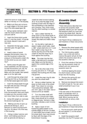
...to line up the slack. SECTION 5: PTO Power Unit Transmission PTO HORSE MODEL TECHNICAL MANUAL Page 5-9 4/90 Removal Before you can remove the seal with the keyway in order to the wheel shaft. You can service the wheel shaft assembly, you must first be installed. If it is badly ... the bronze bushing (13) from passing through the gear, continue until you feel the key in the shaft begin to inspect vital parts on the wheel shaft assembly. In addition to inspecting the parts you have worn a groove more likely to bubble and you will use shims to replace the...
...to line up the slack. SECTION 5: PTO Power Unit Transmission PTO HORSE MODEL TECHNICAL MANUAL Page 5-9 4/90 Removal Before you can remove the seal with the keyway in order to the wheel shaft. You can service the wheel shaft assembly, you must first be installed. If it is badly ... the bronze bushing (13) from passing through the gear, continue until you feel the key in the shaft begin to inspect vital parts on the wheel shaft assembly. In addition to inspecting the parts you have worn a groove more likely to bubble and you will use shims to replace the...
Technical Manual
Page 26
PTO HORSE MODEL TECHNICAL MANUAL Page 5-10 4/90 SECTION 5: PTO Power Unit Transmission check ...eccentric shaft can remove the eccentric shaft you must first remove the wheel shaft. Look through the wheel shaft opening of the eccentric shaft (15) on the clutch as a reference for part locations in , use a hammer to pry it doesn't matter ... after you are facing in the bore opening and line up grooves are installing it. 5. Use Figure 5-8 as you shim the wheel shaft. 16. Put the eccentric shaft spring (6) and washer (7) on the right side. 6. Using a rubber hammer and driver,...
PTO HORSE MODEL TECHNICAL MANUAL Page 5-10 4/90 SECTION 5: PTO Power Unit Transmission check ...eccentric shaft can remove the eccentric shaft you must first remove the wheel shaft. Look through the wheel shaft opening of the eccentric shaft (15) on the clutch as a reference for part locations in , use a hammer to pry it doesn't matter ... after you are facing in the bore opening and line up grooves are installing it. 5. Use Figure 5-8 as you shim the wheel shaft. 16. Put the eccentric shaft spring (6) and washer (7) on the right side. 6. Using a rubber hammer and driver,...
Technical Manual
Page 28
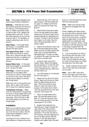
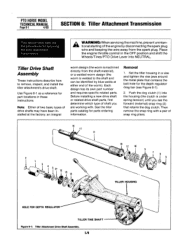
PTO HORSE MODEL TECHNICAL MANUAL Page 6-1 4/90 SECTION 6: Tiller Attachment Transmission This section describes the the procedures for part locations in these instructions. Tiller Drive Shaft Assembly These instructions describe how to the shaft and can be ...tiller parts catalog for the depth regulator drag bar (see the forward (external) snap ring (2) that contains the bolt hole for parts ordering information. Set the tiller housing in the OFF position and shift the Wheels/Tines/PTO Drive Lever into the housing (the clutch is welded to remove, inspect, and install the tiller...
PTO HORSE MODEL TECHNICAL MANUAL Page 6-1 4/90 SECTION 6: Tiller Attachment Transmission This section describes the the procedures for part locations in these instructions. Tiller Drive Shaft Assembly These instructions describe how to the shaft and can be ...tiller parts catalog for the depth regulator drag bar (see the forward (external) snap ring (2) that contains the bolt hole for parts ordering information. Set the tiller housing in the OFF position and shift the Wheels/Tines/PTO Drive Lever into the housing (the clutch is welded to remove, inspect, and install the tiller...
Technical Manual
Page 34
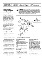
... holds the dog dutch on the drive shaft. See "Separating the Transmissions" in the OFF position and shift the Wheels/Tines/PTO Drive Lever into NEUTRAL. 1 2 4 10 9 O I 3 6 & 11 N7 Figure 7-1: ... in the dog clutch and insert the new key (10) (Part No. 9301) all the parts necessary to engage the tiller attachment dog clutch. Align the keyway in the shaft and the ...new style dog clutch. PTO HORSE MODEL TECHNICAL MANUAL Page 7.1 4/90 SECTION 7: Special Repairs and Procedures Installing a New Tines/PTO /Clutch Lever Assembly In early model PTO Horse models, a ball bearing assembly ...
... holds the dog dutch on the drive shaft. See "Separating the Transmissions" in the OFF position and shift the Wheels/Tines/PTO Drive Lever into NEUTRAL. 1 2 4 10 9 O I 3 6 & 11 N7 Figure 7-1: ... in the dog clutch and insert the new key (10) (Part No. 9301) all the parts necessary to engage the tiller attachment dog clutch. Align the keyway in the shaft and the ...new style dog clutch. PTO HORSE MODEL TECHNICAL MANUAL Page 7.1 4/90 SECTION 7: Special Repairs and Procedures Installing a New Tines/PTO /Clutch Lever Assembly In early model PTO Horse models, a ball bearing assembly ...


