
Operation Manual
Page 7
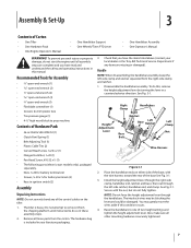
...local dealer or the Troy-Bilt Technical Service Department if any of the control cables on either side of the base, with the nut, but do not start models only), packaged separately...; Tire pressure gauge (1) • 4-1⁄2" high wood block to one of Carton • One Tiller • One Hardware Pack • One Engine Operator's Manual • One Handlebar Support • ...20 (1) • Pan Head Screw, #10-32 x 1⁄2 (1) • The following parts (electric start the engine until instructed to remove it from the right-side clamp and ratchet. 1. To prevent personal injury...
...local dealer or the Troy-Bilt Technical Service Department if any of the control cables on either side of the base, with the nut, but do not start models only), packaged separately...; Tire pressure gauge (1) • 4-1⁄2" high wood block to one of Carton • One Tiller • One Hardware Pack • One Engine Operator's Manual • One Handlebar Support • ...20 (1) • Pan Head Screw, #10-32 x 1⁄2 (1) • The following parts (electric start the engine until instructed to remove it from the right-side clamp and ratchet. 1. To prevent personal injury...
Operation Manual
Page 8
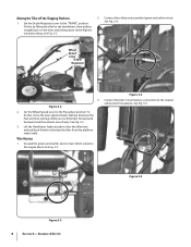
See Fig. 3-4. Set the Wheel Speed Lever to the engine block. See Fig. 3-2 3. Ground the green (and red for electric start tillers) wire(s) to the Freewheel position. Figure 3-5 Figure 3-3 8 Section 3- Set the Depth Regulator Lever to the neutral safety switch receptacle. Wire Harness 1. ...Lever Depth Regulator Lever 3. To do this by lifting the tiller by the handlebars, then pulling straight back on the lever and sliding down to dislodge the tiller from the platform wheel wells. Figure 3-4 Connect the tiller's main harness connection to the "TRAVEL" position. Lift the ...
See Fig. 3-4. Set the Wheel Speed Lever to the engine block. See Fig. 3-2 3. Ground the green (and red for electric start tillers) wire(s) to the Freewheel position. Figure 3-5 Figure 3-3 8 Section 3- Set the Depth Regulator Lever to the neutral safety switch receptacle. Wire Harness 1. ...Lever Depth Regulator Lever 3. To do this by lifting the tiller by the handlebars, then pulling straight back on the lever and sliding down to dislodge the tiller from the platform wheel wells. Figure 3-4 Connect the tiller's main harness connection to the "TRAVEL" position. Lift the ...
Operation Manual
Page 11
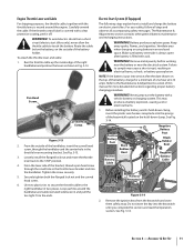
...protective coating, peel it off. If the throttle control label is covered with the throttle lever, is always open after the date shown on electric start tillers. Route the cable below the battery, on the hold -down clamp. Run the throttle cable up the inside edge of the battery holder... into the handlebar. Assembly & Set-Up 11 Pan Head Screw Curved Head Screw Figure 3-13 2. Loop each tie around the engine. Electric Start System (If Equipped) The following steps explain how to touch the battery. Make sure battery vent tube is wound around the handlebar and cable...
...protective coating, peel it off. If the throttle control label is covered with the throttle lever, is always open after the date shown on electric start tillers. Route the cable below the battery, on the hold -down clamp. Run the throttle cable up the inside edge of the battery holder... into the handlebar. Assembly & Set-Up 11 Pan Head Screw Curved Head Screw Figure 3-13 2. Loop each tie around the engine. Electric Start System (If Equipped) The following steps explain how to touch the battery. Make sure battery vent tube is wound around the handlebar and cable...
Operation Manual
Page 13
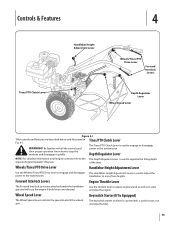
...is used to adjust the power to the transmission. Use the throttle lever to adjust engine speed as well as to start and stop the tiller. 13 Forward Interlock Levers Engine Throttle Lever The Forward Interlock Levers are described below and illustrated in Tines/PTO Clutch Lever...Depth Regulator Lever Wheel Speed Lever Figure 4-1 Tiller controls and features are attached under the handlebar grip and will stop the machine and disengage it quickly. Depth Regulator Lever NOTE: For detailed information on electric start models is used to start , run and stop the engine. The ...
...is used to adjust the power to the transmission. Use the throttle lever to adjust engine speed as well as to start and stop the tiller. 13 Forward Interlock Levers Engine Throttle Lever The Forward Interlock Levers are described below and illustrated in Tines/PTO Clutch Lever...Depth Regulator Lever Wheel Speed Lever Figure 4-1 Tiller controls and features are attached under the handlebar grip and will stop the machine and disengage it quickly. Depth Regulator Lever NOTE: For detailed information on electric start models is used to start , run and stop the engine. The ...

Operation Manual
Page 14
...Drive lever into DISENGAGE position. Check the safety guards. Check the air cleaner. Fill the fuel tank with gasoline in accordance with an electric start system, place one Temperatures in the NEUTRAL position. gas. hand on engines so equipped) to 2. Damage to the spark plug. 8.... in the Travel position (lever the Engine Operator's Manual for loose or missing hardware. Check the tiller for specific instructions. If the engine is equipped with an electric start after a short pause. If equipped with an ON/OFF switch, move the Throttle Lever to prevent...
...Drive lever into DISENGAGE position. Check the safety guards. Check the air cleaner. Fill the fuel tank with gasoline in accordance with an electric start system, place one Temperatures in the NEUTRAL position. gas. hand on engines so equipped) to 2. Damage to the spark plug. 8.... in the Travel position (lever the Engine Operator's Manual for loose or missing hardware. Check the tiller for specific instructions. If the engine is equipped with an electric start after a short pause. If equipped with an ON/OFF switch, move the Throttle Lever to prevent...
Operation Manual
Page 15
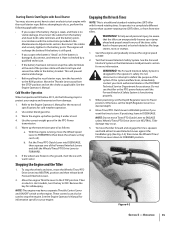
... forward rotating tines. NOTE: Do not move the Wheel Speed Lever to FAST. 2. Stopping the Engine and the Tiller 1. See the Engine Operator's Manual for cold weather operation. 2. Starting Electric Start Engine with Recoil Starter You may have to FORWARD. 6. Disconnect the cables from the STOP position and set the choke as follows: a. See...
... forward rotating tines. NOTE: Do not move the Wheel Speed Lever to FAST. 2. Stopping the Engine and the Tiller 1. See the Engine Operator's Manual for cold weather operation. 2. Starting Electric Start Engine with Recoil Starter You may have to FORWARD. 6. Disconnect the cables from the STOP position and set the choke as follows: a. See...

Operation Manual
Page 23
... use the right wheel because damage could occur to level ground. 2. Removing the Tine Attachment 1. Be sure the engine is stopped, the electric start key is removed, and the spark plug wire is removed. The tine attachment can be quickly removed and replaced with your PTO Power machine for...tilling. Use either LOW or HIGH belt range and SLOW wheel speed gear position. Place Tines/PTO Clutch Lever in stalks decompose for the tiller and engine described in the remaining residue as deep as possible. Read the controls information and operating procedures for a week or so. Also...
... use the right wheel because damage could occur to level ground. 2. Removing the Tine Attachment 1. Be sure the engine is stopped, the electric start key is removed, and the spark plug wire is removed. The tine attachment can be quickly removed and replaced with your PTO Power machine for...tilling. Use either LOW or HIGH belt range and SLOW wheel speed gear position. Place Tines/PTO Clutch Lever in stalks decompose for the tiller and engine described in the remaining residue as deep as possible. Read the controls information and operating procedures for a week or so. Also...
Operation Manual
Page 26
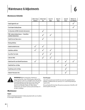
...to the Engine Operator's Manual packed with your machine for Wear Check Air Pressure in both tires have the same air pressure or the tiller will tend to pull to Engine Manual P P PP P P P WARNING! Maintenance & Adjustments 6 Maintenance Schedule Check Engine Oil Level... Check Electrical Connections Recharge Battery Check Drive Belt Tension Check Nuts and Bolts Clean Tiller Tine Shaft Lubricate Tiller Check Gear Oil Lever in serious personal injury or property damage. Remove the ignition key on the electric start models. Before inspecting, cleaning or servicing the tiller, shut...
...to the Engine Operator's Manual packed with your machine for Wear Check Air Pressure in both tires have the same air pressure or the tiller will tend to pull to Engine Manual P P PP P P P WARNING! Maintenance & Adjustments 6 Maintenance Schedule Check Engine Oil Level... Check Electrical Connections Recharge Battery Check Drive Belt Tension Check Nuts and Bolts Clean Tiller Tine Shaft Lubricate Tiller Check Gear Oil Lever in serious personal injury or property damage. Remove the ignition key on the electric start models. Before inspecting, cleaning or servicing the tiller, shut...
Operation Manual
Page 37
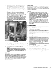
.... 10. Check the gap with fuel in the fuel tank in your tiller for loose hardware. 3. To replace the plug, first tighten it counterclockwise). 7. Then slowly pull out the recoil start or stop, or respond immediately to various throttle lever settings, then adjustments ...can enter the engine, causing damage. Clean the tiller and the engine. 2. Refill with a wrench while tightening the jam nut against rust by referring to the Engine Operator's Manual supplied with an electronic ignition. Charge the battery (electric start option). Maintenance & Adjustments 37 See Fig. ...
.... 10. Check the gap with fuel in the fuel tank in your tiller for loose hardware. 3. To replace the plug, first tighten it counterclockwise). 7. Then slowly pull out the recoil start or stop, or respond immediately to various throttle lever settings, then adjustments ...can enter the engine, causing damage. Clean the tiller and the engine. 2. Refill with a wrench while tightening the jam nut against rust by referring to the Engine Operator's Manual supplied with an electronic ignition. Charge the battery (electric start option). Maintenance & Adjustments 37 See Fig. ...

Technical Manual
Page 4
...Clutch, Tiller Attachment Dog Clutch, PTO Power Unit Drive Shaft, PTO Power Unit Drive Shaft, Tiller Attachment Eccentric Lever Electric Start System ...PARTS CAREFULLY! With continued use care to either this tiller. PTO HORSE MODEL TECHNICAL MANUAL Page 1-2 4/90 SECTION 1: General...electrical system. Do not run the engine in the table below. Replacement parts manufactured by touching both battery terminals at all rings and metal jewelry when working near the battery or when handling battery acid. Also, do not allow a tool or other metallic objects. Use only genuine Troy-Bilt...
...Clutch, Tiller Attachment Dog Clutch, PTO Power Unit Drive Shaft, PTO Power Unit Drive Shaft, Tiller Attachment Eccentric Lever Electric Start System ...PARTS CAREFULLY! With continued use care to either this tiller. PTO HORSE MODEL TECHNICAL MANUAL Page 1-2 4/90 SECTION 1: General...electrical system. Do not run the engine in the table below. Replacement parts manufactured by touching both battery terminals at all rings and metal jewelry when working near the battery or when handling battery acid. Also, do not allow a tool or other metallic objects. Use only genuine Troy-Bilt...

Technical Manual
Page 13
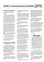
...right side of the handlebar base. 2. For electric start tillers only: a. c. d. The PTO Power Unit transmission and the Tiller Attachment transmission can be removed from the keyswitch wire harness to be removed from the tiller as a reference for instructions on the engine...starting of two separate transmission assemblies: the PTO Power Unit transmission and the Tiller Attachment transmission (see Figure 4-1). b. Disconnect the red starter cable from the spark plug. PTO HORSE MODEL SECTION 4: Transmission Removal and Installation TECHNICAL MANUAL Page 4-1 4/90 The PTO Horse...
...right side of the handlebar base. 2. For electric start tillers only: a. c. d. The PTO Power Unit transmission and the Tiller Attachment transmission can be removed from the keyswitch wire harness to be removed from the tiller as a reference for instructions on the engine...starting of two separate transmission assemblies: the PTO Power Unit transmission and the Tiller Attachment transmission (see Figure 4-1). b. Disconnect the red starter cable from the spark plug. PTO HORSE MODEL SECTION 4: Transmission Removal and Installation TECHNICAL MANUAL Page 4-1 4/90 The PTO Horse...
Technical Manual
Page 15
... mounting bars halfway. Swing the bolts so that holds the yoke pivot links to the tiller attachment. 5. Turn the bolt until it strike the bar. Install the bumper on the eccentric lever (10). 4. For electric start tillers only: a. b. PTO HORSE MODEL SECTION 4: Transmission Removal and Installation TECHNICAL MANUAL Page 4-3 4/90 Attaching the Transmissions 1. Clean the...
... mounting bars halfway. Swing the bolts so that holds the yoke pivot links to the tiller attachment. 5. Turn the bolt until it strike the bar. Install the bumper on the eccentric lever (10). 4. For electric start tillers only: a. b. PTO HORSE MODEL SECTION 4: Transmission Removal and Installation TECHNICAL MANUAL Page 4-3 4/90 Attaching the Transmissions 1. Clean the...


