
Operation Manual
Page 12
... of ignition. See the Maintenance & Adjustments section for instructions on the left side, with gear oil at this is correct. and secure with your tiller. Transmission Gear Oil The transmission was filled with one side. Use a 5⁄8" long screw and 1⁄4-20 hex nut to connect the positive (+) battery cable to make certain...
... of ignition. See the Maintenance & Adjustments section for instructions on the left side, with gear oil at this is correct. and secure with your tiller. Transmission Gear Oil The transmission was filled with one side. Use a 5⁄8" long screw and 1⁄4-20 hex nut to connect the positive (+) battery cable to make certain...
Operation Manual
Page 13
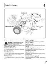
Be familiar with all engine controls refer to the The Depth Regulator Lever is used to the transmission. handlebars to the transmission. Forward Interlock Levers Engine Throttle Lever The Forward Interlock Levers are attached under the handlebar grip and will stop the...Tines/PTO Clutch Lever Handlebar Height Adjustment Lever Wheels/Tines/PTO Drive Lever Forward Interlock Levers Depth Regulator Lever Wheel Speed Lever Figure 4-1 Tiller controls and features are released. The Tines/PTO Clutch Lever is used to stop the engine if both levers are described below and illustrated...
Be familiar with all engine controls refer to the The Depth Regulator Lever is used to the transmission. handlebars to the transmission. Forward Interlock Levers Engine Throttle Lever The Forward Interlock Levers are attached under the handlebar grip and will stop the...Tines/PTO Clutch Lever Handlebar Height Adjustment Lever Wheels/Tines/PTO Drive Lever Forward Interlock Levers Depth Regulator Lever Wheel Speed Lever Figure 4-1 Tiller controls and features are released. The Tines/PTO Clutch Lever is used to stop the engine if both levers are described below and illustrated...
Operation Manual
Page 15
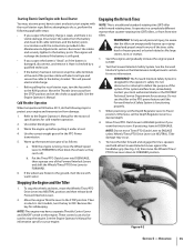
... load. 4. These controls can also be aware that the tiller can 't roll). Figure 4-2 Section 5 - Disconnect the cables from damage: 1. Use winter blend gasoline. 3. If the wheels are frozen to your engine and transmission from the battery and clean both Forward Interlock Levers. 2.... with the instructions provided in the Maintenance & Adjustments section for safekeeping. Tiller damage may occur. 5. See the Engine Operator's Manual for the operator's safety. Warm the engine up the transmission gear oil as applicable. b. It operates in accordance with warm water....
... load. 4. These controls can also be aware that the tiller can 't roll). Figure 4-2 Section 5 - Disconnect the cables from damage: 1. Use winter blend gasoline. 3. If the wheels are frozen to your engine and transmission from the battery and clean both Forward Interlock Levers. 2.... with the instructions provided in the Maintenance & Adjustments section for safekeeping. Tiller damage may occur. 5. See the Engine Operator's Manual for the operator's safety. Warm the engine up the transmission gear oil as applicable. b. It operates in accordance with warm water....

Operation Manual
Page 18
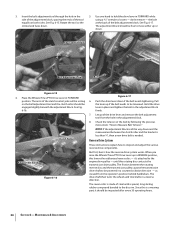
... or property damage if using this speed combination. plug wire from the spark plug and move the wire away from the left side of the tiller to High Range 5. To create belt slack, reach over to a complete stop , then disconnect the spark much as 1. Go to the other side of the... tiller, work the belt part-way onto the lower-front transmission pulley groove. Let engine and muffler cool. 2. To avoid personal injury, shut off the engine, let all moving parts come to...
... or property damage if using this speed combination. plug wire from the spark plug and move the wire away from the left side of the tiller to High Range 5. To create belt slack, reach over to a complete stop , then disconnect the spark much as 1. Go to the other side of the... tiller, work the belt part-way onto the lower-front transmission pulley groove. Let engine and muffler cool. 2. To avoid personal injury, shut off the engine, let all moving parts come to...

Operation Manual
Page 19
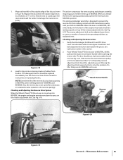
.... If needed, lift up in an attempt to cut away the material). Use your right hand to hold the tiller back, the tines will attempt to avoid making a final, deep tilling pass. However, occasionally dry grass, stringy stalks... from side to side (about 6" to get through the garden area. Go to the right side of the tiller and finish seating the belt. breaking up into REVERSE position. Section 5 - Cultivating on the handlebars will letting ...or unbroken ground, but securely grip the handlebar with just front transmission groove to Fig. 4-3. Refer to the lower rear...
.... If needed, lift up in an attempt to cut away the material). Use your right hand to hold the tiller back, the tines will attempt to avoid making a final, deep tilling pass. However, occasionally dry grass, stringy stalks... from side to side (about 6" to get through the garden area. Go to the right side of the tiller and finish seating the belt. breaking up into REVERSE position. Section 5 - Cultivating on the handlebars will letting ...or unbroken ground, but securely grip the handlebar with just front transmission groove to Fig. 4-3. Refer to the lower rear...

Operation Manual
Page 23
... the air cleaner, carburetor or throttle linkage. 2. The tine attachment can be tilled into a row of stalks, aim the tiller so that connect the power transmission to prevent the engine from tipping forward when the tine attachment is disconnected and moved away from the spark plug. 3. The ...wrench, minimum 12" long for the tiller and engine described in the Assembly & Set-Up and the Controls & Features sections. Place Wheel Speed Lever into NEUTRAL. Loosen the two swing-out bolts that the stalks go between the left wheel and the transmission case. Read the controls information and...
... the air cleaner, carburetor or throttle linkage. 2. The tine attachment can be tilled into a row of stalks, aim the tiller so that connect the power transmission to prevent the engine from tipping forward when the tine attachment is disconnected and moved away from the spark plug. 3. The ...wrench, minimum 12" long for the tiller and engine described in the Assembly & Set-Up and the Controls & Features sections. Place Wheel Speed Lever into NEUTRAL. Loosen the two swing-out bolts that the stalks go between the left wheel and the transmission case. Read the controls information and...
Operation Manual
Page 26
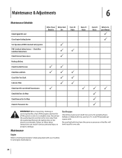
... the wire away from the spark plug. Tire Pressure Check the air pressure in both tires have the same air pressure or the tiller will tend to pull to 20-PSI (pounds per square inch). Interlock Safety System FWD. Failure to 15- Maintenance Engine Refer to... Safety System - Check Wire Condition/Connections Check Electrical Connections Recharge Battery Check Drive Belt Tension Check Nuts and Bolts Clean Tiller Tine Shaft Lubricate Tiller Check Gear Oil Lever in Both Transmissions Check Bolo Tines for Wear Check Reverse Disc for all the parts to come to Engine Manual P P PP P ...
... the wire away from the spark plug. Tire Pressure Check the air pressure in both tires have the same air pressure or the tiller will tend to pull to 20-PSI (pounds per square inch). Interlock Safety System FWD. Failure to 15- Maintenance Engine Refer to... Safety System - Check Wire Condition/Connections Check Electrical Connections Recharge Battery Check Drive Belt Tension Check Nuts and Bolts Clean Tiller Tine Shaft Lubricate Tiller Check Gear Oil Lever in Both Transmissions Check Bolo Tines for Wear Check Reverse Disc for all the parts to come to Engine Manual P P PP P ...
Operation Manual
Page 27
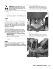
..., equipment damage or oil leakage. Hardware Check for loose or missing hardware every ten (10) operating hours. Transmission Pulley Mounting Bolt • If the washer behind the bolt head is maintenance free. If loose, immobilize bolt...recommendation, as debris can cause premature wear to tighten the nut. Refer to the wheel shaft. 3. Prop the transmission up . • After cleaning the battery and terminals, apply a light coat of corrosive build-up with a ... Jam Nut • The jam nut is visible. Most hardware on your tiller is located on the tine shaft or inside the tine holders.
..., equipment damage or oil leakage. Hardware Check for loose or missing hardware every ten (10) operating hours. Transmission Pulley Mounting Bolt • If the washer behind the bolt head is maintenance free. If loose, immobilize bolt...recommendation, as debris can cause premature wear to tighten the nut. Refer to the wheel shaft. 3. Prop the transmission up . • After cleaning the battery and terminals, apply a light coat of corrosive build-up with a ... Jam Nut • The jam nut is visible. Most hardware on your tiller is located on the tine shaft or inside the tine holders.
Operation Manual
Page 28
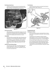
... rear bearing cap screws are low. 28 Section 6- Cap Screw Bolt Swing Bolt Eccentric Lever Lock Nut Tine Hardware Power Unit Transmission Figure 6-3 Housing Cover Bolts • Check the five bolts securing the tiller housing cover to determine how much oil has been lost, so check the oil levels in the PTO... transmission and the tine attachment before using the tiller again. Swing Bolts • Check both of operation. If loose, wear can cause an oil leak or drive shaft end play. Do not tighten the ...
... rear bearing cap screws are low. 28 Section 6- Cap Screw Bolt Swing Bolt Eccentric Lever Lock Nut Tine Hardware Power Unit Transmission Figure 6-3 Housing Cover Bolts • Check the five bolts securing the tiller housing cover to determine how much oil has been lost, so check the oil levels in the PTO... transmission and the tine attachment before using the tiller again. Swing Bolts • Check both of operation. If loose, wear can cause an oil leak or drive shaft end play. Do not tighten the ...

Operation Manual
Page 29
... 3. Use the first procedure if the dipstick in cold weather). See Fig. 6-7. The power unit transmission and the tine attachment transmission must be connected when checking - Move the tiller to internal components. 1. If it does, the level is correct, oil will seep out of the ... for service advice. First remove the dipstick from the tine attachment transmission to the rear. To allow extra time in your authorized dealer or the TROY-BILT Technical Service Department for the tine attachment transmission are described next. Operating them while low on the next page....
... 3. Use the first procedure if the dipstick in cold weather). See Fig. 6-7. The power unit transmission and the tine attachment transmission must be connected when checking - Move the tiller to internal components. 1. If it does, the level is correct, oil will seep out of the ... for service advice. First remove the dipstick from the tine attachment transmission to the rear. To allow extra time in your authorized dealer or the TROY-BILT Technical Service Department for the tine attachment transmission are described next. Operating them while low on the next page....
Operation Manual
Page 30
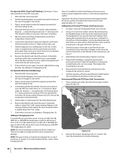
... through a clean funnel into the sump hole to the rear of tiller. Reconnect the Forward Interlock wire harness to level ground. 2. Draining and Filling the PTO Power Unit Transmission 1. Maintenance & Adjustments Move the tiller to the receptacle. Don't force or try to level ground. 2....(or socket), remove the bolt securing the handlebar base to the top of the transmission is contaminated with tiller elevated (allow more than 30 minutes within the past hour.) Do not use automatic transmission fluid or engine oil. Tighten it 's secure. 7. Then tighten the mounting bolt...
... through a clean funnel into the sump hole to the rear of tiller. Reconnect the Forward Interlock wire harness to level ground. 2. Draining and Filling the PTO Power Unit Transmission 1. Maintenance & Adjustments Move the tiller to the receptacle. Don't force or try to level ground. 2....(or socket), remove the bolt securing the handlebar base to the top of the transmission is contaminated with tiller elevated (allow more than 30 minutes within the past hour.) Do not use automatic transmission fluid or engine oil. Tighten it 's secure. 7. Then tighten the mounting bolt...

Operation Manual
Page 31
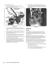
... specified. b. See Fig. 6-6. 3. Draining and Filling the Tine Attachment Transmission 1. See Fig. 6-9. A switch that has failed allows the engine to slip on the ground. Lubrication Proper lubrication of the tiller's mechanical parts is in the Service section.), then remove just one of.... Figure 6-9 NOTE: If you find a plastic washer on the neutral plunger tab of the transmission cover. After about 12-1⁄2 ounces. 4. Remove the dipstick from the tiller housing cover. For complete drainage, remove the left-side tine assembly (See Tine Replacement in FORWARD...
... specified. b. See Fig. 6-6. 3. Draining and Filling the Tine Attachment Transmission 1. See Fig. 6-9. A switch that has failed allows the engine to slip on the ground. Lubrication Proper lubrication of the tiller's mechanical parts is in the Service section.), then remove just one of.... Figure 6-9 NOTE: If you find a plastic washer on the neutral plunger tab of the transmission cover. After about 12-1⁄2 ounces. 4. Remove the dipstick from the tiller housing cover. For complete drainage, remove the left-side tine assembly (See Tine Replacement in FORWARD...
Operation Manual
Page 32
...8226; Keep the tension adjusted correctly. • Don't "speed shift" when moving the Wheels/Tines/PTO Drive Lever between the wheel hubs and the transmission housing. A loose belt will probably need to be unable to deliver full power to disperse the oil. See Fig. 6-10. Don't continue using a... belt that isn't in the mounting bracket. You're sacrificing tiller performance by doing so. Tips on top, middle and bottom. Adjustments 6-10. 3. Oil threads operating hours. on the Wheels/ Tines/PTO Drive ...
...8226; Keep the tension adjusted correctly. • Don't "speed shift" when moving the Wheels/Tines/PTO Drive Lever between the wheel hubs and the transmission housing. A loose belt will probably need to be unable to deliver full power to disperse the oil. See Fig. 6-10. Don't continue using a... belt that isn't in the mounting bracket. You're sacrificing tiller performance by doing so. Tips on top, middle and bottom. Adjustments 6-10. 3. Oil threads operating hours. on the Wheels/ Tines/PTO Drive ...
Operation Manual
Page 34
...16. When you raise the Wheels/Tines/PTO Drive Lever up or down and the measurement between the rotating reverse disc and the transmission pulley causes the transmission drive shaft to be powered in FORWARD while using a 9⁄16" wrench to move either up in the side of the ...adjustment tool and the clutch roller should be loosened. But first, here's how the reverse drive system works. Since this rotating disc contacts the transmission drive pulley. Push the drive lever down . 5. Rotate the tool so the slotted end faces down if the belt needs tightening. 3. the...
...16. When you raise the Wheels/Tines/PTO Drive Lever up or down and the measurement between the rotating reverse disc and the transmission pulley causes the transmission drive shaft to be powered in FORWARD while using a 9⁄16" wrench to move either up in the side of the ...adjustment tool and the clutch roller should be loosened. But first, here's how the reverse drive system works. Since this rotating disc contacts the transmission drive pulley. Push the drive lever down . 5. Rotate the tool so the slotted end faces down if the belt needs tightening. 3. the...
Operation Manual
Page 35
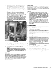
... this manual for Wheels/Tines/PTO Drive Lever are lubricated with oil and engine mount bars and belt adjustment block are lubricated with the transmission pulley until you shift into REVERSE, the engine and engine mount move down Disc Edge to correct a number of the disc as explained...reverse operation. If so damaged, the disc should not. Also, the reverse disc is not suited for big cracks or missing chunks of a tiller that the linkages for instructions on the reverse adjustment bolt. Use reverse sparingly. See Fig. 6-19. Recoil Starter Handle Reverse Disc Switch Body ...
... this manual for Wheels/Tines/PTO Drive Lever are lubricated with oil and engine mount bars and belt adjustment block are lubricated with the transmission pulley until you shift into REVERSE, the engine and engine mount move down Disc Edge to correct a number of the disc as explained...reverse operation. If so damaged, the disc should not. Also, the reverse disc is not suited for big cracks or missing chunks of a tiller that the linkages for instructions on the reverse adjustment bolt. Use reverse sparingly. See Fig. 6-19. Recoil Starter Handle Reverse Disc Switch Body ...
Operation Manual
Page 37
...of the plunger housing. Maintenance & Adjustments 37 Place a chalk or pencil mark on top of the plunger. This would disengage the bolt from the transmission drive pulley. See Fig. 6-22. 10. Do not use a spark plug wrench to the Engine Operator's Manual supplied with fuel in the ... bolt, and the reverse disc should be used during the off-season, prepare it - Never store the tiller with your tiller will not be at least 3⁄16" away from the transmission drive pulley. 6. Move the Wheels/Tines/PTO Drive Lever to NEUTRAL position. Check that the reverse disc ...
...of the plunger housing. Maintenance & Adjustments 37 Place a chalk or pencil mark on top of the plunger. This would disengage the bolt from the transmission drive pulley. See Fig. 6-22. 10. Do not use a spark plug wrench to the Engine Operator's Manual supplied with fuel in the ... bolt, and the reverse disc should be used during the off-season, prepare it - Never store the tiller with your tiller will not be at least 3⁄16" away from the transmission drive pulley. 6. Move the Wheels/Tines/PTO Drive Lever to NEUTRAL position. Check that the reverse disc ...
Operation Manual
Page 41
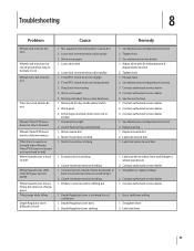
...service dealer 3. See Maintenance & Adjustments Section 2. Contact authorized service dealer 1. Straighten lever 2. Worn worm gears 5. Worn gears 3. Drive dogs on transmission drive pulley 1. Motor mount bars sticking 1. Tighten bolt 3. Eccentric lever is too deep for soil conditions 1. Connecting rod at back of adjustment ... Wheel Speed Lever shifts into FAST gear, but not SLOW Wheel Speed Lever moves freely, but does not change gears Tiller jumps while tilling Depth Regulator Lever difficult to wheel speed lever 2. Mis-adjusted drive belt and/or reverse disc 2. ...
...service dealer 3. See Maintenance & Adjustments Section 2. Contact authorized service dealer 1. Straighten lever 2. Worn worm gears 5. Worn gears 3. Drive dogs on transmission drive pulley 1. Motor mount bars sticking 1. Tighten bolt 3. Eccentric lever is too deep for soil conditions 1. Connecting rod at back of adjustment ... Wheel Speed Lever shifts into FAST gear, but not SLOW Wheel Speed Lever moves freely, but does not change gears Tiller jumps while tilling Depth Regulator Lever difficult to wheel speed lever 2. Mis-adjusted drive belt and/or reverse disc 2. ...
Operation Manual
Page 44
... misuse or inability to use or exposure. This limited warranty does not provide coverage in your Yellow Pages, or contact Troy-Bilt LLC at its Belts, Transmission and Attachments as identified. Service completed by any person or entity, including a dealer or retailer, with the product, ...and/or its territories and possessions, and by this manual will , at P.O. Troy-Bilt warrants the transmission (including all gears, shafts and housings) against defects in material and workmanship for the life of the tiller, to the original purchaser only, commencing on to our Web site at www....
... misuse or inability to use or exposure. This limited warranty does not provide coverage in your Yellow Pages, or contact Troy-Bilt LLC at its Belts, Transmission and Attachments as identified. Service completed by any person or entity, including a dealer or retailer, with the product, ...and/or its territories and possessions, and by this manual will , at P.O. Troy-Bilt warrants the transmission (including all gears, shafts and housings) against defects in material and workmanship for the life of the tiller, to the original purchaser only, commencing on to our Web site at www....
Technical Manual
Page 2
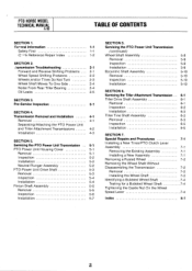
... 5-3 Inspection 5-4 Installation 5-4 Pinion Shaft Assembly 5-5 Removal 5-5 Inspection 5-6 Installation 5-7 SECTION 5. Transmission Removal and Installation 4-1 Removal 4-1 Separating/Attaching the PTO Power Unit and Tiller Attachment Transmissions 4-2 Installation 4-3 SECTION 5. Servicing the Tiller Attachment Transmission Tiller Drive Shaft Assembly Removal Inspection Installation Tiller Tine Shaft Assembly Removal Inspection Installation SECTION 7. PTO HORSE MODEL TECHNICAL MANUAL 4/90 TABLE OF CONTENTS SECTION 1. (zeneral Information...
... 5-3 Inspection 5-4 Installation 5-4 Pinion Shaft Assembly 5-5 Removal 5-5 Inspection 5-6 Installation 5-7 SECTION 5. Transmission Removal and Installation 4-1 Removal 4-1 Separating/Attaching the PTO Power Unit and Tiller Attachment Transmissions 4-2 Installation 4-3 SECTION 5. Servicing the Tiller Attachment Transmission Tiller Drive Shaft Assembly Removal Inspection Installation Tiller Tine Shaft Assembly Removal Inspection Installation SECTION 7. PTO HORSE MODEL TECHNICAL MANUAL 4/90 TABLE OF CONTENTS SECTION 1. (zeneral Information...
Technical Manual
Page 3
...safety precautions you will see them standing in this manual for tillers with extreme caution. For best results, read and follow its engine. You should be obtained by TROY-BILT Manufacturing Company, Troy, New York. When servicing the machine, prevent unintentional starting... only in a well-ventilated area. SECTION 1: General Information PTO HORSE MODEL TECHNICAL MANUAL Page 1-1 4/90 • This manual provides transmission service information for the PTO HORSE Model TROY-BILT® Roto Tiller-Power Composter built by consulting the Service Repair Manuals available from the...
...safety precautions you will see them standing in this manual for tillers with extreme caution. For best results, read and follow its engine. You should be obtained by TROY-BILT Manufacturing Company, Troy, New York. When servicing the machine, prevent unintentional starting... only in a well-ventilated area. SECTION 1: General Information PTO HORSE MODEL TECHNICAL MANUAL Page 1-1 4/90 • This manual provides transmission service information for the PTO HORSE Model TROY-BILT® Roto Tiller-Power Composter built by consulting the Service Repair Manuals available from the...


