
Operation Manual
Page 27
...operating hours. This immobilizes the pulley while you tighten the bolt. Tine Shaft After every 10 operating hours, remove the left side of petroleum jelly or grease to the wheel shaft before re-installing the wheels. After cleaning away any debris and removing old grease, apply fresh ...that have accumulated on the wheel shaft Please follow this maintenance recommendation, as debris can cause premature wear to raise the wheels off the ground. 2. Transmission Pulley Mounting Bolt • If the washer behind the bolt head is located on your tiller is maintenance free. See Fig...
...operating hours. This immobilizes the pulley while you tighten the bolt. Tine Shaft After every 10 operating hours, remove the left side of petroleum jelly or grease to the wheel shaft before re-installing the wheels. After cleaning away any debris and removing old grease, apply fresh ...that have accumulated on the wheel shaft Please follow this maintenance recommendation, as debris can cause premature wear to raise the wheels off the ground. 2. Transmission Pulley Mounting Bolt • If the washer behind the bolt head is located on your tiller is maintenance free. See Fig...
Operation Manual
Page 32
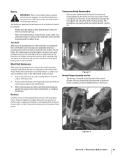
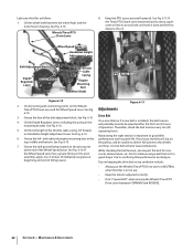
... oil into its access hole, and work it back and forth to good tiller 6. Wheel Speed Lever Handlebar Height Adjustment Lever Belt Adjustment Block Depth Regulator Lever Grease Fitting Throttle Cable Casing Engine Mounting Bars Wheel Shaft PTO Access Area Figure 6-10 Figure 6-11 2. See Fig. 6-10. ...for cuts, cracks, deterioration, etc. See Fig. 6-10. Grease the face of the Wheel Speed Lever. Lubricate the tiller as follows: 1. See Fig. 6-11. Maintaining the right tension is installed), the belt tension will probably need to be unable to deliver full power to -3 strokes ...
... oil into its access hole, and work it back and forth to good tiller 6. Wheel Speed Lever Handlebar Height Adjustment Lever Belt Adjustment Block Depth Regulator Lever Grease Fitting Throttle Cable Casing Engine Mounting Bars Wheel Shaft PTO Access Area Figure 6-10 Figure 6-11 2. See Fig. 6-10. ...for cuts, cracks, deterioration, etc. See Fig. 6-10. Grease the face of the Wheel Speed Lever. Lubricate the tiller as follows: 1. See Fig. 6-11. Maintaining the right tension is installed), the belt tension will probably need to be unable to deliver full power to -3 strokes ...
Operation Manual
Page 40
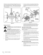
... on the hardware if it up with a metal tool. Move the Wheels/Tines/PTO Drive Lever to NEUTRAL, the Wheel Speed Lever to either FAST or SLOW position, and the Tines/PTO Clutch Lever to the tine shaft. Gently tilt the tiller forward until the engine rests on left -side and right-side holders... . When the holder is off, clean all dirt and debris from cuts or scrapes. The tines or tine hooded edges may be installed in Single Tine Replacement above the tine shaft.) Replace the bolts and nuts and tighten them L and R. 3. Here's how to the tine holder plate. If badly worn, they ...
... on the hardware if it up with a metal tool. Move the Wheels/Tines/PTO Drive Lever to NEUTRAL, the Wheel Speed Lever to either FAST or SLOW position, and the Tines/PTO Clutch Lever to the tine shaft. Gently tilt the tiller forward until the engine rests on left -side and right-side holders... . When the holder is off, clean all dirt and debris from cuts or scrapes. The tines or tine hooded edges may be installed in Single Tine Replacement above the tine shaft.) Replace the bolts and nuts and tighten them L and R. 3. Here's how to the tine holder plate. If badly worn, they ...
Technical Manual
Page 2
... 4-1 Separating/Attaching the PTO Power Unit and Tiller Attachment Transmissions 4-2 Installation 4-3 SECTION 5. PTO HORSE MODEL TECHNICAL MANUAL 4/90 TABLE OF CONTENTS SECTION 1. (zeneral Information 1-1 Safety First 1-1 C- 4-k Reference Repair Index 1-2 SECTION 2. .'ransmission Troubleshooting 2-1 Forward and Reverse Shifting Problems 2-1 Wheel Speed Shifting Problems 2-2 Wheels and/or Tines Do Not Turn 2-3 Wheel Shaft Moves To One Side 2-4 Noise From Rear...
... 4-1 Separating/Attaching the PTO Power Unit and Tiller Attachment Transmissions 4-2 Installation 4-3 SECTION 5. PTO HORSE MODEL TECHNICAL MANUAL 4/90 TABLE OF CONTENTS SECTION 1. (zeneral Information 1-1 Safety First 1-1 C- 4-k Reference Repair Index 1-2 SECTION 2. .'ransmission Troubleshooting 2-1 Forward and Reverse Shifting Problems 2-1 Wheel Speed Shifting Problems 2-2 Wheels and/or Tines Do Not Turn 2-3 Wheel Shaft Moves To One Side 2-4 Noise From Rear...
Technical Manual
Page 7
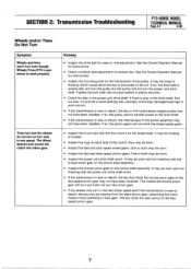
...One or both may not have been installed. It may not have been installed. If so, the pulley cannot transfer power to fall out. Tines turn but it will not turn the wheel shaft. See the Owner/Operator Manual for play in the drive shaft, find out why. The key locks... the stem pinion gear, preventing the transmission from operating in slow gear. SECTION 2: Transmission Troubleshooting PTO HORSE MODEL TECHNICAL MANUAL Page 2-3 4/90 Wheels and/or Tines Do Not Turn Symptom Wheels and tines won't turn only in one speed. One or both may be missing or broken. •...
...One or both may not have been installed. It may not have been installed. If so, the pulley cannot transfer power to fall out. Tines turn but it will not turn the wheel shaft. See the Owner/Operator Manual for play in the drive shaft, find out why. The key locks... the stem pinion gear, preventing the transmission from operating in slow gear. SECTION 2: Transmission Troubleshooting PTO HORSE MODEL TECHNICAL MANUAL Page 2-3 4/90 Wheels and/or Tines Do Not Turn Symptom Wheels and tines won't turn only in one speed. One or both may be missing or broken. •...
Technical Manual
Page 9
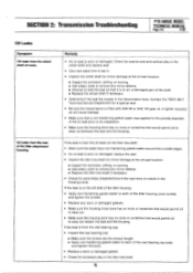
... prior to its installation. • Make sure the housing bore has no nicks or scratches that would permit oil to seep out. • Make sure the housing bore has no nicks or scratches that wou►d permit oil to each of the shaft. ■ Replace the wheel shaft if necessary. •... in the tiller tine shaft. Check for a special seal. • Be sure the transmission is worn or damaged. If the leak is on the left side of the tiller housing: • Apply non-hardening gasket sealer to seep out beteen the seal and the housing. Contact the TROY-BILT Technical Service ...
... prior to its installation. • Make sure the housing bore has no nicks or scratches that would permit oil to seep out. • Make sure the housing bore has no nicks or scratches that wou►d permit oil to each of the shaft. ■ Replace the wheel shaft if necessary. •... in the tiller tine shaft. Check for a special seal. • Be sure the transmission is worn or damaged. If the leak is on the left side of the tiller housing: • Apply non-hardening gasket sealer to seep out beteen the seal and the housing. Contact the TROY-BILT Technical Service ...

Technical Manual
Page 13
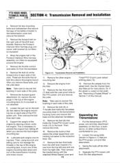
... SECTION 4: Transmission Removal and Installation TECHNICAL MANUAL Page 4-1 4/90 The PTO Horse Model transmission consists of the handlebar base. 2. Disconnect the red starter cable from the tiller as described in this section. PTO POWER UNIT ( • •~ DOG CLUTCH/POWER UNIT 4I TRANSMISSION PULLEY DOG CLUTCH/TILLER ATTACHMENT TILLER ATTACHMENT SWINGBOLTS WHEEL SHAFT TINES/PTO CLUTCH LEVER...
... SECTION 4: Transmission Removal and Installation TECHNICAL MANUAL Page 4-1 4/90 The PTO Horse Model transmission consists of the handlebar base. 2. Disconnect the red starter cable from the tiller as described in this section. PTO POWER UNIT ( • •~ DOG CLUTCH/POWER UNIT 4I TRANSMISSION PULLEY DOG CLUTCH/TILLER ATTACHMENT TILLER ATTACHMENT SWINGBOLTS WHEEL SHAFT TINES/PTO CLUTCH LEVER...
Technical Manual
Page 14
... that join the PTO power unit and tiller attachment. 3. Or, if the wheel is necessary to the eccentric lever (10). 17. These are the bolts that retains the wheel speed lever connecting rod swivel to prevent the engine from the wheel shaft. Remove the other surface that is not... base to recover the bushing in Section 7 of the engine by placing a block under the engine. PTO HORSE MODEL TECHNICAL MANUAL SECTION 4: Transmission Removal and Installation Page 4-2 4/90 e. Lubricate both engine mounting bars. See the Owner/Operator Manual for you remove these bolts...
... that join the PTO power unit and tiller attachment. 3. Or, if the wheel is necessary to the eccentric lever (10). 17. These are the bolts that retains the wheel speed lever connecting rod swivel to prevent the engine from the wheel shaft. Remove the other surface that is not... base to recover the bushing in Section 7 of the engine by placing a block under the engine. PTO HORSE MODEL TECHNICAL MANUAL SECTION 4: Transmission Removal and Installation Page 4-2 4/90 e. Lubricate both engine mounting bars. See the Owner/Operator Manual for you remove these bolts...

Technical Manual
Page 16
... unit and the tiller attachment are able to slide the lever to this important control lever. 27. Make sure that holds the lever to the eccentric shaft. 23. Connect the recharging wire that secures the Tines/PTO Clutch Lever (13) to the shaft. e. A correctly installed lever will have ...to be fully engaged), slide the detent plate to the directions found in the Owner/Operator Manual. 21. Check the operation of the Wheels/Tines/PTO Lever by shifting it can go no further. PTO HORSE MODEL TECHNICAL MANUAL SECTION ...
... unit and the tiller attachment are able to slide the lever to this important control lever. 27. Make sure that holds the lever to the eccentric shaft. 23. Connect the recharging wire that secures the Tines/PTO Clutch Lever (13) to the shaft. e. A correctly installed lever will have ...to be fully engaged), slide the detent plate to the directions found in the Owner/Operator Manual. 21. Check the operation of the Wheels/Tines/PTO Lever by shifting it can go no further. PTO HORSE MODEL TECHNICAL MANUAL SECTION ...
Technical Manual
Page 23
... seats; Insert the stem pinion assembly in these instructions. 1. To test the other side. 10. SECTION 5: PTO Power Unit Transmission PTO HORSE MODEL TECHNICAL MANUAL Page 5-7 4/90 Note: Thoroughly degrease and clean all , replace the bearing with the edge facing the worm gear. Bearings... is facing towards the fast speed pinion gear. Dirt or debris will prevent the O-rings from the shaft. If the gear teeth are clean. See the wheel shaft installation instructions in the fast speed gear at all parts before inspection. Use #30 weight oil to the ...
... seats; Insert the stem pinion assembly in these instructions. 1. To test the other side. 10. SECTION 5: PTO Power Unit Transmission PTO HORSE MODEL TECHNICAL MANUAL Page 5-7 4/90 Note: Thoroughly degrease and clean all , replace the bearing with the edge facing the worm gear. Bearings... is facing towards the fast speed pinion gear. Dirt or debris will prevent the O-rings from the shaft. If the gear teeth are clean. See the wheel shaft installation instructions in the fast speed gear at all parts before inspection. Use #30 weight oil to the ...
Technical Manual
Page 24
... seated too deeply, remove it and insert one or more shims (4) until the holes are aligned. Install O-rings (3) on each plug (2). 19. Use #30 weight oil to remove the wheel shaft without disassembling the entire PTO power unit, see if the spirol holes in place when driving a plug... inward). 16. Install the spirol pins (1) on each side. 21. PTO HORSE MODEL TECHNICAL MANUAL Page 5-8 4/90 SECTION 5: PTO Power Unit ...
... seated too deeply, remove it and insert one or more shims (4) until the holes are aligned. Install O-rings (3) on each plug (2). 19. Use #30 weight oil to remove the wheel shaft without disassembling the entire PTO power unit, see if the spirol holes in place when driving a plug... inward). 16. Install the spirol pins (1) on each side. 21. PTO HORSE MODEL TECHNICAL MANUAL Page 5-8 4/90 SECTION 5: PTO Power Unit ...
Technical Manual
Page 25
... feel the key in the shaft begin to the wheel shaft. Before installing the wheel shaft: • Make sure the hi-pro key (14) is a trial and error procedure. If there is excessively worn, discard the wheel shaft. • Examine both ends of the wheel shaft for a Bubbled Wheel Shaft" in Section 7. SECTION 5: PTO Power Unit Transmission PTO HORSE MODEL TECHNICAL MANUAL Page...
... feel the key in the shaft begin to the wheel shaft. Before installing the wheel shaft: • Make sure the hi-pro key (14) is a trial and error procedure. If there is excessively worn, discard the wheel shaft. • Examine both ends of the wheel shaft for a Bubbled Wheel Shaft" in Section 7. SECTION 5: PTO Power Unit Transmission PTO HORSE MODEL TECHNICAL MANUAL Page...
Technical Manual
Page 26
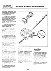
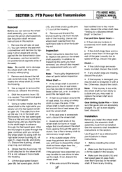
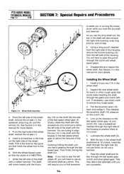
...housing. Vertical or diagonal play . Removal 1. Turn the housing upside down on the wheel shaft on both ends of wood from the eccentric lever and check to service the eccentric shaft assembly. PTO HORSE MODEL TECHNICAL MANUAL Page 5-10 4/90 SECTION 5: PTO Power Unit Transmission check for burrs... hammer and driver, and making sure the oil pick-up the keyways on both sides of the transmission housing. Install the snap ring (6) after you must first remove the wheel shaft. Before you can be no burrs or rough edges in this end of the counterbore in a similar manner. ...
...housing. Vertical or diagonal play . Removal 1. Turn the housing upside down on the wheel shaft on both ends of wood from the eccentric lever and check to service the eccentric shaft assembly. PTO HORSE MODEL TECHNICAL MANUAL Page 5-10 4/90 SECTION 5: PTO Power Unit Transmission check for burrs... hammer and driver, and making sure the oil pick-up the keyways on both sides of the transmission housing. Install the snap ring (6) after you must first remove the wheel shaft. Before you can be no burrs or rough edges in this end of the counterbore in a similar manner. ...

Technical Manual
Page 27
Install the wheel speed shifting pin (1) in the eccentric lever (4) while the lever is still on the workbench. Apply a layer of nonhardening gasket sealer to the eccentric shaft oil seal (5) and use a seal driver to the right side of the housing. 5. Then install the lever on the eccentric shaft is extended to install it flush with the...
Install the wheel speed shifting pin (1) in the eccentric lever (4) while the lever is still on the workbench. Apply a layer of nonhardening gasket sealer to the eccentric shaft oil seal (5) and use a seal driver to the right side of the housing. 5. Then install the lever on the eccentric shaft is extended to install it flush with the...
Technical Manual
Page 28
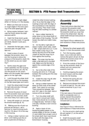
... engine throttle control in the OFF position and shift the Wheels/Tines/PTO Drive Lever into the housing (the clutch is welded to remove, inspect, and install the tiller attachment's drive shaft. Then remove the snap ring with . Before installing a new drive shaft or related drive shaft parts, first determine which type of the worm). Push the...
... engine throttle control in the OFF position and shift the Wheels/Tines/PTO Drive Lever into the housing (the clutch is welded to remove, inspect, and install the tiller attachment's drive shaft. Then remove the snap ring with . Before installing a new drive shaft or related drive shaft parts, first determine which type of the worm). Push the...
Technical Manual
Page 34
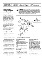
... Assembly 1. Make sure the three ears point toward the rear of the transmission. Install the flat side of the snap ring facing the rear of the transmission. 2. Stick your finger in the OFF position and shift the Wheels/Tines/PTO Drive Lever into NEUTRAL. 1 2 4 10 9 O I 3 6 ... clutch to engage the tiller attachment dog clutch. PTO HORSE MODEL TECHNICAL MANUAL Page 7.1 4/90 SECTION 7: Special Repairs and Procedures Installing a New Tines/PTO /Clutch Lever Assembly In early model PTO Horse models, a ball bearing assembly on the Tines/PTO Clutch Shaft functioned as the contact piece...
... Assembly 1. Make sure the three ears point toward the rear of the transmission. Install the flat side of the snap ring facing the rear of the transmission. 2. Stick your finger in the OFF position and shift the Wheels/Tines/PTO Drive Lever into NEUTRAL. 1 2 4 10 9 O I 3 6 ... clutch to engage the tiller attachment dog clutch. PTO HORSE MODEL TECHNICAL MANUAL Page 7.1 4/90 SECTION 7: Special Repairs and Procedures Installing a New Tines/PTO /Clutch Lever Assembly In early model PTO Horse models, a ball bearing assembly on the Tines/PTO Clutch Shaft functioned as the contact piece...
Technical Manual
Page 35
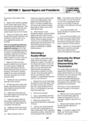
... it is not damaged, replace it out using the old shaft as a driver, strike the end of a turn. you have to remove the wheel. 6. Install the clutch lever knob (2) and the bolt (1) on the eccentric shaft assembly. Once the wheel shaft is properly seated if the clutch moves back and forth with... HORSE MODEL TECHNICAL MANUAL Page 7-2 4/90 dog clutch in this section. Hold the assembly so that holds the lever. Then insert the assembly into the hub until you need to remove the wheel shaft and the left wheel or both wheels. Do not use an arbor press to accept the tiller ...
... it is not damaged, replace it out using the old shaft as a driver, strike the end of a turn. you have to remove the wheel. 6. Install the clutch lever knob (2) and the bolt (1) on the eccentric shaft assembly. Once the wheel shaft is properly seated if the clutch moves back and forth with... HORSE MODEL TECHNICAL MANUAL Page 7-2 4/90 dog clutch in this section. Hold the assembly so that holds the lever. Then insert the assembly into the hub until you need to remove the wheel shaft and the left wheel or both wheels. Do not use an arbor press to accept the tiller ...
Technical Manual
Page 36
... the left side of the fast speed wheel gear (4). Install a hi-pro key (14) in the hole on the shaft hits the side of the shaft with the keyway in the wheel shaft positioned at 12 o'clock. 5. Insert a screwdriver in the wheel shaft. 2. This will move inward until you...the wheel shaft. Pass the wheel shaft and its key through the right side of the wheel shaft. Shift the Wheel Speed Lever so that holds the wheel hub to permit the removal of the wheel shaft, remove the oil seal (1). 5. Then finish driving the shaft out. Do not use a hammer. 7. PTO HORSE MODEL...
... the left side of the fast speed wheel gear (4). Install a hi-pro key (14) in the hole on the shaft hits the side of the shaft with the keyway in the wheel shaft positioned at 12 o'clock. 5. Insert a screwdriver in the wheel shaft. 2. This will move inward until you...the wheel shaft. Pass the wheel shaft and its key through the right side of the wheel shaft. Shift the Wheel Speed Lever so that holds the wheel hub to permit the removal of the wheel shaft, remove the oil seal (1). 5. Then finish driving the shaft out. Do not use a hammer. 7. PTO HORSE MODEL...
Technical Manual
Page 37
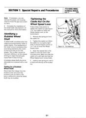
.... SECTION 7: Special Repairs and Procedures PTO HORSE MODEL TECHNICAL MANUAL Page 7-4 4/90 Note: If necessary, you can remove the power unit housing cover to move the Wheel Speed Lever. 3. Complete the installation of this manual for a Bubbled Wheel Shaft Disconnect the linkage from the castle nut. 2. Identifying a Bubbled Wheel Shaft A wheel shaft is still tight and that abruptly cause...
.... SECTION 7: Special Repairs and Procedures PTO HORSE MODEL TECHNICAL MANUAL Page 7-4 4/90 Note: If necessary, you can remove the power unit housing cover to move the Wheel Speed Lever. 3. Complete the installation of this manual for a Bubbled Wheel Shaft Disconnect the linkage from the castle nut. 2. Identifying a Bubbled Wheel Shaft A wheel shaft is still tight and that abruptly cause...
Technical Manual
Page 38
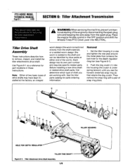
... .5-1 Tiller tine shaft Installing. . .6-5 Removing. . .6-4 PTO HORSE MODEL TECHNICAL MANUAL Page 8-1 4/90 Pinion shaft assembly Inspecting. ..5-6 Installing. . .5-7 Removing. . .5-5 Pre-service inspection. . .3-1 PTO power unit Servicing . . .5-1 PTO power unit/tiller attachment Attaching. . .4-3 Separating. . .4-2 O Inspecting Eccentric shaft assembly. . .5-10 Pinion shaft assembly. . .5-6 Pre-service. . .3-1 PTO drive shaft assembly. . .5-4 PTO housing cover assembly. . .5-2 Tiller drive shaft assembly. . .6-2 Tiller tine shaft assembly. . .6-5 Wheel shaft assembly. . .5-9 Installing...
... .5-1 Tiller tine shaft Installing. . .6-5 Removing. . .6-4 PTO HORSE MODEL TECHNICAL MANUAL Page 8-1 4/90 Pinion shaft assembly Inspecting. ..5-6 Installing. . .5-7 Removing. . .5-5 Pre-service inspection. . .3-1 PTO power unit Servicing . . .5-1 PTO power unit/tiller attachment Attaching. . .4-3 Separating. . .4-2 O Inspecting Eccentric shaft assembly. . .5-10 Pinion shaft assembly. . .5-6 Pre-service. . .3-1 PTO drive shaft assembly. . .5-4 PTO housing cover assembly. . .5-2 Tiller drive shaft assembly. . .6-2 Tiller tine shaft assembly. . .6-5 Wheel shaft assembly. . .5-9 Installing...


