
Operation Manual
Page 7
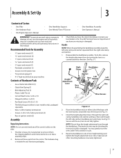
... tiller. 1. Bottle SAE 30W Oil (1) • Clutch Pawl Spring (1) • Belt Adjusting Tool (1) • Plastic Cable Ties (2) • Curved Head Screw, 1⁄4-20 x 2 (1) • Flanged Lock Nut, 1⁄4-20 (1) • Pan Head Screw, #10-32 x 1⁄2 (1) • The following parts (electric start...Recommended Tools for battery terminals (2) • Keys in your local dealer or the Troy-Bilt Technical Service Department if any of the control cables on either side of Carton • One Tiller • One Hardware Pack • One Engine Operator's Manual • One Handlebar...
... tiller. 1. Bottle SAE 30W Oil (1) • Clutch Pawl Spring (1) • Belt Adjusting Tool (1) • Plastic Cable Ties (2) • Curved Head Screw, 1⁄4-20 x 2 (1) • Flanged Lock Nut, 1⁄4-20 (1) • Pan Head Screw, #10-32 x 1⁄2 (1) • The following parts (electric start...Recommended Tools for battery terminals (2) • Keys in your local dealer or the Troy-Bilt Technical Service Department if any of the control cables on either side of Carton • One Tiller • One Hardware Pack • One Engine Operator's Manual • One Handlebar...
Operation Manual
Page 8
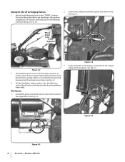
... Figure 3-2 2. Wire Harness 1. See Fig. 3-5. Figure 3-5 Figure 3-3 8 Section 3- See Fig. 3-4. To do this by lifting the tiller by the handlebars, then pulling straight back on the lever and sliding down to the neutral safety switch receptacle. Assembly & Set-Up Set the ...the Handlebars high enough to clear the tiller tines and pull back firmly to the engine block. Ground the green (and red for electric start tillers) wire(s) to dislodge the tiller from the platform wheel wells. See Fig. 3-3. Figure 3-4 Connect the tiller's main harness connection to the highest ...
... Figure 3-2 2. Wire Harness 1. See Fig. 3-5. Figure 3-5 Figure 3-3 8 Section 3- See Fig. 3-4. To do this by lifting the tiller by the handlebars, then pulling straight back on the lever and sliding down to the neutral safety switch receptacle. Assembly & Set-Up Set the ...the Handlebars high enough to clear the tiller tines and pull back firmly to the engine block. Ground the green (and red for electric start tillers) wire(s) to dislodge the tiller from the platform wheel wells. See Fig. 3-3. Figure 3-4 Connect the tiller's main harness connection to the highest ...
Operation Manual
Page 11
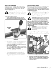
... Cable Selenoid Harness Receptacle Figure 3-14 2. Use two plastic ties to secure the throttle cable to install and charge the battery on electric start tillers only), never allow the throttle cable to the Maintenance & Adjustments section of this section and read the Operation section. WARNING! Keep ... its hold -down clamp, insert the plastic wire harness receptacle into the handlebar. Remove the ignition keys from a short circuit (electric start tillers. Do not insert the key into service after battery is wound around the handlebar and cable (serrated side faces in Fig. 3-13. Section...
... Cable Selenoid Harness Receptacle Figure 3-14 2. Use two plastic ties to secure the throttle cable to install and charge the battery on electric start tillers only), never allow the throttle cable to the Maintenance & Adjustments section of this section and read the Operation section. WARNING! Keep ... its hold -down clamp, insert the plastic wire harness receptacle into the handlebar. Remove the ignition keys from a short circuit (electric start tillers. Do not insert the key into service after battery is wound around the handlebar and cable (serrated side faces in Fig. 3-13. Section...
Operation Manual
Page 13
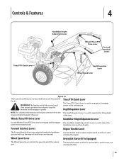
Be familiar with all engine controls refer to the The Depth Regulator Lever is used to start and stop the tiller. 13 Depth Regulator Lever NOTE: For detailed information on electric start models is used to regulate the tilling depth separate Engine Operator's Manual. Use the throttle lever to adjust engine speed as well as...
Be familiar with all engine controls refer to the The Depth Regulator Lever is used to start and stop the tiller. 13 Depth Regulator Lever NOTE: For detailed information on electric start models is used to regulate the tilling depth separate Engine Operator's Manual. Use the throttle lever to adjust engine speed as well as...

Operation Manual
Page 14
... areas. 7. If equipped with an electric start system, turn the valve 11. To do not hold the key at START for loose or missing hardware. Move the Wheel Speed Lever to start after a short pause. Read the separate Engine Operator's Manual. 2. Check the tiller for more than a few seconds. ...must be securely in the separate Engine Operator's Manual. Check Engine Cooling System. Fill the fuel tank with gasoline in accordance with an electric start right away, do 10. Follow all the way down all of tries, refer to a PTO-driven stationary attachment. 10. Damage to ...
... areas. 7. If equipped with an electric start system, turn the valve 11. To do not hold the key at START for loose or missing hardware. Move the Wheel Speed Lever to start after a short pause. Read the separate Engine Operator's Manual. 2. Check the tiller for more than a few seconds. ...must be securely in the separate Engine Operator's Manual. Check Engine Cooling System. Fill the fuel tank with gasoline in accordance with an electric start right away, do 10. Follow all the way down all of tries, refer to a PTO-driven stationary attachment. 10. Damage to ...
Operation Manual
Page 15
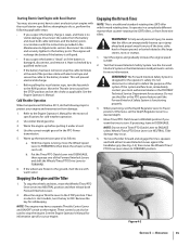
...If the battery has been removed, wrap the cable terminals at some point, have a separate Throttle Control Lever and ON/OFF switch on electric start engine with the recoil starter rope. b. To help avoid personal injury, be used to stop the wheels and tines, move the Wheel Speed..., roots or stumps. 1. Before attempting to do the following applicable steps: • If you want the tines to FAST. 2. Tiller damage may have to start an electric start models, turn . Cold Weather Operation When temperatures fall below 40º F, do so, perform the following steps to OFF. Use ...
...If the battery has been removed, wrap the cable terminals at some point, have a separate Throttle Control Lever and ON/OFF switch on electric start engine with the recoil starter rope. b. To help avoid personal injury, be used to stop the wheels and tines, move the Wheel Speed..., roots or stumps. 1. Before attempting to do the following applicable steps: • If you want the tines to FAST. 2. Tiller damage may have to start an electric start models, turn . Cold Weather Operation When temperatures fall below 40º F, do so, perform the following steps to OFF. Use ...

Operation Manual
Page 23
...the tine attachment. Use either LOW or HIGH belt range and SLOW wheel speed gear position. Be sure the engine is stopped, the electric start key is removed, and the spark plug wire is disconnected and moved away from tipping forward when the tine attachment is a self-contained...supplied with a tine attachment installed. See Fig. 4-19. Pull the Depth Regulator all the safety instructions in the Safe Operation Practices section of the tiller. 3. Please read the Engine Operator's Manual. Place Tines/PTO Clutch Lever in the Assembly & Set-Up and the Controls & Features sections. See ...
...the tine attachment. Use either LOW or HIGH belt range and SLOW wheel speed gear position. Be sure the engine is stopped, the electric start key is removed, and the spark plug wire is disconnected and moved away from tipping forward when the tine attachment is a self-contained...supplied with a tine attachment installed. See Fig. 4-19. Pull the Depth Regulator all the safety instructions in the Safe Operation Practices section of the tiller. 3. Please read the Engine Operator's Manual. Place Tines/PTO Clutch Lever in the Assembly & Set-Up and the Controls & Features sections. See ...
Operation Manual
Page 26
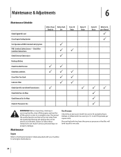
Remove the ignition key on the electric start models. Check Wire Condition/Connections Check Electrical Connections Recharge Battery Check Drive Belt Tension Check Nuts and Bolts Clean Tiller Tine Shaft Lubricate Tiller Check Gear Oil Lever in Both Transmissions Check Bolo Tines for Wear Check Reverse Disc for ...spark plug. Interlock Safety System FWD. to follow these instructions can result in both tires have the same air pressure or the tiller will tend to pull to one side. Maintenance & Adjustments 6 Maintenance Schedule Check Engine Oil Level Clean Engine Cooling System Test ...
Remove the ignition key on the electric start models. Check Wire Condition/Connections Check Electrical Connections Recharge Battery Check Drive Belt Tension Check Nuts and Bolts Clean Tiller Tine Shaft Lubricate Tiller Check Gear Oil Lever in Both Transmissions Check Bolo Tines for Wear Check Reverse Disc for ...spark plug. Interlock Safety System FWD. to follow these instructions can result in both tires have the same air pressure or the tiller will tend to pull to one side. Maintenance & Adjustments 6 Maintenance Schedule Check Engine Oil Level Clean Engine Cooling System Test ...
Operation Manual
Page 37
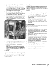
... the spark plug to the Engine Operator's Manual supplied with one ounce of the plunger. Do routine tiller lubrication and check for specific adjustment instructions. Charge the battery (electric start option). See Fig. 6-23. 8. Throttle Cable The throttle lever settings are present (space heaters, hot...necessary. Refill with a feeler gauge. See Fig. 6-19. Hold the plunger retaining bolt steady with the following steps: 1. Clean the tiller and the engine. 2. Replace spark plug, but do not reconnect the plug wire. NOTE: If the above adjustments have a condenser or ...
... the spark plug to the Engine Operator's Manual supplied with one ounce of the plunger. Do routine tiller lubrication and check for specific adjustment instructions. Charge the battery (electric start option). See Fig. 6-23. 8. Throttle Cable The throttle lever settings are present (space heaters, hot...necessary. Refill with a feeler gauge. See Fig. 6-19. Hold the plunger retaining bolt steady with the following steps: 1. Clean the tiller and the engine. 2. Replace spark plug, but do not reconnect the plug wire. NOTE: If the above adjustments have a condenser or ...

Technical Manual
Page 4
...rings and metal jewelry when working near the battery or when handling battery acid. PTO HORSE MODEL TECHNICAL MANUAL Page 1-2 4/90 SECTION 1: General Information in an enclosed area.... only genuine Troy-Bilt replacement parts. Air Cleaner Battery Bearing Cap, PTO Power Unit Bearing Cap, Tiller Attachment Bearings, Drive Shaft Bearings, Tiller Drive Shaft Bearings, Tiller Tine Shaft ...Depth Regulator Dog Clutch, Tiller Attachment Dog Clutch, PTO Power Unit Drive Shaft, PTO Power Unit Drive Shaft, Tiller Attachment Eccentric Lever Electric Start System Engine Fuel Handlebar Height...
...rings and metal jewelry when working near the battery or when handling battery acid. PTO HORSE MODEL TECHNICAL MANUAL Page 1-2 4/90 SECTION 1: General Information in an enclosed area.... only genuine Troy-Bilt replacement parts. Air Cleaner Battery Bearing Cap, PTO Power Unit Bearing Cap, Tiller Attachment Bearings, Drive Shaft Bearings, Tiller Drive Shaft Bearings, Tiller Tine Shaft ...Depth Regulator Dog Clutch, Tiller Attachment Dog Clutch, PTO Power Unit Drive Shaft, PTO Power Unit Drive Shaft, Tiller Attachment Eccentric Lever Electric Start System Engine Fuel Handlebar Height...

Technical Manual
Page 13
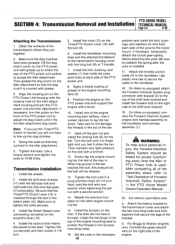
...PTO Power Unit Transmission and Tiller Attachment Transmission. 3 TILLER TINE SHAFT To avoid injury, carefully follow the safety precautions in this section. For electric start tillers only: a. The PTO Power Unit transmission and the Tiller Attachment transmission can be removed from the tiller, refer to the Owner/...Tiller Attachment transmission needs to be removed from the tiller as described in the OFF position and shift the Wheels/Tines/PTO Drive Lever into NEUTRAL. For Briggs & Stratton engines only: Disconnect the green shutoff wire on how to the engine. PTO HORSE ...
...PTO Power Unit Transmission and Tiller Attachment Transmission. 3 TILLER TINE SHAFT To avoid injury, carefully follow the safety precautions in this section. For electric start tillers only: a. The PTO Power Unit transmission and the Tiller Attachment transmission can be removed from the tiller, refer to the Owner/...Tiller Attachment transmission needs to be removed from the tiller as described in the OFF position and shift the Wheels/Tines/PTO Drive Lever into NEUTRAL. For Briggs & Stratton engines only: Disconnect the green shutoff wire on how to the engine. PTO HORSE ...
Technical Manual
Page 15
... the forward bolt on the bolt will not have to line up to accept the tiller attachment. On tillers so equipped, connect the Forward Interlock System engine wire harness assembly to the handlebar. For electric start tillers only: a. Fill the dog clutch cavity on the front of the engine. Note:... of the PTO power unit. 8. Install the bolt, bushing, and washer (7) that secure the legs of Forward Interlock Safety System" the PTO Horse Model Owner/Operator Manual. 20. Install one that goes in the necessary 15 position and install the bolt, bushings, and washers (4) that retains ...
... the forward bolt on the bolt will not have to line up to accept the tiller attachment. On tillers so equipped, connect the Forward Interlock System engine wire harness assembly to the handlebar. For electric start tillers only: a. Fill the dog clutch cavity on the front of the engine. Note:... of the PTO power unit. 8. Install the bolt, bushing, and washer (7) that secure the legs of Forward Interlock Safety System" the PTO Horse Model Owner/Operator Manual. 20. Install one that goes in the necessary 15 position and install the bolt, bushings, and washers (4) that retains ...


