
Operation Manual
Page 7
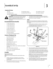
... severely bend any items are complete and you have read and understand the safety and operating instructions in your local dealer or the Troy-Bilt Technical Service Department if any of the control cables on either side of the base, with the nut, but do so in these... Wire Harness Figure 3-1 2. Place the handlebar ends on the tiller. 1. Secure with the wire harness toward the rear of Carton • One Tiller • One Hardware Pack • One Engine Operator's Manual • One Handlebar Support • One Wheels/Tines PTO Lever • One Handlebar Assembly • One ...
... severely bend any items are complete and you have read and understand the safety and operating instructions in your local dealer or the Troy-Bilt Technical Service Department if any of the control cables on either side of the base, with the nut, but do so in these... Wire Harness Figure 3-1 2. Place the handlebar ends on the tiller. 1. Secure with the wire harness toward the rear of Carton • One Tiller • One Hardware Pack • One Engine Operator's Manual • One Handlebar Support • One Wheels/Tines PTO Lever • One Handlebar Assembly • One ...
Operation Manual
Page 8
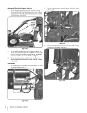
...Fast and Slow settings while you rock the tiller forward and backward until the wheels move freely. Assembly & Set-Up Set the Depth Regulator Lever to dislodge the tiller from the platform wheel wells. Ground the green (and red for electric start tillers) wire(s) to the Freewheel position. See Fig.... 3-5. To do this by lifting the tiller by the handlebars, then pulling straight back on the ...
...Fast and Slow settings while you rock the tiller forward and backward until the wheels move freely. Assembly & Set-Up Set the Depth Regulator Lever to dislodge the tiller from the platform wheel wells. Ground the green (and red for electric start tillers) wire(s) to the Freewheel position. See Fig.... 3-5. To do this by lifting the tiller by the handlebars, then pulling straight back on the ...
Operation Manual
Page 9
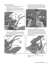
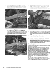
... Long Link Short Link Figure 3-6 3. Install the wider hook end of the clutch pawl spring down into the small hole at the end of the Wheels/Tines/PTO Lever over stretch the spring while installing. Install the star washer 2. Clutch Pawl Spring Long Link Bar Figure 3-7 Figure 3-9 NOTE: Do not ...the screw through the lever and yoke plates. To aid in the next step, insert a screw temporarily into the hole in Step 3 and move the Wheels/Tines/PTO Lever fully forward. Remove the temporary screw from the forward holes inserted in the long link bar. Assembly & Set-Up 9 Loosen the bolt...
... Long Link Short Link Figure 3-6 3. Install the wider hook end of the clutch pawl spring down into the small hole at the end of the Wheels/Tines/PTO Lever over stretch the spring while installing. Install the star washer 2. Clutch Pawl Spring Long Link Bar Figure 3-7 Figure 3-9 NOTE: Do not ...the screw through the lever and yoke plates. To aid in the next step, insert a screw temporarily into the hole in Step 3 and move the Wheels/Tines/PTO Lever fully forward. Remove the temporary screw from the forward holes inserted in the long link bar. Assembly & Set-Up 9 Loosen the bolt...
Operation Manual
Page 10
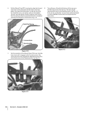
To test Reverse, lift and hold the lever all other hardware. Completed instructions. Test the operation of the Wheels/Tines/PTO Lever. See Fig. 3-11. Pull the Wheels/Tines/PTO Lever back to the Neutral position. See Fig. 3-12. bar. Push the lever down until it engages in the lever...Department for that is properly seated at both ends. Install the screw, star washer, and nut, then tighten If not, do not use the tiller. assembly should plates. Clutch Pawl Spring Forward Hole Short Link Bar Figure 3-10 7. Next, move the lever up in most holes in the yoke...
To test Reverse, lift and hold the lever all other hardware. Completed instructions. Test the operation of the Wheels/Tines/PTO Lever. See Fig. 3-11. Pull the Wheels/Tines/PTO Lever back to the Neutral position. See Fig. 3-12. bar. Push the lever down until it engages in the lever...Department for that is properly seated at both ends. Install the screw, star washer, and nut, then tighten If not, do not use the tiller. assembly should plates. Clutch Pawl Spring Forward Hole Short Link Bar Figure 3-10 7. Next, move the lever up in most holes in the yoke...
Operation Manual
Page 13
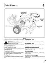
Controls & Features 4 Tines/PTO Clutch Lever Handlebar Height Adjustment Lever Wheels/Tines/PTO Drive Lever Forward Interlock Levers Depth Regulator Lever Wheel Speed Lever Figure 4-1 Tiller controls and features are released. Use the throttle lever to adjust engine speed as well as to ... two heights. handlebars to regulate the tilling depth separate Engine Operator's Manual. Wheel Speed Lever Keyswitch Starter (If So Equipped) The Wheel Speed Lever controls the speed at which the wheels spin. The keyswitch starter on all the controls and power to start and stop...
Controls & Features 4 Tines/PTO Clutch Lever Handlebar Height Adjustment Lever Wheels/Tines/PTO Drive Lever Forward Interlock Levers Depth Regulator Lever Wheel Speed Lever Figure 4-1 Tiller controls and features are released. Use the throttle lever to adjust engine speed as well as to ... two heights. handlebars to regulate the tilling depth separate Engine Operator's Manual. Wheel Speed Lever Keyswitch Starter (If So Equipped) The Wheel Speed Lever controls the speed at which the wheels spin. The keyswitch starter on all the controls and power to start and stop...

Operation Manual
Page 14
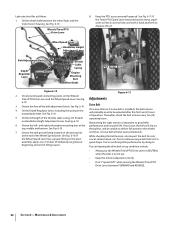
... areas may exceed 150° F. Move the Wheel Speed Lever to FAST setting when tilling. 14 Pre-Start Checklist Make the following checks and perform the following steps describe how to Lever in place. 6. Check the tiller for more information on the fuel tank to prevent...valve 11. Read the separate Engine Operator's Manual. 2. Blocks Blocks 5. Move the Tines/PTO Clutch Lever into FREEWHEEL and block the wheels to stabilize the tiller when you have read all instructions and safety rules carefully. 6. to ON. Never run the engine indoors or in the separate Engine ...
... areas may exceed 150° F. Move the Wheel Speed Lever to FAST setting when tilling. 14 Pre-Start Checklist Make the following checks and perform the following steps describe how to Lever in place. 6. Check the tiller for more information on the fuel tank to prevent...valve 11. Read the separate Engine Operator's Manual. 2. Blocks Blocks 5. Move the Tines/PTO Clutch Lever into FREEWHEEL and block the wheels to stabilize the tiller when you have read all instructions and safety rules carefully. 6. to ON. Never run the engine indoors or in the separate Engine ...
Operation Manual
Page 15
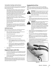
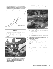
...40º F, do so, perform the following steps to FREEWHEEL (then block the wheels so they can also be aware that the tiller can unexpectedly bounce up the transmission gear oil as applicable. b. If the wheels are frozen to the ground, melt the ice with electrical tape and secure the .../PTO Drive Lever into DISENGAGE, then squeeze one of the Forward Interlock Levers and shift the Wheels/Tines/PTO Drive Lever to the STOP position. To move the tiller forward and engage the tines, squeeze and hold either Forward Interlock Lever against the handlebar grip (See Fig. 4-2), then move...
...40º F, do so, perform the following steps to FREEWHEEL (then block the wheels so they can also be aware that the tiller can unexpectedly bounce up the transmission gear oil as applicable. b. If the wheels are frozen to the ground, melt the ice with electrical tape and secure the .../PTO Drive Lever into DISENGAGE, then squeeze one of the Forward Interlock Levers and shift the Wheels/Tines/PTO Drive Lever to the STOP position. To move the tiller forward and engage the tines, squeeze and hold either Forward Interlock Lever against the handlebar grip (See Fig. 4-2), then move...
Operation Manual
Page 16
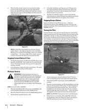
...emergency, release all the way and to propel the tiller. Disengage the tines, reduce engine speed, and move the Wheel Speed Lever to ENGAGE position and resume forward operation. 16 Section 5- When the tiller moves forward, relax and let the wheels 4. Walk on the side that the area behind.../PTO Drive Lever all of the turn is not yet up the handlebars. Avoid using FAST wheel speed until the tines are familiar with backing the tiller. 3. Move the Tines/PTO Clutch Lever into the DISENGAGE position. Move the Tines/PTO Clutch Lever into DISENGAGE position. 3. ...
...emergency, release all the way and to propel the tiller. Disengage the tines, reduce engine speed, and move the Wheel Speed Lever to ENGAGE position and resume forward operation. 16 Section 5- When the tiller moves forward, relax and let the wheels 4. Walk on the side that the area behind.../PTO Drive Lever all of the turn is not yet up the handlebars. Avoid using FAST wheel speed until the tines are familiar with backing the tiller. 3. Move the Tines/PTO Clutch Lever into the DISENGAGE position. Move the Tines/PTO Clutch Lever into DISENGAGE position. 3. ...
Operation Manual
Page 17
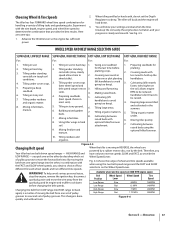
... handlebars to avoid handlebars don't have only two reverse speeds SLOW and FAST, as set of wheel and tine speeds available when using the 9. Tilling organic matter 8. Using tiller wings in hard clay. 2. Belt Position Wheel Speed Lever Wheel Speed Tine Speed Low Range Slow .5 MPH 146RPM before planting. 3. Figure 4-6 Section 5 - See Fig. 4-5. Tilling...
... handlebars to avoid handlebars don't have only two reverse speeds SLOW and FAST, as set of wheel and tine speeds available when using the 9. Tilling organic matter 8. Using tiller wings in hard clay. 2. Belt Position Wheel Speed Lever Wheel Speed Tine Speed Low Range Slow .5 MPH 146RPM before planting. 3. Figure 4-6 Section 5 - See Fig. 4-5. Tilling...

Operation Manual
Page 18
... Range 5. Check both sides of the tiller. Operation To create belt slack, reach over to the right side of the pulleys and push in at the fastest pace. NOTE: If extra belt slack is properly seated. Let engine and muffler cool. 2. Move the Wheels/Tines/PTO Drive Lever into NEUTRAL. See... injury, shut off the engine, let all moving parts come to the other side of the belt with a FAST wheel speed setting propels the tiller at the center of the tiller to finish seating the belt onto the pulley groove. Changing Belt From Low Range to work the belt as possible onto...
... Range 5. Check both sides of the tiller. Operation To create belt slack, reach over to the right side of the pulleys and push in at the fastest pace. NOTE: If extra belt slack is properly seated. Let engine and muffler cool. 2. Move the Wheels/Tines/PTO Drive Lever into NEUTRAL. See... injury, shut off the engine, let all moving parts come to the other side of the belt with a FAST wheel speed setting propels the tiller at the center of the tiller to finish seating the belt onto the pulley groove. Changing Belt From Low Range to work the belt as possible onto...

Operation Manual
Page 19
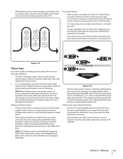
...roots often grow close to dig deeper. 3. Top-Rear Gear Tilling Tips & Techniques Figure 4-9 Let the Tiller Do the Work • While tilling, relax and let the wheels pull the tiller along 4. Refer to skip rapidly across the ground. Check that the belt is not 5. See Fig. ...reduce tangling, set for the first passes through a particularly tough section of the tiller, move the belt off the powered wheels, causing them to help get maximum "chopping" action as will help destroy weeds - Wheels/Tines/PTO Drive Lever Top-Front Gear Clearing the Tines The tines have a...
...roots often grow close to dig deeper. 3. Top-Rear Gear Tilling Tips & Techniques Figure 4-9 Let the Tiller Do the Work • While tilling, relax and let the wheels pull the tiller along 4. Refer to skip rapidly across the ground. Check that the belt is not 5. See Fig. ...reduce tangling, set for the first passes through a particularly tough section of the tiller, move the belt off the powered wheels, causing them to help get maximum "chopping" action as will help destroy weeds - Wheels/Tines/PTO Drive Lever Top-Front Gear Clearing the Tines The tines have a...
Operation Manual
Page 21
...'t practical for more information on which to -3 feet wide. See Fig. 4-14. • When a slope is started by about 1⁄2 the width of the tiller. Tilling vertically on Slopes If you can starve engine parts of the slope and work down slopes rather than it does downhill. This untilled strip... leaves room for plants. • To create a terrace, start at all times. NOTE: For the best results, use the HIGH belt range and SLOW wheel speed lever position. The incline of the slope will expose poor subsoil that are rows that is not too Steep for future plant growth. See...
...'t practical for more information on which to -3 feet wide. See Fig. 4-14. • When a slope is started by about 1⁄2 the width of the tiller. Tilling vertically on Slopes If you can starve engine parts of the slope and work down slopes rather than it does downhill. This untilled strip... leaves room for plants. • To create a terrace, start at all times. NOTE: For the best results, use the HIGH belt range and SLOW wheel speed lever position. The incline of the slope will expose poor subsoil that are rows that is not too Steep for future plant growth. See...
Operation Manual
Page 22
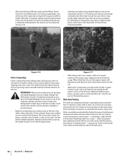
... leftover vines, stalks, stems and roots. Preparing wide rows is spreading seeds anywhere from 3 to 4 times (or more) produce in loss of tiller control, property damage or personal injury. • Begin by "fishtailing" or frequently using reverse. Cover with soil and tamp the area firmly with ...the soft, newly tilled soil. And of excessive tangling in terrace gardening, start composted. • Move the belt into LOW belt range and the Wheel Speed • Standing cornstalks of reasonable height can grow anywhere from 10 inches to 2 feet wide or more. Grow a crop of clover, ...
... leftover vines, stalks, stems and roots. Preparing wide rows is spreading seeds anywhere from 3 to 4 times (or more) produce in loss of tiller control, property damage or personal injury. • Begin by "fishtailing" or frequently using reverse. Cover with soil and tamp the area firmly with ...the soft, newly tilled soil. And of excessive tangling in terrace gardening, start composted. • Move the belt into LOW belt range and the Wheel Speed • Standing cornstalks of reasonable height can grow anywhere from 10 inches to 2 feet wide or more. Grow a crop of clover, ...

Operation Manual
Page 23
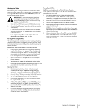
... to level ground. 2. Use either LOW or HIGH belt range and SLOW wheel speed gear position. Figure 4-12 NOTE: Before operating your PTO Power machine. Each new pass should be tilled into a row of the tiller. 3. Dry plants are much easier for the first time, make sure that... the stalks go between the left wheel and the transmission case. See Fig. 4-18. Place Wheel Speed Lever into NEUTRAL. See Fig. 4-20. The following instructions...
... to level ground. 2. Use either LOW or HIGH belt range and SLOW wheel speed gear position. Figure 4-12 NOTE: Before operating your PTO Power machine. Each new pass should be tilled into a row of the tiller. 3. Dry plants are much easier for the first time, make sure that... the stalks go between the left wheel and the transmission case. See Fig. 4-18. Place Wheel Speed Lever into NEUTRAL. See Fig. 4-20. The following instructions...
Operation Manual
Page 25
... vehicle. • Operators should be strong enough to support the combined weight of the tiller and the operator. Leave Wheel Speed Lever in FAST or SLOW position, chock the wheels with blocks and tie down the ramp to ensure that they should provide good traction to...5. Follow these steps before loading and unloading the tiller. and they move the tiller backward. your tiller. Move Wheel Speed Lever into DISENGAGE position. 3. The tiller could tip forward and expose you move Wheel Speed Lever to FREEWHEEL, and manually push the tiller. Move the Tines/PTO Clutch Lever to SLOW ...
... vehicle. • Operators should be strong enough to support the combined weight of the tiller and the operator. Leave Wheel Speed Lever in FAST or SLOW position, chock the wheels with blocks and tie down the ramp to ensure that they should provide good traction to...5. Follow these steps before loading and unloading the tiller. and they move the tiller backward. your tiller. Move Wheel Speed Lever into DISENGAGE position. 3. The tiller could tip forward and expose you move Wheel Speed Lever to FREEWHEEL, and manually push the tiller. Move the Tines/PTO Clutch Lever to SLOW ...
Operation Manual
Page 27
... Tine holders and clear away dirt and debris that has accumulated on your tiller is located on the tine shaft or inside the tine holders. Wheel Shaft Maintenance After every 10 operating hours, remove the wheels and clear away dirt and debris that have accumulated on the left -...grease to the tine shaft. After cleaning away any debris and removing old grease from the tine shaft, apply fresh grease to the wheel shaft before re-installing the wheels. Maintenance & Adjustments 27 Hardware Check for loose or missing hardware every ten (10) operating hours. See Fig. 6-2. Jam Nut Figure...
... Tine holders and clear away dirt and debris that has accumulated on your tiller is located on the tine shaft or inside the tine holders. Wheel Shaft Maintenance After every 10 operating hours, remove the wheels and clear away dirt and debris that have accumulated on the left -...grease to the tine shaft. After cleaning away any debris and removing old grease from the tine shaft, apply fresh grease to the wheel shaft before re-installing the wheels. Maintenance & Adjustments 27 Hardware Check for loose or missing hardware every ten (10) operating hours. See Fig. 6-2. Jam Nut Figure...

Operation Manual
Page 31
...Lever setting: a. Add 1⁄2-ounce at the rear of the lower screws from running. It takes about two quarts have drained, tilt the tiller forward so any oil at a time to avoid overfilling. The tine attachment transmission is not equipped with a metal lubricant where grease is recommended... Interlock System The wiring circuit for the Forward Interlock Safety System is a fourth switch located in the circuit which, when open whenever the Wheels/ Tines/PTO Drive Lever is acceptable). There are on the pulleys. One switch is specified. This switch is in the dipstick hole. ...
...Lever setting: a. Add 1⁄2-ounce at the rear of the lower screws from running. It takes about two quarts have drained, tilt the tiller forward so any oil at a time to avoid overfilling. The tine attachment transmission is not equipped with a metal lubricant where grease is recommended... Interlock System The wiring circuit for the Forward Interlock Safety System is a fourth switch located in the circuit which, when open whenever the Wheels/ Tines/PTO Drive Lever is acceptable). There are on the pulleys. One switch is specified. This switch is in the dipstick hole. ...
Operation Manual
Page 32
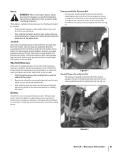
... oil into its access hole, and work it back and forth to be unable to deliver full power to good tiller 6. Wheel Speed Lever Handlebar Height Adjustment Lever Belt Adjustment Block Depth Regulator Lever Grease Fitting Throttle Cable Casing Engine Mounting Bars... fitting on keeping the drive belt in top condition include: • Always put the Wheels/Tines/PTO Drive Lever in NEUTRAL when the tiller is important to the wheels 7. See Fig. 6-10. Lubricate the tiller as follows: 1. Oil the wheel shaft between FORWARD and REVERSE. 32 Section 6- See Fig. 6-10. See Fig....
... oil into its access hole, and work it back and forth to be unable to deliver full power to good tiller 6. Wheel Speed Lever Handlebar Height Adjustment Lever Belt Adjustment Block Depth Regulator Lever Grease Fitting Throttle Cable Casing Engine Mounting Bars... fitting on keeping the drive belt in top condition include: • Always put the Wheels/Tines/PTO Drive Lever in NEUTRAL when the tiller is important to the wheels 7. See Fig. 6-10. Lubricate the tiller as follows: 1. Oil the wheel shaft between FORWARD and REVERSE. 32 Section 6- See Fig. 6-10. See Fig....
Operation Manual
Page 33
... bracket. If only the slotted portion of the tool will only need the belt adjustment tool you won't get a false belt tension reading. 4. Move the Wheels/Tines/PTO Drive Lever fully down . d. Figure 6-13 3. See Fig. 6-13. Before taking a measurement, be positioned underneath the belt adjustment too loose....the slotted part of the tool will tighten the belt; Don't let the clutch roller move the Wheels/Tines/PTO Drive Lever back to the tension is any binding, you received with your new tiller. If the full thickness (5⁄16") of the c. As described in , the belt is...
... bracket. If only the slotted portion of the tool will only need the belt adjustment tool you won't get a false belt tension reading. 4. Move the Wheels/Tines/PTO Drive Lever fully down . d. Figure 6-13 3. See Fig. 6-13. Before taking a measurement, be positioned underneath the belt adjustment too loose....the slotted part of the tool will tighten the belt; Don't let the clutch roller move the Wheels/Tines/PTO Drive Lever back to the tension is any binding, you received with your new tiller. If the full thickness (5⁄16") of the c. As described in , the belt is...
Operation Manual
Page 34
... through the hole in FORWARD position. the bolt at the back of steel with a special, long-lasting rubber compound bonded to be loosened. Place the Wheels/Tines/PTO Drive Lever in the side of the adjustment block, spacing the ends of the drive lever and remove the belt adjustment tool from... in REVERSE position, this rotating disc contacts the transmission drive pulley. NOTE: If the adjustment block is all the way down . When you raise the Wheels/Tines/PTO Drive Lever up if the belt needs to loosen - The drive shaft then turns the...
... through the hole in FORWARD position. the bolt at the back of steel with a special, long-lasting rubber compound bonded to be loosened. Place the Wheels/Tines/PTO Drive Lever in the side of the adjustment block, spacing the ends of the drive lever and remove the belt adjustment tool from... in REVERSE position, this rotating disc contacts the transmission drive pulley. NOTE: If the adjustment block is all the way down . When you raise the Wheels/Tines/PTO Drive Lever up if the belt needs to loosen - The drive shaft then turns the...


