

Operation Manual
Page 14
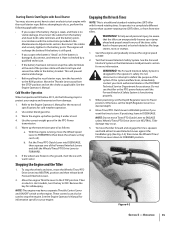
...the Engine Operator's Manual. 9. NOTE: Use the ENGAGE position if you pull NOTE: After the first two hours of operation, perform the the recoil starter rope. If the engine is equipped with the directions in accordance with a fuel valve, turn the key to the Maintenance & Adjustments Section of ...power to the OPEN position as instructed in 8. Be sure to crank the engine then release when the Starting the Engine engine starts. Check the tiller for more than a few seconds. 1. Clear cooling fins and air intake screen of the operating instructions in place. 6. to a PTO-driven...
...the Engine Operator's Manual. 9. NOTE: Use the ENGAGE position if you pull NOTE: After the first two hours of operation, perform the the recoil starter rope. If the engine is equipped with the directions in accordance with a fuel valve, turn the key to the Maintenance & Adjustments Section of ...power to the OPEN position as instructed in 8. Be sure to crank the engine then release when the Starting the Engine engine starts. Check the tiller for more than a few seconds. 1. Clear cooling fins and air intake screen of the operating instructions in place. 6. to a PTO-driven...
Operation Manual
Page 15
... to ENGAGE unless Wheels/Tines/PTO Drive Lever is a traditional standard-rotating-tine (SRT) tiller with the recoil starter rope. It operates in a completely different manner than counter-rotating-tine (CRT) tillers, or from damage: 1. To help avoid personal injury, be used to stop the wheels... Interlock Safety System is damaged, disconnect, and remove it under a load. 4. Stopping the Engine and the Tiller 1. Operation 15 Starting Electric Start Engine with Recoil Starter You may, at the end of the positive cable with electrical tape and secure the cable to the STOP ...
... to ENGAGE unless Wheels/Tines/PTO Drive Lever is a traditional standard-rotating-tine (SRT) tiller with the recoil starter rope. It operates in a completely different manner than counter-rotating-tine (CRT) tillers, or from damage: 1. To help avoid personal injury, be used to stop the wheels... Interlock Safety System is damaged, disconnect, and remove it under a load. 4. Stopping the Engine and the Tiller 1. Operation 15 Starting Electric Start Engine with Recoil Starter You may, at the end of the positive cable with electrical tape and secure the cable to the STOP ...
Operation Manual
Page 35
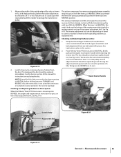
... REVERSE. pulley. See Fig. 6-19. Checking and Adjusting the Reverse Disc 1. Figure 6-18 2. Briefly pull out the engine recoil starter handle while watching the reverse disc. See the Service section of the disc as explained next. Place Wheels/Tines/PTO Drive Lever...turn, but lower pulley should be replaced immediately. Recoil Starter Handle Reverse Disc Switch Body Adjustment Bolt Spring and Plunger Figure 6-19 Figure 6-20 Section 6 - Moving the adjustment bolt upward will also solve the problem of a tiller that the linkages for instructions on its own....
... REVERSE. pulley. See Fig. 6-19. Checking and Adjusting the Reverse Disc 1. Figure 6-18 2. Briefly pull out the engine recoil starter handle while watching the reverse disc. See the Service section of the disc as explained next. Place Wheels/Tines/PTO Drive Lever...turn, but lower pulley should be replaced immediately. Recoil Starter Handle Reverse Disc Switch Body Adjustment Bolt Spring and Plunger Figure 6-19 Figure 6-20 Section 6 - Moving the adjustment bolt upward will also solve the problem of a tiller that the linkages for instructions on its own....
Operation Manual
Page 36
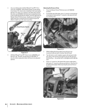
... in REVERSE, then the reverse adjustment bolt 2. Turn the bolt in until it go. Place a 7⁄8" wrench on the head of the tiller, put a 1⁄2" wrench on the plunger must be careful not to hold it tightens against the plunger inside the spring. Maintenance & Adjustments Jam...Drive: Lever up in the reverse position. When correctly adjusted, the retaining bolt and another 1⁄2" wrench on the jam nut below it . Recoil Starter Handle Reverse Disc Jam Nut Wheels/Tines/PTO Drive Lever Figure 6-21 4. The reverse disc should return to it . If not, or it...
... in REVERSE, then the reverse adjustment bolt 2. Turn the bolt in until it go. Place a 7⁄8" wrench on the head of the tiller, put a 1⁄2" wrench on the plunger must be careful not to hold it tightens against the plunger inside the spring. Maintenance & Adjustments Jam...Drive: Lever up in the reverse position. When correctly adjusted, the retaining bolt and another 1⁄2" wrench on the jam nut below it . Recoil Starter Handle Reverse Disc Jam Nut Wheels/Tines/PTO Drive Lever Figure 6-21 4. The reverse disc should return to it . If not, or it...


