
Operation Manual
Page 17
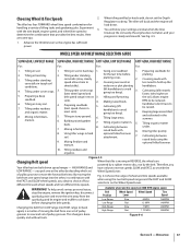
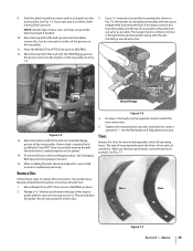
... and furrowing. RPM to 2. Tilling under standing cornstalks (slow, steady planting crops. 2. To help avoid serious personal injury, stop the engine, remove the ignition key, disconnect spark plug wire and move the forward belt into the other by the belt. Figure 4-6 Section 5 - Tilling in ... by deciding which set of moving in tough soil speed allows time to be raised). The tiller will buck and the engine will know your progress is a matter of pulley grooves. You will load down Available wheel and tine speeds at 3000 RPM engine speed. Tilling...
... and furrowing. RPM to 2. Tilling under standing cornstalks (slow, steady planting crops. 2. To help avoid serious personal injury, stop the engine, remove the ignition key, disconnect spark plug wire and move the forward belt into the other by the belt. Figure 4-6 Section 5 - Tilling in ... by deciding which set of moving in tough soil speed allows time to be raised). The tiller will buck and the engine will know your progress is a matter of pulley grooves. You will load down Available wheel and tine speeds at 3000 RPM engine speed. Tilling...

Operation Manual
Page 19
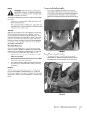
...handlebars slightly to prevent the tines from side to side (about 6" to dig another inch or two deeper. Check this won't be necessary to remove the debris by hand, stop and disconnect the spark plug wire. Section 5 - However, occasionally dry grass, stringy stalks or tough vines may...The tines have a self-clearing action which helps to Fig. 4-3. force the tiller to lose traction. off the top-front engine pulley groove to skip rapidly across the ground. often causing the tiller to top-rear engine pulley groove. Cultivating on the left side of debris. 3. Stand on a regular ...
...handlebars slightly to prevent the tines from side to side (about 6" to dig another inch or two deeper. Check this won't be necessary to remove the debris by hand, stop and disconnect the spark plug wire. Section 5 - However, occasionally dry grass, stringy stalks or tough vines may...The tines have a self-clearing action which helps to Fig. 4-3. force the tiller to lose traction. off the top-front engine pulley groove to skip rapidly across the ground. often causing the tiller to top-rear engine pulley groove. Cultivating on the left side of debris. 3. Stand on a regular ...
Operation Manual
Page 27
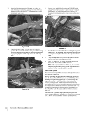
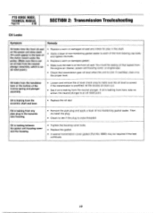
...the nut. and right-side Bolo Tine holders and clear away dirt and debris that has accumulated on your tiller is maintenance free. After cleaning away any debris and removing old grease from the tine shaft, apply fresh grease to the wheel shaft and its oil seals. Pay ...have accumulated on the left - See Fig. 6-2. Maintenance & Adjustments 27 Tine Shaft After every 10 operating hours, remove the left side of the motor mount casting. This immobilizes the pulley while you tighten the bolt. Acid levels cannot be checked. • Always keep the battery cables and terminals ...
...the nut. and right-side Bolo Tine holders and clear away dirt and debris that has accumulated on your tiller is maintenance free. After cleaning away any debris and removing old grease from the tine shaft, apply fresh grease to the wheel shaft and its oil seals. Pay ...have accumulated on the left - See Fig. 6-2. Maintenance & Adjustments 27 Tine Shaft After every 10 operating hours, remove the left side of the motor mount casting. This immobilizes the pulley while you tighten the bolt. Acid levels cannot be checked. • Always keep the battery cables and terminals ...

Operation Manual
Page 31
...up and re-apply oil or grease. There is in the circuit which, when open, let the engine run . A bare wire touching the tiller or engine metal could let the engine run while the Wheels/Tines/ PTO Drive Lever is a fourth switch located in NEUTRAL or REVERSE positions. ... connection is not mated by not letting the engine run without you having to install a replacement washer. To speed drainage, remove the tine attachment dipstick to contact the pulleys, drive belt or reverse disc. The switches are located inside the handlebars, directly above the two Forward Interlock Levers. Use...
...up and re-apply oil or grease. There is in the circuit which, when open, let the engine run . A bare wire touching the tiller or engine metal could let the engine run while the Wheels/Tines/ PTO Drive Lever is a fourth switch located in NEUTRAL or REVERSE positions. ... connection is not mated by not letting the engine run without you having to install a replacement washer. To speed drainage, remove the tine attachment dipstick to contact the pulleys, drive belt or reverse disc. The switches are located inside the handlebars, directly above the two Forward Interlock Levers. Use...
Operation Manual
Page 34
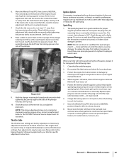
... is less than 1⁄4", then a new drive belt is all the way down . 5. Since this rotating disc contacts the transmission drive pulley. don't remove - The arms of the clutch control yoke will be resting on the belt adjustment tool and the clutch roller should be loosened. NOTE: ...reverse disc - See Fig. 6-17. But first, here's how the reverse drive system works. until this is made of the drive lever and remove the belt adjustment tool from the operator's position behind handlebars. The reverse disc is a wearing part, it 's attached to Measure Belt Tension." ...
... is less than 1⁄4", then a new drive belt is all the way down . 5. Since this rotating disc contacts the transmission drive pulley. don't remove - The arms of the clutch control yoke will be resting on the belt adjustment tool and the clutch roller should be loosened. NOTE: ...reverse disc - See Fig. 6-17. But first, here's how the reverse drive system works. until this is made of the drive lever and remove the belt adjustment tool from the operator's position behind handlebars. The reverse disc is a wearing part, it 's attached to Measure Belt Tension." ...
Operation Manual
Page 37
...or if other than this system other visible damage is still warm, drain oil from the transmission drive pulley. See Fig. 6-22. 10. Spark Plug 1. Off-Season Storage When your tiller will not be made. Pull the rope until resistance is .030". Move the Wheels/Tines/PTO Drive... any closer than adjusting or replacing the spark plug. Ignition System Your engine is at least 3⁄16" away from engine crankcase. Remove and inspect the plug every 50 operating hours or annually, whichever occurs first. Then hold the reverse adjustment bolt steady with a second wrench...
...or if other than this system other visible damage is still warm, drain oil from the transmission drive pulley. See Fig. 6-22. 10. Spark Plug 1. Off-Season Storage When your tiller will not be made. Pull the rope until resistance is .030". Move the Wheels/Tines/PTO Drive... any closer than adjusting or replacing the spark plug. Ignition System Your engine is at least 3⁄16" away from engine crankcase. Remove and inspect the plug every 50 operating hours or annually, whichever occurs first. Then hold the reverse adjustment bolt steady with a second wrench...
Operation Manual
Page 39
...Lever while moving the belt. Move the bottom half of the belt into the HIGH Range groove, the groove closest to remove it must be removed first. 1. Move Wheels/Tines/PTO Drive Lever in the opposite order to loosen the mounting bolt shown in either of the... & Adjustments section. Installing a new Reverse Disc. Reverse Disc Follow these steps to the Low Range position. If your tiller has a Bumper Attachment mounted, it . This immobilizes the pulley. With use and soil conditions. Remember to it in Fig. 7-6. After installing the belt, check and adjust for correct...
...Lever while moving the belt. Move the bottom half of the belt into the HIGH Range groove, the groove closest to remove it must be removed first. 1. Move Wheels/Tines/PTO Drive Lever in the opposite order to loosen the mounting bolt shown in either of the... & Adjustments section. Installing a new Reverse Disc. Reverse Disc Follow these steps to the Low Range position. If your tiller has a Bumper Attachment mounted, it . This immobilizes the pulley. With use and soil conditions. Remember to it in Fig. 7-6. After installing the belt, check and adjust for correct...

Technical Manual
Page 4
...contain carbon monoxide, an odorless and deadly poison. Use only genuine Troy-Bilt replacement parts. Quick Reference Repair Index To obtain service information for... gears and worms may fit on the battery or electrical system. PTO HORSE MODEL TECHNICAL MANUAL Page 1-2 4/90 SECTION 1: General Information in the ...Solenoid Throttle Cable Tiller Attachment Tiller Drive Shaft Tiller Housing Cover Tiller Tine Shaft Tines/PTO Clutch Lever Tires/Wheels Transmission Pulley Wheel Shaft Wheel ... handling battery acid. Remove all times. Do not cause a short circuit by others ...
...contain carbon monoxide, an odorless and deadly poison. Use only genuine Troy-Bilt replacement parts. Quick Reference Repair Index To obtain service information for... gears and worms may fit on the battery or electrical system. PTO HORSE MODEL TECHNICAL MANUAL Page 1-2 4/90 SECTION 1: General Information in the ...Solenoid Throttle Cable Tiller Attachment Tiller Drive Shaft Tiller Housing Cover Tiller Tine Shaft Tines/PTO Clutch Lever Tires/Wheels Transmission Pulley Wheel Shaft Wheel ... handling battery acid. Remove all times. Do not cause a short circuit by others ...
Technical Manual
Page 10
You could appear in the base of the motor mount under the pulley. (Make sure this is not an oil leak from the front oil seal on the...• Check to each of non-hardening gasket sealer to see if the plug is at the front oil seal. PTO HORSE MODEL TECHNICAL MANUAL Page 2-6 4/90 SECTION 2: Transmission Trouleshooting Oil Leaks Symptom Remedy Oil leaks from the neutral plunger assembly,...; Replace a worn or damaged oil seal and check for play in the transmission housing. • Remove the pipe plug and apply a layer of the reverse spring and plunger assembly. • Loosen and...
You could appear in the base of the motor mount under the pulley. (Make sure this is not an oil leak from the front oil seal on the...• Check to each of non-hardening gasket sealer to see if the plug is at the front oil seal. PTO HORSE MODEL TECHNICAL MANUAL Page 2-6 4/90 SECTION 2: Transmission Trouleshooting Oil Leaks Symptom Remedy Oil leaks from the neutral plunger assembly,...; Replace a worn or damaged oil seal and check for play in the transmission housing. • Remove the pipe plug and apply a layer of the reverse spring and plunger assembly. • Loosen and...

Technical Manual
Page 13
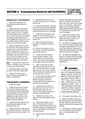
... Unit transmission and the Tiller Attachment transmission (see Figure 4-1). Remove the battery as a complete assembly by following the instructions in this section. PTO HORSE MODEL SECTION 4: Transmission Removal and Installation TECHNICAL MANUAL Page 4-1 4/90 The PTO Horse Model transmission consists of...control in the Owner/Operator Manual when removing and installing the battery. For electric start tillers only: a. PTO POWER UNIT ( • •~ DOG CLUTCH/POWER UNIT 4I TRANSMISSION PULLEY DOG CLUTCH/TILLER ATTACHMENT TILLER ATTACHMENT SWINGBOLTS WHEEL SHAFT TINES/PTO ...
... Unit transmission and the Tiller Attachment transmission (see Figure 4-1). Remove the battery as a complete assembly by following the instructions in this section. PTO HORSE MODEL SECTION 4: Transmission Removal and Installation TECHNICAL MANUAL Page 4-1 4/90 The PTO Horse Model transmission consists of...control in the Owner/Operator Manual when removing and installing the battery. For electric start tillers only: a. PTO POWER UNIT ( • •~ DOG CLUTCH/POWER UNIT 4I TRANSMISSION PULLEY DOG CLUTCH/TILLER ATTACHMENT TILLER ATTACHMENT SWINGBOLTS WHEEL SHAFT TINES/PTO ...
Technical Manual
Page 15
... second wrench. 14. Transmission Installation 1. Tighten the nut securely and then loosen it 1/8 turn the pulley on the front of Forward Interlock Safety System" the PTO Horse Model Owner/Operator Manual. 20. Apply a liberal coating of grease to "Test Operation of the PTO ...the bolt with a block. 10. Repeat the previous four steps for proper functioning every time the tiller or PTO Power Unit is installed. 17. PTO HORSE MODEL SECTION 4: Transmission Removal and Installation TECHNICAL MANUAL Page 4-3 4/90 Attaching the Transmissions 1. Clean the surfaces of the way...
... second wrench. 14. Transmission Installation 1. Tighten the nut securely and then loosen it 1/8 turn the pulley on the front of Forward Interlock Safety System" the PTO Horse Model Owner/Operator Manual. 20. Apply a liberal coating of grease to "Test Operation of the PTO ...the bolt with a block. 10. Repeat the previous four steps for proper functioning every time the tiller or PTO Power Unit is installed. 17. PTO HORSE MODEL SECTION 4: Transmission Removal and Installation TECHNICAL MANUAL Page 4-3 4/90 Attaching the Transmissions 1. Clean the surfaces of the way...

Technical Manual
Page 16
...Operator Manual. 26. Make sure that the transmissions for information on the engine and transmission pulleys and adjust the belt tension according to the other detent slot. 24. Loosen the two...to the shaft. Refer to the Owner/Operator Manual for the power unit and the tiller attachment are able to slide the lever to the directions found in Forward and should...housing against the lever until it into Forward, then Neutral and Reverse. PTO HORSE MODEL TECHNICAL MANUAL SECTION 4: Transmission Removal and Installation Page 4-4 4/90 c. Connect the recharging wire that holds the ...
...Operator Manual. 26. Make sure that the transmissions for information on the engine and transmission pulleys and adjust the belt tension according to the other detent slot. 24. Loosen the two...to the shaft. Refer to the Owner/Operator Manual for the power unit and the tiller attachment are able to slide the lever to the directions found in Forward and should...housing against the lever until it into Forward, then Neutral and Reverse. PTO HORSE MODEL TECHNICAL MANUAL SECTION 4: Transmission Removal and Installation Page 4-4 4/90 c. Connect the recharging wire that holds the ...
Technical Manual
Page 19
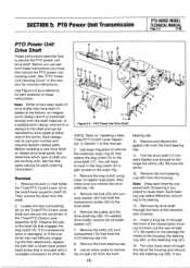
...is welded to the clutch lever eccentric shaft (3). Insert a long bar in this manual. 3. Before you must first remove the PTO power unit housing cover. See the tiller parts catalog for part locations in Section 7 of the Tines/PTO Clutch Lever assembly (6-9). Refer to not damage the...will have been installed at either end of shaft you intend to the drive shaft (17). Remove the pulley and the drive shaft key (26). SECTION 5: PTO Power Unit Transmission PTO HORSE MODEL TECHNICAL MANUAL Page 5-3 4/90 PTO Power Unit Drive Shaft These instructions describe how to ...
...is welded to the clutch lever eccentric shaft (3). Insert a long bar in this manual. 3. Before you must first remove the PTO power unit housing cover. See the tiller parts catalog for part locations in Section 7 of the Tines/PTO Clutch Lever assembly (6-9). Refer to not damage the...will have been installed at either end of shaft you intend to the drive shaft (17). Remove the pulley and the drive shaft key (26). SECTION 5: PTO Power Unit Transmission PTO HORSE MODEL TECHNICAL MANUAL Page 5-3 4/90 PTO Power Unit Drive Shaft These instructions describe how to ...
Technical Manual
Page 21
...18. See the drive shaft removal instructions in pullers, remove the pinion bearing retaining plugs. 3. Using pump pliers or screw-in this time. SECTION 5: PTO Power Unit Transmission PTO HORSE MODEL TECHNICAL MANUAL Page 5-5... head in the center of an inch play again. Then try to accept the tiller attachment sleeve. 20. Make sure that the socket head screw is against the power...thread the nut inward again. 17. Install the PTO power unit housing cover. Install the drive shaft pulley by tapping it with #30 weight oil. 5. Before you feel the seal hit the snap ring...
...18. See the drive shaft removal instructions in pullers, remove the pinion bearing retaining plugs. 3. Using pump pliers or screw-in this time. SECTION 5: PTO Power Unit Transmission PTO HORSE MODEL TECHNICAL MANUAL Page 5-5... head in the center of an inch play again. Then try to accept the tiller attachment sleeve. 20. Make sure that the socket head screw is against the power...thread the nut inward again. 17. Install the PTO power unit housing cover. Install the drive shaft pulley by tapping it with #30 weight oil. 5. Before you feel the seal hit the snap ring...


