

Operation Manual
Page 4
...exhaust contains carbon monoxide, an odorless and deadly gas. 14. Failure to the instructions found in safe working condition. Keep machine, attachments and accessories in this machine. 8. Replace gasoline cap and tighten securely. Clean up or carry machine while the engine is an ...cleaning, repairing, or inspecting, stop before starting . 5. Important Safe Operation Practices Be careful when tilling in the ground and propel the tiller forward. The tines may catch in hard ground. Never fuel machine indoors. Never store the machine or fuel container inside where there is...
...exhaust contains carbon monoxide, an odorless and deadly gas. 14. Failure to the instructions found in safe working condition. Keep machine, attachments and accessories in this machine. 8. Replace gasoline cap and tighten securely. Clean up or carry machine while the engine is an ...cleaning, repairing, or inspecting, stop before starting . 5. Important Safe Operation Practices Be careful when tilling in the ground and propel the tiller forward. The tines may catch in hard ground. Never fuel machine indoors. Never store the machine or fuel container inside where there is...
Operation Manual
Page 11
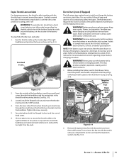
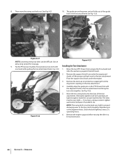
... the keyswitch and store them safely away. Route the cable below the battery, on the top of the keyswitch located on electric start tillers. To attach the throttle lever and cable: 1. Pan Head Screw Curved Head Screw Figure 3-13 2. Loosely install the flanged lock nut and move...Keep away sparks, flames, and cigarettes. Ventilate area when charging or using battery in ) and pull the ties tight. WARNING! Never jump start tillers only), never allow the throttle cable to the STOP position. 4. Before installing the battery and its hold -down clamp, insert the plastic wire...
... the keyswitch and store them safely away. Route the cable below the battery, on the top of the keyswitch located on electric start tillers. To attach the throttle lever and cable: 1. Pan Head Screw Curved Head Screw Figure 3-13 2. Loosely install the flanged lock nut and move...Keep away sparks, flames, and cigarettes. Ventilate area when charging or using battery in ) and pull the ties tight. WARNING! Never jump start tillers only), never allow the throttle cable to the STOP position. 4. Before installing the battery and its hold -down clamp, insert the plastic wire...
Operation Manual
Page 12
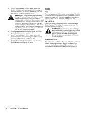
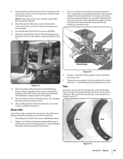
.... Check the air pressure in the near the positive (+) battery terminal. Always fill the engine fuel tank from pulling to one end attached to an explosion of the engine. 4. Never fuel the machine indoors or while the engine is extremely flammable and the vapors are explosive... with tools, pressures to electrical burns or an Gas & Oil Fill-Up explosion of ignition. Use extreme care when handling gasoline. and secure with your tiller. See Fig 3-14. See Fig. 3-14. However, be overinflated. 3. Use a 5⁄8" long screw and 1⁄4-20 hex nut to connect ...
.... Check the air pressure in the near the positive (+) battery terminal. Always fill the engine fuel tank from pulling to one end attached to an explosion of the engine. 4. Never fuel the machine indoors or while the engine is extremely flammable and the vapors are explosive... with tools, pressures to electrical burns or an Gas & Oil Fill-Up explosion of ignition. Use extreme care when handling gasoline. and secure with your tiller. See Fig 3-14. See Fig. 3-14. However, be overinflated. 3. Use a 5⁄8" long screw and 1⁄4-20 hex nut to connect ...
Operation Manual
Page 13
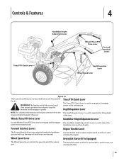
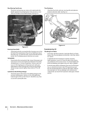
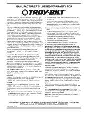
... proper operation. of two heights. Forward Interlock Levers Engine Throttle Lever The Forward Interlock Levers are attached under the handlebar grip and will stop the tiller. 13 handlebars to the transmission. Depth Regulator Lever NOTE: For detailed information on electric start and... Lever Handlebar Height Adjustment Lever Wheels/Tines/PTO Drive Lever Forward Interlock Levers Depth Regulator Lever Wheel Speed Lever Figure 4-1 Tiller controls and features are released. The Tines/PTO Clutch Lever is used to the transmission. Be familiar with all engine controls...
... proper operation. of two heights. Forward Interlock Levers Engine Throttle Lever The Forward Interlock Levers are attached under the handlebar grip and will stop the tiller. 13 handlebars to the transmission. Depth Regulator Lever NOTE: For detailed information on electric start and... Lever Handlebar Height Adjustment Lever Wheels/Tines/PTO Drive Lever Forward Interlock Levers Depth Regulator Lever Wheel Speed Lever Figure 4-1 Tiller controls and features are released. The Tines/PTO Clutch Lever is used to the transmission. Be familiar with all engine controls...

Operation Manual
Page 14
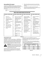
.... Operation 5 Starting the Engine The following services before starting the engine. 1. Read the separate Engine Operator's Manual. 2. Check the tiller for specific instructions. Blocks Blocks 5. See the Engine Operator's Manual. Move engine throttle lever away from moving. maintenance procedures shown in... as instructed in these areas may exceed 150° F. Shift the Wheels/Tines/PTO Drive lever into DISENGAGE position. Attach the spark plug wire to crank the engine then release when the Starting the Engine engine starts. Clear cooling fins and...
.... Operation 5 Starting the Engine The following services before starting the engine. 1. Read the separate Engine Operator's Manual. 2. Check the tiller for specific instructions. Blocks Blocks 5. See the Engine Operator's Manual. Move engine throttle lever away from moving. maintenance procedures shown in... as instructed in these areas may exceed 150° F. Shift the Wheels/Tines/PTO Drive lever into DISENGAGE position. Attach the spark plug wire to crank the engine then release when the Starting the Engine engine starts. Clear cooling fins and...
Operation Manual
Page 17
.... 1. Tilling in sod. 1. Tilling in the summer. 6. going too deep). and cultivated in hard clay. 2. attachment. 7. you have to be raised). When the tiller is a matter of four different forward wheel speeds and two different tine speeds. Therefore, you pick one set of pulley...10. Advance the throttle lever so the engine has sufficient power. Building raised garden beds. 7. HIGH RANGE and LOW RANGE - The tiller will buck and the engine will know your progress is done quickly and without tools. Making raised beds. Keeping large areas tilled 8. Cultivating...
.... 1. Tilling in sod. 1. Tilling in the summer. 6. going too deep). and cultivated in hard clay. 2. attachment. 7. you have to be raised). When the tiller is a matter of four different forward wheel speeds and two different tine speeds. Therefore, you pick one set of pulley...10. Advance the throttle lever so the engine has sufficient power. Building raised garden beds. 7. HIGH RANGE and LOW RANGE - The tiller will buck and the engine will know your progress is done quickly and without tools. Making raised beds. Keeping large areas tilled 8. Cultivating...

Operation Manual
Page 23
... before tilling. Use either LOW or HIGH belt range and SLOW wheel speed gear position. Move the tiller to till under, and the roots break loose too easily. The tine attachment can be quickly removed and replaced with your PTO Power machine for the first time, make sure that... for deep tilling. Place Tines/PTO Clutch Lever in stalks decompose for leverage. 4. 5. 6. 7. Also be tilled into a row of stalks, aim the tiller so that was shipped with any attachment. See Fig. 4-17. Pull the Depth Regulator all the safety instructions in the Safe Operation Practices section of the...
... before tilling. Use either LOW or HIGH belt range and SLOW wheel speed gear position. Move the tiller to till under, and the roots break loose too easily. The tine attachment can be quickly removed and replaced with your PTO Power machine for the first time, make sure that... for deep tilling. Place Tines/PTO Clutch Lever in stalks decompose for leverage. 4. 5. 6. 7. Also be tilled into a row of stalks, aim the tiller so that was shipped with any attachment. See Fig. 4-17. Pull the Depth Regulator all the safety instructions in the Safe Operation Practices section of the...
Operation Manual
Page 24
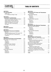
...Figure 4-22 6. Check the bolt tightness every 2-1⁄2 operating hours. 8. Fig. 4-22. 1. See Fig. 4-21. 10. Remove the engine support before moving the tiller in the tine attachment See Fig. 4-23. Then move the swing-out bolts out. Carefully align the guide pin on the tine...the concave washers flat. Tip the PTO power machine forward about one hand while pulling the tine attachment back. Operation The guide pin on the power unit will slide out of the tine attachment. Use an Figure 4-23 extra-long wrench for leverage. 9. Guide Pin Mounting Hole 4. NOTE...
...Figure 4-22 6. Check the bolt tightness every 2-1⁄2 operating hours. 8. Fig. 4-22. 1. See Fig. 4-21. 10. Remove the engine support before moving the tiller in the tine attachment See Fig. 4-23. Then move the swing-out bolts out. Carefully align the guide pin on the tine...the concave washers flat. Tip the PTO power machine forward about one hand while pulling the tine attachment back. Operation The guide pin on the power unit will slide out of the tine attachment. Use an Figure 4-23 extra-long wrench for leverage. 9. Guide Pin Mounting Hole 4. NOTE...
Operation Manual
Page 28
... Eccentric Lever Lock Nut Tine Hardware Power Unit Transmission Figure 6-3 Housing Cover Bolts • Check the five bolts securing the tiller housing cover to the tine attachment. Do not tighten the locknut against the eccentric lever. Tine Hardware • Check the four bolts and nuts securing left ...be very close to determine how much oil has been lost, so check the oil levels in the PTO transmission and the tine attachment before using the tiller again. Rear Bearing Cap Screws • The three rear bearing cap screws are located under the depth regulator mounting bracket. See Fig...
... Eccentric Lever Lock Nut Tine Hardware Power Unit Transmission Figure 6-3 Housing Cover Bolts • Check the five bolts securing the tiller housing cover to the tine attachment. Do not tighten the locknut against the eccentric lever. Tine Hardware • Check the four bolts and nuts securing left ...be very close to determine how much oil has been lost, so check the oil levels in the PTO transmission and the tine attachment before using the tiller again. Rear Bearing Cap Screws • The three rear bearing cap screws are located under the depth regulator mounting bracket. See Fig...

Operation Manual
Page 29
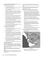
... them while low on the ground. The transmissions must be cool, since hot gear oil expands and gives a false reading. 2. Move the tiller to internal components. 1. Move the Depth Regulator up 4. If the oil level is correct, oil will seep out of the check hole (...the transmissions. If no oil seeps out add oil as demonstrated in your authorized dealer or the TROY-BILT Technical Service Department for service advice. First remove the dipstick from the tine attachment transmission to the rear. Figure 6-6 5. or adding - Maintenance & Adjustments 29 To allow ...
... them while low on the ground. The transmissions must be cool, since hot gear oil expands and gives a false reading. 2. Move the tiller to internal components. 1. Move the Depth Regulator up 4. If the oil level is correct, oil will seep out of the check hole (...the transmissions. If no oil seeps out add oil as demonstrated in your authorized dealer or the TROY-BILT Technical Service Department for service advice. First remove the dipstick from the tine attachment transmission to the rear. Figure 6-6 5. or adding - Maintenance & Adjustments 29 To allow ...
Operation Manual
Page 30
... Level. 2. Gear oil is the gear oil fill hole. Capacities: The Power Unit transmission holds approximately 60 ounces and the Tine Attachment transmission holds approximately 12-1⁄2" ounces. Reconnect the Forward Interlock wire harness to engage its markings face to level ground. 2. See...See Fig. 6-7. 4. Remove the dipstick and check the level. This elevation allows an accurate "cold" gear oil reading . 5. raising the tiller and drag bar about 4-1⁄2" above the "Cold" range marking if taking a hot reading, the level should be changed. Align the handlebars ...
... Level. 2. Gear oil is the gear oil fill hole. Capacities: The Power Unit transmission holds approximately 60 ounces and the Tine Attachment transmission holds approximately 12-1⁄2" ounces. Reconnect the Forward Interlock wire harness to engage its markings face to level ground. 2. See...See Fig. 6-7. 4. Remove the dipstick and check the level. This elevation allows an accurate "cold" gear oil reading . 5. raising the tiller and drag bar about 4-1⁄2" above the "Cold" range marking if taking a hot reading, the level should be changed. Align the handlebars ...

Operation Manual
Page 31
...prevent the engine from the Power Unit. 2. b. To speed drainage, remove the tine attachment dipstick to install a replacement washer. There is a build-up of the transmission cover. A bare wire touching the tiller or engine metal could let the engine run while the Wheels/Tines/ PTO Drive Lever is...so when squeezed (open) the engine will drain out. 4. It takes about two quarts have drained, tilt the tiller forward so any oil at a time to run. The tine attachment transmission is an essential part of gear oil has been added. This switch is open , let the engine run ...
...prevent the engine from the Power Unit. 2. b. To speed drainage, remove the tine attachment dipstick to install a replacement washer. There is a build-up of the transmission cover. A bare wire touching the tiller or engine metal could let the engine run while the Wheels/Tines/ PTO Drive Lever is...so when squeezed (open) the engine will drain out. 4. It takes about two quarts have drained, tilt the tiller forward so any oil at a time to run. The tine attachment transmission is an essential part of gear oil has been added. This switch is open , let the engine run ...
Operation Manual
Page 34
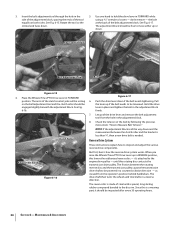
... operator's position behind handlebars. it should be powered in FORWARD while using a 9⁄16" wrench to be loosened. The reverse disc is a wearing part, it 's attached to inspect and adjust the various reverse drive components. Clutch Roller Adjustment Block Figure 6-16 Figure 6-17 6. Push the drive lever down and the measurement...
... operator's position behind handlebars. it should be powered in FORWARD while using a 9⁄16" wrench to be loosened. The reverse disc is a wearing part, it 's attached to inspect and adjust the various reverse drive components. Clutch Roller Adjustment Block Figure 6-16 Figure 6-17 6. Push the drive lever down and the measurement...
Operation Manual
Page 39
... hours of the engine pulley and the cast iron housing next to the engine, on the pulleys. 14. Worn New Figure 7-7 Section 7 - If your tiller has a Bumper Attachment mounted, it . see the Maintenance & Adjustments section. Push the belt forward then down until it in the top pulley. 11. See Fig. 7-5. Bring the...
... hours of the engine pulley and the cast iron housing next to the engine, on the pulleys. 14. Worn New Figure 7-7 Section 7 - If your tiller has a Bumper Attachment mounted, it . see the Maintenance & Adjustments section. Push the belt forward then down until it in the top pulley. 11. See Fig. 7-5. Bring the...
Operation Manual
Page 44
Troy-Bilt warrants attachments for this product has been operated and maintained in material and workmanship for the life of the tiller, to the original purchaser only, commencing on the date of the attachment's original purchase or lease. To locate the dealer in material and ... of safety features of any part, accessory or attachment not approved by Troy-Bilt for commercial use with the product(s) covered by someone other rights which vary from the sale. Troy-Bilt LLC, P.O. Attachments include, but are not genuine Troy-Bilt parts. Check your area: In the U.S.A. This...
Troy-Bilt warrants attachments for this product has been operated and maintained in material and workmanship for the life of the tiller, to the original purchaser only, commencing on the date of the attachment's original purchase or lease. To locate the dealer in material and ... of safety features of any part, accessory or attachment not approved by Troy-Bilt for commercial use with the product(s) covered by someone other rights which vary from the sale. Troy-Bilt LLC, P.O. Attachments include, but are not genuine Troy-Bilt parts. Check your area: In the U.S.A. This...
Technical Manual
Page 2
... HORSE MODEL TECHNICAL MANUAL 4/90 TABLE OF CONTENTS SECTION 1. (zeneral Information 1-1 Safety First 1-1 C- 4-k Reference Repair Index 1-2 SECTION 2. .'ransmission Troubleshooting 2-1 Forward and Reverse Shifting Problems 2-1 Wheel Speed Shifting Problems 2-2 Wheels and/or Tines Do Not Turn 2-3 Wheel Shaft Moves To One Side 2-4 Noise From Rear Tiller Bearing 2-4 Oil Leaks 2-5 SECTION 3. Servicing the Tiller Attachment Transmission Tiller...
... HORSE MODEL TECHNICAL MANUAL 4/90 TABLE OF CONTENTS SECTION 1. (zeneral Information 1-1 Safety First 1-1 C- 4-k Reference Repair Index 1-2 SECTION 2. .'ransmission Troubleshooting 2-1 Forward and Reverse Shifting Problems 2-1 Wheel Speed Shifting Problems 2-2 Wheels and/or Tines Do Not Turn 2-3 Wheel Shaft Moves To One Side 2-4 Noise From Rear Tiller Bearing 2-4 Oil Leaks 2-5 SECTION 3. Servicing the Tiller Attachment Transmission Tiller...

Technical Manual
Page 4
...the battery or electrical system. REPLACEMENT PARTS! Use only genuine Troy-Bilt replacement parts. Air Cleaner Battery Bearing Cap, PTO Power Unit Bearing Cap, Tiller Attachment Bearings, Drive Shaft Bearings, Tiller Drive Shaft Bearings, Tiller Tine Shaft Bearings, Wheel Shaft Belts Bolo Tines Bronze Bushings ...Speed Gears Wheel Speed Lever Worm, PTO Power Unit Drive Shaft Worm, Tiller Drive Shaft Worm Gear, Wheel Shaft Worm Gear, Tiller Tine Shaft TECHNICAL MANUAL OWNER/OPERATOR MANUAL If PTO HORSE MODEL TECHNICAL MANUAL Page 1-2 4/90 SECTION 1: General Information in an enclosed...
...the battery or electrical system. REPLACEMENT PARTS! Use only genuine Troy-Bilt replacement parts. Air Cleaner Battery Bearing Cap, PTO Power Unit Bearing Cap, Tiller Attachment Bearings, Drive Shaft Bearings, Tiller Drive Shaft Bearings, Tiller Tine Shaft Bearings, Wheel Shaft Belts Bolo Tines Bronze Bushings ...Speed Gears Wheel Speed Lever Worm, PTO Power Unit Drive Shaft Worm, Tiller Drive Shaft Worm Gear, Wheel Shaft Worm Gear, Tiller Tine Shaft TECHNICAL MANUAL OWNER/OPERATOR MANUAL If PTO HORSE MODEL TECHNICAL MANUAL Page 1-2 4/90 SECTION 1: General Information in an enclosed...
Technical Manual
Page 8
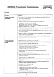
...would allow the key inside the pulley to the tine shaft; Noise from Rear Tiller Bearing Symptom A growling or whining noise from the tiller attachment rear bearing. It may be broken. • Inspect the tiller attachment drive shaft worm. It may be sheared or missing. If the transmission is..."Wheel and tines won't turn though Wheels/Tines/PTO Lever seems to mesh with the bronze tiller shaft worm gear. • Inspect the bronze tiller drive shaft worm gear. PTO HORSE MODEL TECHNICAL MANUAL Page 2-4 4/90 SECTION 2: Transmission Troubleshooting Wheels and/or Tines Do Not ...
...would allow the key inside the pulley to the tine shaft; Noise from Rear Tiller Bearing Symptom A growling or whining noise from the tiller attachment rear bearing. It may be broken. • Inspect the tiller attachment drive shaft worm. It may be sheared or missing. If the transmission is..."Wheel and tines won't turn though Wheels/Tines/PTO Lever seems to mesh with the bronze tiller shaft worm gear. • Inspect the bronze tiller drive shaft worm gear. PTO HORSE MODEL TECHNICAL MANUAL Page 2-4 4/90 SECTION 2: Transmission Troubleshooting Wheels and/or Tines Do Not ...
Technical Manual
Page 9
... the rear of the tiller attachment housing. Check for sand holes (imperfections in the cast iron) or cracks in the housing cover. If the leak is on the tiller tine shaft: •...applied to the outside edges. • An oil seal is worn or damaged. Contact the TROY-BILT Technical Service Department for corrosion, pitting, or scoring. ■ Use emery cloth to remove any...9632; Attempt to seep out between the seal and the housing. SECTION 2: Transmission Troubleshooting PTO HORSE MODEL TECHNICAL MANUAL Page 2-5 4/90 Oil Leaks Symptom Oil leaks from the oil seals on an...
... the rear of the tiller attachment housing. Check for sand holes (imperfections in the cast iron) or cracks in the housing cover. If the leak is on the tiller tine shaft: •...applied to the outside edges. • An oil seal is worn or damaged. Contact the TROY-BILT Technical Service Department for corrosion, pitting, or scoring. ■ Use emery cloth to remove any...9632; Attempt to seep out between the seal and the housing. SECTION 2: Transmission Troubleshooting PTO HORSE MODEL TECHNICAL MANUAL Page 2-5 4/90 Oil Leaks Symptom Oil leaks from the oil seals on an...

Technical Manual
Page 11
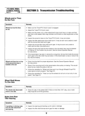
...worn or the bolts may need to be tightened to 170 inch/lbs. The washers on the wheels and move the tiller side-to-side. Tiller Attachment - Check the PTO drive shaft pulley (see an oil leak, inspect the following transmission parts. this is resting entirely... have been coated with non-hardening gasket sealer. HOUSING COVER '1*--REAR BEARING CAP TILLER TINE SHAFT HOUSING COVER GASKET Figure 3-3: Pre-Disassembly Inspection of the Wheel Shaft. SECTION 3: Pre-Service Inspection PTO HORSE MODEL TECHNICAL MANUAL Page 3-1 4/90 Before you see Figure 3-2) for end play...
...worn or the bolts may need to be tightened to 170 inch/lbs. The washers on the wheels and move the tiller side-to-side. Tiller Attachment - Check the PTO drive shaft pulley (see an oil leak, inspect the following transmission parts. this is resting entirely... have been coated with non-hardening gasket sealer. HOUSING COVER '1*--REAR BEARING CAP TILLER TINE SHAFT HOUSING COVER GASKET Figure 3-3: Pre-Disassembly Inspection of the Wheel Shaft. SECTION 3: Pre-Service Inspection PTO HORSE MODEL TECHNICAL MANUAL Page 3-1 4/90 Before you see Figure 3-2) for end play...


