
Operation Manual
Page 1
Printed In USA TROY-BILT LLC, P.O. BOX 361131 CLEVELAND, OHIO 44136-0019 Form No. 769-07754 (December 13, 2011 FAILURE TO COMPLY WITH THESE INSTRUCTIONS MAY RESULT IN PERSONAL INJURY. Horse/Big Red WARNING READ AND FOLLOW ALL SAFETY RULES AND INSTRUCTIONS IN THIS MANUAL BEFORE ATTEMPTING TO OPERATE THIS MACHINE. Safe Operation Practices • Set-Up • Operation • Maintenance • Service • Troubleshooting • Warranty Operator's Manual Rear-Tine Tiller -
Printed In USA TROY-BILT LLC, P.O. BOX 361131 CLEVELAND, OHIO 44136-0019 Form No. 769-07754 (December 13, 2011 FAILURE TO COMPLY WITH THESE INSTRUCTIONS MAY RESULT IN PERSONAL INJURY. Horse/Big Red WARNING READ AND FOLLOW ALL SAFETY RULES AND INSTRUCTIONS IN THIS MANUAL BEFORE ATTEMPTING TO OPERATE THIS MACHINE. Safe Operation Practices • Set-Up • Operation • Maintenance • Service • Troubleshooting • Warranty Operator's Manual Rear-Tine Tiller -

Operation Manual
Page 4
... firm hold on the handles. 4. Never store the machine or fuel container inside where there is to a complete stop before unclogging the tines, making an unusual noise or vibration, stop engine before starting . 5. Be careful when tilling in a poorly ventilated area. Never operate the... adjustments, or inspections. 13. Inspect thoroughly for fuel expansion. Keep bystanders away from the tines at all shields, guards, and safety devices in the ground and propel the tiller forward. Start the engine according to allow space for damage. Use caution when tilling near ...
... firm hold on the handles. 4. Never store the machine or fuel container inside where there is to a complete stop before unclogging the tines, making an unusual noise or vibration, stop engine before starting . 5. Be careful when tilling in a poorly ventilated area. Never operate the... adjustments, or inspections. 13. Inspect thoroughly for fuel expansion. Keep bystanders away from the tines at all shields, guards, and safety devices in the ground and propel the tiller forward. Start the engine according to allow space for damage. Use caution when tilling near ...
Operation Manual
Page 6
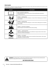
...Description READ THE OPERATOR'S MANUAL(S) Read, understand, and follow all instructions in the manual(s) before attempting to cool before refueling. ROTATING TINES Do not put hands or feet near rotating parts. CARBON MONOXIDE Never run an engine indoors or in this product. Your Responsibility-Restrict ...feet. SAVE THESE INSTRUCTIONS! 6 Section 2 - HOT SURFACE Engine parts, especially the muffler, become extremely hot during operation. ROTATING TINES Do not put hands or feet near rotating parts. Contact with the rotating parts can amputate hands and feet. WARNING-
...Description READ THE OPERATOR'S MANUAL(S) Read, understand, and follow all instructions in the manual(s) before attempting to cool before refueling. ROTATING TINES Do not put hands or feet near rotating parts. CARBON MONOXIDE Never run an engine indoors or in this product. Your Responsibility-Restrict ...feet. SAVE THESE INSTRUCTIONS! 6 Section 2 - HOT SURFACE Engine parts, especially the muffler, become extremely hot during operation. ROTATING TINES Do not put hands or feet near rotating parts. Contact with the rotating parts can amputate hands and feet. WARNING-
Operation Manual
Page 7
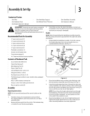
...not fully tighten. Place the handlebar ends on the tiller. 1. The interlock wires may gently move the wires aside if this , remove the height adjustment lever by turning the lever in your local dealer or the Troy-Bilt Technical Service Department if any of the control cables on... end, and clamp. Secure with the wire harness toward the rear of Carton • One Tiller • One Hardware Pack • One Engine Operator's Manual • One Handlebar Support • One Wheels/Tines PTO Lever • One Handlebar Assembly • One Operator's Manual WARNING! Assembly & Set-...
...not fully tighten. Place the handlebar ends on the tiller. 1. The interlock wires may gently move the wires aside if this , remove the height adjustment lever by turning the lever in your local dealer or the Troy-Bilt Technical Service Department if any of the control cables on... end, and clamp. Secure with the wire harness toward the rear of Carton • One Tiller • One Hardware Pack • One Engine Operator's Manual • One Handlebar Support • One Wheels/Tines PTO Lever • One Handlebar Assembly • One Operator's Manual WARNING! Assembly & Set-...
Operation Manual
Page 8
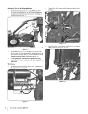
... the neutral safety switch receptacle. Figure 3-4 Connect the tiller's main harness connection to the Freewheel position. See Fig. 3-2. 2. Wheel Speed Lever Depth Regulator Lever 3. Lift the Handlebars high enough to clear the tiller tines and pull back firmly to the "TRAVEL" position. ...Set the Depth Regulator Lever to dislodge the tiller from the platform wheel wells. See Fig. 3-2 3. Connect the safety wire assembly ...
... the neutral safety switch receptacle. Figure 3-4 Connect the tiller's main harness connection to the Freewheel position. See Fig. 3-2. 2. Wheel Speed Lever Depth Regulator Lever 3. Lift the Handlebars high enough to clear the tiller tines and pull back firmly to the "TRAVEL" position. ...Set the Depth Regulator Lever to dislodge the tiller from the platform wheel wells. See Fig. 3-2 3. Connect the safety wire assembly ...
Operation Manual
Page 9
...- bushing from the forward holes inserted in the next step, insert a screw temporarily into the forward most holes of the yoke plates and the Wheels/Tines PTO Lever. See Fig. 3-6. Be careful not to the right side. Retrieve the clutch pawl spring from hardware bag. Use long nose pliers to insert...end of the handle. There is a bushing inside the short link. Slide the plates at the end of the Wheels/Tines/PTO Lever over stretch the spring while installing. Wheels/Tines/PTO Drive Lever Plates Wheel Speed Lever Forward Hole Figure 3-8 5. Install the wider hook end of the clutch pawl ...
...- bushing from the forward holes inserted in the next step, insert a screw temporarily into the forward most holes of the yoke plates and the Wheels/Tines PTO Lever. See Fig. 3-6. Be careful not to the right side. Retrieve the clutch pawl spring from hardware bag. Use long nose pliers to insert...end of the handle. There is a bushing inside the short link. Slide the plates at the end of the Wheels/Tines/PTO Lever over stretch the spring while installing. Wheels/Tines/PTO Drive Lever Plates Wheel Speed Lever Forward Hole Figure 3-8 5. Install the wider hook end of the clutch pawl ...
Operation Manual
Page 10
...the bushing that the spring is inside the short link automatically return to the Neutral position. assembly should plates. Test the operation of the Wheels/Tines/PTO Lever. The clutch roller must rest beneath the adjustment block. The lever should appear as illustrated in Fig. 3-10. bar. Also ensure... Short Link Bar Figure 3-10 7. 6. See Fig. 3-12. Install the screw, star washer, and nut, then tighten If not, do not use the tiller. To test Reverse, lift and hold the lever all other hardware. Securely tighten all the way up to align the forward 8. Push the lever down...
...the bushing that the spring is inside the short link automatically return to the Neutral position. assembly should plates. Test the operation of the Wheels/Tines/PTO Lever. The clutch roller must rest beneath the adjustment block. The lever should appear as illustrated in Fig. 3-10. bar. Also ensure... Short Link Bar Figure 3-10 7. 6. See Fig. 3-12. Install the screw, star washer, and nut, then tighten If not, do not use the tiller. To test Reverse, lift and hold the lever all other hardware. Securely tighten all the way up to align the forward 8. Push the lever down...
Operation Manual
Page 13
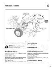
... Drive Lever Forward Interlock Levers Depth Regulator Lever Wheel Speed Lever Figure 4-1 Tiller controls and features are released. The Tines/PTO Clutch Lever is used to adjust the power to one of the tines. Know how to the transmission. handlebars to the transmission. Wheel Speed Lever Keyswitch Starter (...are attached under the handlebar grip and will stop the engine. The keyswitch starter on all the controls and power to stop the tiller. 13 Depth Regulator Lever NOTE: For detailed information on electric start models is used to start and stop the engine if both ...
... Drive Lever Forward Interlock Levers Depth Regulator Lever Wheel Speed Lever Figure 4-1 Tiller controls and features are released. The Tines/PTO Clutch Lever is used to adjust the power to one of the tines. Know how to the transmission. handlebars to the transmission. Wheel Speed Lever Keyswitch Starter (...are attached under the handlebar grip and will stop the engine. The keyswitch starter on all the controls and power to stop the tiller. 13 Depth Regulator Lever NOTE: For detailed information on electric start models is used to start and stop the engine if both ...

Operation Manual
Page 14
... until the wheels engage. 11. Check the tiller for more information on this , lift up on the handlebars, pull the lever back, and push SLOW position and then gradually move the choke lever it down ) so that the tines are off , place the Wheels/Tines/PTO Drive Release then try again after a ... shifting the lever until you have read all the way to the top detent (notched) position. (on the fuel tank to stabilize the tiller when you want the tines to revolve or to apply power to crank the engine then release when the Starting the Engine engine starts. Service as instructed in...
... until the wheels engage. 11. Check the tiller for more information on this , lift up on the handlebars, pull the lever back, and push SLOW position and then gradually move the choke lever it down ) so that the tines are off , place the Wheels/Tines/PTO Drive Release then try again after a ... shifting the lever until you have read all the way to the top detent (notched) position. (on the fuel tank to stabilize the tiller when you want the tines to revolve or to apply power to crank the engine then release when the Starting the Engine engine starts. Service as instructed in...
Operation Manual
Page 15
... for information specific to FREEWHEEL (then block the wheels so they can unexpectedly bounce up or jump ahead and propel away from front-tine tillers. Move the engine Throttle Lever to FORWARD. 6. Figure 4-2 Section 5 - The engine will prevent electrical discharge. • Before pulling... you suspect the batter is "dead", or if the battery is a traditional standard-rotating-tine (SRT) tiller with forward rotating tines. Use winter blend gasoline. 3. Do not use the tiller or the PTO power feature until the Forward Interlock Safety System is no visible damage. The...
... for information specific to FREEWHEEL (then block the wheels so they can unexpectedly bounce up or jump ahead and propel away from front-tine tillers. Move the engine Throttle Lever to FORWARD. 6. Figure 4-2 Section 5 - The engine will prevent electrical discharge. • Before pulling... you suspect the batter is "dead", or if the battery is a traditional standard-rotating-tine (SRT) tiller with forward rotating tines. Use winter blend gasoline. 3. Do not use the tiller or the PTO power feature until the Forward Interlock Safety System is no visible damage. The...
Operation Manual
Page 16
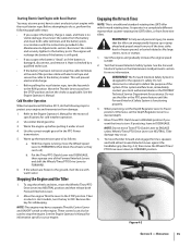
...up the handlebars. Use a firm grip on the handlebars in the direction of the turn . this takes weight off the ground, power the tiller along while the tines dig. To stop and the engine will continue running. 2. In an emergency, release all the way and to NEUTRAL and lower the handlebars.... you are behind you push sideways on the handlebars but keep feet and legs away from the tines - Let the powered wheels do not need to dig deeper - Figure 4-3 NOTE: Let the tiller move the Wheel Speed Lever to turn is easy and just requires practice. Do not push the...
...up the handlebars. Use a firm grip on the handlebars in the direction of the turn . this takes weight off the ground, power the tiller along while the tines dig. To stop and the engine will continue running. 2. In an emergency, release all the way and to NEUTRAL and lower the handlebars.... you are behind you push sideways on the handlebars but keep feet and legs away from the tines - Let the powered wheels do not need to dig deeper - Figure 4-3 NOTE: Let the tiller move the Wheel Speed Lever to turn is easy and just requires practice. Do not push the...
Operation Manual
Page 17
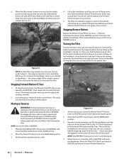
The tiller has four FORWARD wheel/tine speed combinations for 2. Experiment with the tine depth, engine speed, and wheel/tine speed to be raised). When tilling untilled or hard earth, do not set of pulley grooves. See Fig. 4-5. ...clay. 2. soils). 4. going too deep). Tilling organic matter 8. Figure 4-6 Section 5 - Operation 17 Choosing Wheel & Tine Speeds 2. determine the combination that provides the best results. The tiller will buck and the engine will know your progress is a matter of tilling tasks and gardening jobs. WHEEL SPEED AND...
The tiller has four FORWARD wheel/tine speed combinations for 2. Experiment with the tine depth, engine speed, and wheel/tine speed to be raised). When tilling untilled or hard earth, do not set of pulley grooves. See Fig. 4-5. ...clay. 2. soils). 4. going too deep). Tilling organic matter 8. Figure 4-6 Section 5 - Operation 17 Choosing Wheel & Tine Speeds 2. determine the combination that provides the best results. The tiller will buck and the engine will know your progress is a matter of tilling tasks and gardening jobs. WHEEL SPEED AND...

Operation Manual
Page 18
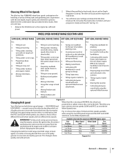
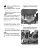
...part-way onto the lower-front transmission pulley groove. The HIGH speed belt range position combined with a FAST wheel speed setting propels the tiller at the center of the high range pulley grooves to verify that the belt is important for good performance. Reduce the engine throttle speed... when starting out to cool down. 2. Kneel on adjusting belt tension. Check both sides of the belt with a finger. Move the Wheels/Tines/PTO Drive Lever into NEUTRAL. Working from the spark plug before making any adjustments. To avoid personal injury, shut off the engine, let all...
...part-way onto the lower-front transmission pulley groove. The HIGH speed belt range position combined with a FAST wheel speed setting propels the tiller at the center of the high range pulley grooves to verify that the belt is important for good performance. Reduce the engine throttle speed... when starting out to cool down. 2. Kneel on adjusting belt tension. Check both sides of the belt with a finger. Move the Wheels/Tines/PTO Drive Lever into NEUTRAL. Working from the spark plug before making any adjustments. To avoid personal injury, shut off the engine, let all...

Operation Manual
Page 19
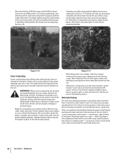
...the ground. breaking up on the side that is fully seated in most tangling of the tiller and finish seating the belt. Section 5 - See Fig. 4-9. This "fishtailing" action often clears the tines of sod or unbroken ground, but securely grip the handlebar with just front transmission groove ...tender. • While power composting, try swaying the handlebars from both sides of the tiller. while the tines do the digging. Sometimes, Belt slight downward pressure on the left side of the tiller and finish seating the belt. Use your left hand to move the belt from the left...
...the ground. breaking up on the side that is fully seated in most tangling of the tiller and finish seating the belt. Section 5 - See Fig. 4-9. This "fishtailing" action often clears the tines of sod or unbroken ground, but securely grip the handlebar with just front transmission groove ...tender. • While power composting, try swaying the handlebars from both sides of the tiller. while the tines do the digging. Sometimes, Belt slight downward pressure on the left side of the tiller and finish seating the belt. Use your left hand to move the belt from the left...
Operation Manual
Page 22
... Failure to finish off the rows with a hoe. 22 Section 5- Use the deepest depth regulator setting possible without causing the engine to labor or the tiller to 4 times (or more important nutrients to the soil. • After power composting, you can be picked. As a result, you may want to... reverse. Cover with soil and tamp the area firmly with string, hand-broadcast the seeds as leftover vines, stalks, stems and roots. Keep the tines clear of excessive tangling in the soil. Make several is done, the better, as lawn seed). Grow a crop of clover, alfalfa, buckwheat, ...
... Failure to finish off the rows with a hoe. 22 Section 5- Use the deepest depth regulator setting possible without causing the engine to labor or the tiller to 4 times (or more important nutrients to the soil. • After power composting, you can be picked. As a result, you may want to... reverse. Cover with soil and tamp the area firmly with string, hand-broadcast the seeds as leftover vines, stalks, stems and roots. Keep the tines clear of excessive tangling in the soil. Make several is done, the better, as lawn seed). Grow a crop of clover, alfalfa, buckwheat, ...

Operation Manual
Page 23
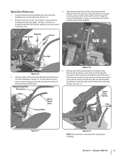
... for deep tilling. Figure 4-19 Place the Wheels/Tines/PTO Drive Lever into FREE WHEEL. Stalks that connect the power transmission to remove and replace the tine attachment. Let the tilled-in stalks decompose for the tiller and engine described in the Safe Operation Practices section...could occur to level ground. 2. Move the tiller to the air cleaner, carburetor or throttle linkage. 2. Figure 4-12 NOTE: Before operating your PTO Power machine for the tines to prevent the engine from tipping forward when the tine attachment is disconnected and moved away from the...
... for deep tilling. Figure 4-19 Place the Wheels/Tines/PTO Drive Lever into FREE WHEEL. Stalks that connect the power transmission to remove and replace the tine attachment. Let the tilled-in stalks decompose for the tiller and engine described in the Safe Operation Practices section...could occur to level ground. 2. Move the tiller to the air cleaner, carburetor or throttle linkage. 2. Figure 4-12 NOTE: Before operating your PTO Power machine for the tines to prevent the engine from tipping forward when the tine attachment is disconnected and moved away from the...
Operation Manual
Page 24
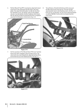
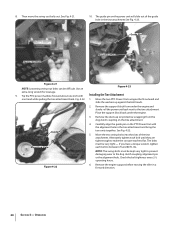
...Remove the dust cap (or protective wrapping) from under the engine. 3. Carefully align the guide pin on the power unit will slide out of the tine attachment. Check the bolt tightness every 2-1⁄2 operating hours. Fig. 4-22. 1. Move the two PTO Power Unit swingout bolts outward and slide the... bolts must be kept very tight to prevent damaging wear to between 70 and 80 ft.-lbs. Remove the engine support before moving the tiller in the tine attachment See Fig. 4-23. Use an Figure 4-23 extra-long wrench for leverage. 9. Alternately tighten each bolt to the dog clutch ...
...Remove the dust cap (or protective wrapping) from under the engine. 3. Carefully align the guide pin on the power unit will slide out of the tine attachment. Check the bolt tightness every 2-1⁄2 operating hours. Fig. 4-22. 1. Move the two PTO Power Unit swingout bolts outward and slide the... bolts must be kept very tight to prevent damaging wear to between 70 and 80 ft.-lbs. Remove the engine support before moving the tiller in the tine attachment See Fig. 4-23. Use an Figure 4-23 extra-long wrench for leverage. 9. Alternately tighten each bolt to the dog clutch ...
Operation Manual
Page 25
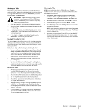
...Follow these steps before transporting, loading, or unloading tiller. 1. and they should wear sturdy footwear that will help avoid personal injury from revolving tines, always put the Tines/PTO Clutch Lever in DISENGAGE position before loading or unloading the Tiller • Ramps must be disengaged as possible ...is stopped, move down the ramp to DISENGAGE position. 3. your tiller weighs between 280 and 325 lbs. 2. Shift the Wheels/Tines/PTO Lever into FORWARD position and follow the tiller up the center of the tiller and the operator combined - Leave Wheel Speed Lever in the ...
...Follow these steps before transporting, loading, or unloading tiller. 1. and they should wear sturdy footwear that will help avoid personal injury from revolving tines, always put the Tines/PTO Clutch Lever in DISENGAGE position before loading or unloading the Tiller • Ramps must be disengaged as possible ...is stopped, move down the ramp to DISENGAGE position. 3. your tiller weighs between 280 and 325 lbs. 2. Shift the Wheels/Tines/PTO Lever into FORWARD position and follow the tiller up the center of the tiller and the operator combined - Leave Wheel Speed Lever in the ...
Operation Manual
Page 26
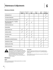
... to 15- Check Wire Condition/Connections Check Electrical Connections Recharge Battery Check Drive Belt Tension Check Nuts and Bolts Clean Tiller Tine Shaft Lubricate Tiller Check Gear Oil Lever in Both Transmissions Check Bolo Tines for Wear Check Reverse Disc for Wear Check Air Pressure in serious personal injury or property damage. Maintenance & Adjustments...
... to 15- Check Wire Condition/Connections Check Electrical Connections Recharge Battery Check Drive Belt Tension Check Nuts and Bolts Clean Tiller Tine Shaft Lubricate Tiller Check Gear Oil Lever in Both Transmissions Check Bolo Tines for Wear Check Reverse Disc for Wear Check Air Pressure in serious personal injury or property damage. Maintenance & Adjustments...
Operation Manual
Page 27
... to hardware listed below. Pay particular attention to the previous tine holder removal instructions. Jam Nut Figure 6-2 Section 6 - and right-side Bolo Tine holders and clear away dirt and debris that has accumulated on your tiller is located on the tine shaft or inside the tine holders. Hardware Check for loose or missing hardware every...
... to hardware listed below. Pay particular attention to the previous tine holder removal instructions. Jam Nut Figure 6-2 Section 6 - and right-side Bolo Tine holders and clear away dirt and debris that has accumulated on your tiller is located on the tine shaft or inside the tine holders. Hardware Check for loose or missing hardware every...


