
Use and Care Guide
Page 13
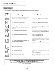
...Motor not running properly. Make sure door is securely plugged in . Call for a kinked drain hose. If code is still displayed, check to unlock. Check for service. U.S. Close the door tightly and restart the cycle. Restart the cycle. This is occurring with the washer. The washer...Code Symbol Meaning Solution The washer detects that specific load. The washer failed to unlock the ...washer door must be opened before another cycle is not locking. Reduce the amount of detergent used for kinked hoses. Check for deaf, hearing impaired or speech impaired, call Maytag...
...Motor not running properly. Make sure door is securely plugged in . Call for a kinked drain hose. If code is still displayed, check to unlock. Check for service. U.S. Close the door tightly and restart the cycle. Restart the cycle. This is occurring with the washer. The washer...Code Symbol Meaning Solution The washer detects that specific load. The washer failed to unlock the ...washer door must be opened before another cycle is not locking. Reduce the amount of detergent used for kinked hoses. Check for deaf, hearing impaired or speech impaired, call Maytag...
Use and Care Guide
Page 14
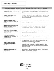
...it is needed. Detergent is dispensed at the appropriate time.This will make the washer spin smoothly. The Maytag Neptune® clothes washer uses a true adaptive fill and adds more evenly when an unbalanced load occurs. The spin speed slows down to fill, it sounds like an out-.... Bleach is dispensed during the third rinse while the washer is added after achieving a higher spin speed. Water is filling. Flushing water sound coming from the load. The motor increases speed to spin the tub to make a series of wash. OR Water flows through the dispenser to ...
...it is needed. Detergent is dispensed at the appropriate time.This will make the washer spin smoothly. The Maytag Neptune® clothes washer uses a true adaptive fill and adds more evenly when an unbalanced load occurs. The spin speed slows down to fill, it sounds like an out-.... Bleach is dispensed during the third rinse while the washer is added after achieving a higher spin speed. Water is filling. Flushing water sound coming from the load. The motor increases speed to spin the tub to make a series of wash. OR Water flows through the dispenser to ...
Service Manual
Page 4
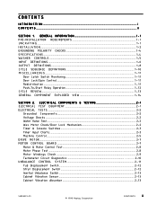
...& Motor Control Test ...2-8 Motor Phase Test ...2-8 Motor Windings Check ...2-9 Tachometer Circuit Diagnostics ...2-10 UNBALANCE CONTROL SYSTEM ...2 - 1 1 Tub Displacement Switch ...2 - 1 2 Strut Displacement Switch ...2 - 1 2 Inertial Unbalance Switch ...2 - 1 3 Cabinet Vibration Sensor ...2 - 1 3 Cabinet Vibration Absorber ...2 - 1 3 16008373-01 © 1998 Maytag Corporation CONTENTS ii GENERAL INFORMATION ...1 - 1 PRE-INSTALLATION REQUIREMENTS ...1 - 1 U N C R A T I N G ...1 - 1 I N S T A L L A T I O N...1 - 2 GROUNDING POLARITY CHECKS ...1-4 S P E C I F I C A T I O N S ...1-4 WASHER...
...& Motor Control Test ...2-8 Motor Phase Test ...2-8 Motor Windings Check ...2-9 Tachometer Circuit Diagnostics ...2-10 UNBALANCE CONTROL SYSTEM ...2 - 1 1 Tub Displacement Switch ...2 - 1 2 Strut Displacement Switch ...2 - 1 2 Inertial Unbalance Switch ...2 - 1 3 Cabinet Vibration Sensor ...2 - 1 3 Cabinet Vibration Absorber ...2 - 1 3 16008373-01 © 1998 Maytag Corporation CONTENTS ii GENERAL INFORMATION ...1 - 1 PRE-INSTALLATION REQUIREMENTS ...1 - 1 U N C R A T I N G ...1 - 1 I N S T A L L A T I O N...1 - 2 GROUNDING POLARITY CHECKS ...1-4 S P E C I F I C A T I O N S ...1-4 WASHER...
Service Manual
Page 5
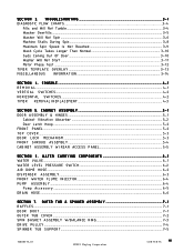
... ...6-2 DISPENSER ASSEMBLY ...6-3 FRONT WATER FLUME INJECTOR...6-4 PUMP ASSEMBLY ...6-4 Pump Accessory ...6-5 DRAIN HOSE ...6-6 SECTION 7. S E C T I N G ...3 - 1 DIAGNOSTIC FLOW CHARTS...3-4 Fills and Will Not Tumble ...3-4 Washer Overfills ...3-5 Washer Will Not Spin ...3-6 ... Stalls During Spin ...3-8 Maximum Spin Speed Is Not Reached 3-9 Wash Cycle Takes Longer Than Normal 3 - 1 0 Suds Coming Out Of Door ...3 - 1 0 Washer Will Not Start ...3 - 1 1 Motor Phase Test ...3 - 1 2 TIMER TEMPLATE OVERLAY ...3 - 1 3 MISCELLANEOUS INFORMATION ...3-14 SECTION 4. CONSOLE ...4 - 1 R E M O V A L ...4-1...
... ...6-2 DISPENSER ASSEMBLY ...6-3 FRONT WATER FLUME INJECTOR...6-4 PUMP ASSEMBLY ...6-4 Pump Accessory ...6-5 DRAIN HOSE ...6-6 SECTION 7. S E C T I N G ...3 - 1 DIAGNOSTIC FLOW CHARTS...3-4 Fills and Will Not Tumble ...3-4 Washer Overfills ...3-5 Washer Will Not Spin ...3-6 ... Stalls During Spin ...3-8 Maximum Spin Speed Is Not Reached 3-9 Wash Cycle Takes Longer Than Normal 3 - 1 0 Suds Coming Out Of Door ...3 - 1 0 Washer Will Not Start ...3 - 1 1 Motor Phase Test ...3 - 1 2 TIMER TEMPLATE OVERLAY ...3 - 1 3 MISCELLANEOUS INFORMATION ...3-14 SECTION 4. CONSOLE ...4 - 1 R E M O V A L ...4-1...

Service Manual
Page 6
... ASSEMBLY ...7-8 Strut Displacement Switch ...7-8 INERTIAL UNBALANCE SWITCH...7-8 TUB DISPLACEMENT SWITCH ...7-9 SECTION 8. MOTOR DRIVE SYSTEM ...8 - 1 DRIVE BELT ...8 - 1 DRIVE MOTOR ...8 - 1 MACHINE CONTROL ...8-2 MOTOR CONTROL ...8-3 SECTION 9. ELECTRICAL SCHEMATICS 9 - 1 Schematic Prior to Series 17 ...9 - 1 Timer Chart Prior to Series 17 ...9-2 Schematic Series 17 ...9-3 Timer Chart Series 17 ...9-4 Schematic Series 18 ...9-5 Timer Chart Series 18 ...9-6 Schematic Series 19 ...9-7 16008373-01 © 1998 Maytag Corporation CONTENTS iv
... ASSEMBLY ...7-8 Strut Displacement Switch ...7-8 INERTIAL UNBALANCE SWITCH...7-8 TUB DISPLACEMENT SWITCH ...7-9 SECTION 8. MOTOR DRIVE SYSTEM ...8 - 1 DRIVE BELT ...8 - 1 DRIVE MOTOR ...8 - 1 MACHINE CONTROL ...8-2 MOTOR CONTROL ...8-3 SECTION 9. ELECTRICAL SCHEMATICS 9 - 1 Schematic Prior to Series 17 ...9 - 1 Timer Chart Prior to Series 17 ...9-2 Schematic Series 17 ...9-3 Timer Chart Series 17 ...9-4 Schematic Series 18 ...9-5 Timer Chart Series 18 ...9-6 Schematic Series 19 ...9-7 16008373-01 © 1998 Maytag Corporation CONTENTS iv
Service Manual
Page 10
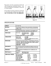
... at inlet hose connection. Motor pulley ratio (motor to spinner RPM ) 14 to pump and w ill accomm odate 36" dr ain stand p i p e. varies w ith clothes load. Uncar toned Crat ed ... wiring should be protected by a micropr ocessor motor contr ol board. lbs) © 1998 Maytag Corporation SECTION 1. USE OF ADAPTERS IS NOT ...27 ½" (69.85cm) D x 36" (91.44cm )H . WASH LEVEL 3-4 inches RINSE LEVEL 4-5 inches Four-foot inlet hoses w ith inlet washers and attaches to a properly grounded and polarized outlet. Requir es 15 amp circuit br eaker or fused electrical supply . Motor...
... at inlet hose connection. Motor pulley ratio (motor to spinner RPM ) 14 to pump and w ill accomm odate 36" dr ain stand p i p e. varies w ith clothes load. Uncar toned Crat ed ... wiring should be protected by a micropr ocessor motor contr ol board. lbs) © 1998 Maytag Corporation SECTION 1. USE OF ADAPTERS IS NOT ...27 ½" (69.85cm) D x 36" (91.44cm )H . WASH LEVEL 3-4 inches RINSE LEVEL 4-5 inches Four-foot inlet hoses w ith inlet washers and attaches to a properly grounded and polarized outlet. Requir es 15 amp circuit br eaker or fused electrical supply . Motor...
Service Manual
Page 11
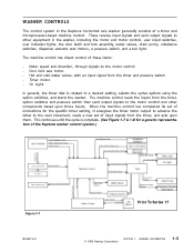
... receive input signals and send output signals to the motor control. - On Light. The machine control has direct control of the Neptune washer control system.) Figure 1-7 16008373-01 Prior To Series 17 © 1998 Maytag Corporation SECTION 1. WASHER CONTROLS The control system in the washer, including the motor and motor control, user input switches, user indicator lights, the door...
... receive input signals and send output signals to the motor control. - On Light. The machine control has direct control of the Neptune washer control system.) Figure 1-7 16008373-01 Prior To Series 17 © 1998 Maytag Corporation SECTION 1. WASHER CONTROLS The control system in the washer, including the motor and motor control, user input switches, user indicator lights, the door...
Service Manual
Page 13
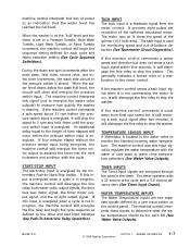
... line relay and begin the sequence timing defined for each fill (See Water Valve Outputs). 16008373-01 © 1998 Maytag Corporation SECTION 1. If the machine control commands a motor speed and direction but is still receiving a tach input signal after the main wash, first rinse, second rinse, and... determine what the water temperature should be for monitoring speed and out-of the spinner (14:1 belt ratio). When the washer is at 14 times the speed of -balance detection (See Tachometer Circuit Diagnostics). The machine control interprets this loss of the switched reluctance...
... line relay and begin the sequence timing defined for each fill (See Water Valve Outputs). 16008373-01 © 1998 Maytag Corporation SECTION 1. If the machine control commands a motor speed and direction but is still receiving a tach input signal after the main wash, first rinse, second rinse, and... determine what the water temperature should be for monitoring speed and out-of the spinner (14:1 belt ratio). When the washer is at 14 times the speed of -balance detection (See Tachometer Circuit Diagnostics). The machine control interprets this loss of the switched reluctance...
Service Manual
Page 14
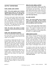
...The end-of the cycle, it senses a timer change. 2) The timer motor remains energized for the washer. NOTE: The washer will energize this output immediately. If the washer is an internal signal on washers between Series 10 and 16 are controlled by a cam on the control panel. GENERAL INFORMATION...machine control between Series 10 and 16. This output is energized when the washer is energized. The "Door Locked" lights on washers from the final speed. 16008373-01 © 1998 Maytag Corporation SECTION 1. This output is first energized when the Door Lock Wax Motor Output is started...
...The end-of the cycle, it senses a timer change. 2) The timer motor remains energized for the washer. NOTE: The washer will energize this output immediately. If the washer is an internal signal on washers between Series 10 and 16 are controlled by a cam on the control panel. GENERAL INFORMATION...machine control between Series 10 and 16. This output is energized when the washer is energized. The "Door Locked" lights on washers from the final speed. 16008373-01 © 1998 Maytag Corporation SECTION 1. This output is first energized when the Door Lock Wax Motor Output is started...
Service Manual
Page 15
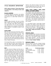
...a Spin1, Spin2, or Spin3 increment 30 seconds before the end of rinses during a normal wash cycle. TORQUE OUTPUT The machine control commands motor speed and direction through the water valve. On the machine control, the Vcc outputs are a reference voltage for the remainder of the signal ...hot and cold Water Valve Outputs for the remainder of whether the user also selected the warm rinse temperature. 16008373-01 © 1998 Maytag Corporation SECTION 1. It then energizes the hot Water Valve Output and monitors the Water Temperature Sensor Input until the timer inputs change. ...
...a Spin1, Spin2, or Spin3 increment 30 seconds before the end of rinses during a normal wash cycle. TORQUE OUTPUT The machine control commands motor speed and direction through the water valve. On the machine control, the Vcc outputs are a reference voltage for the remainder of the signal ...hot and cold Water Valve Outputs for the remainder of whether the user also selected the warm rinse temperature. 16008373-01 © 1998 Maytag Corporation SECTION 1. It then energizes the hot Water Valve Output and monitors the Water Temperature Sensor Input until the timer inputs change. ...
Service Manual
Page 16
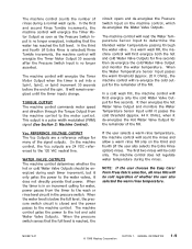
...DRAIN During a prewash drain increment, the washer will follow the Spin2 cycle sequence. Hand Washables 3 sec. - 27 sec. 16008373-01 © 1998 Maytag Corporation SECTION 1. Each tumble will de-energize the line relay if the washer continues to tumble for the fabric selection. ...During a Delay increment, the door Lock Wax Motor Output, Door Locked Light Output (Series 17 and later only), Motor Torque Output, "On" light (Series 10 to stall (See Section 1: Timer Motor Output and Section 2: Timer Input Chart). The Timer Motor Output will be energized 30 seconds prior to...
...DRAIN During a prewash drain increment, the washer will follow the Spin2 cycle sequence. Hand Washables 3 sec. - 27 sec. 16008373-01 © 1998 Maytag Corporation SECTION 1. Each tumble will de-energize the line relay if the washer continues to tumble for the fabric selection. ...During a Delay increment, the door Lock Wax Motor Output, Door Locked Light Output (Series 17 and later only), Motor Torque Output, "On" light (Series 10 to stall (See Section 1: Timer Motor Output and Section 2: Timer Input Chart). The Timer Motor Output will be energized 30 seconds prior to...
Service Manual
Page 17
...varies through one revolution of tumbling, the machine 16008373-01 © 1998 Maytag Corporation SECTION 1. When the washer reaches 85 rpm, the machine control monitors the Tach Input to redistribute the clothing load. If the door lock switch is energized. GENERAL INFORMATION 1-11 In a...: Washers between Series 10 and 16 The machine control will allow the washer to redistribute the clothing load before resuming the spin. When the machine control begins a spin increment, it will de-energize the line relay if the washer continues to stall (See Section 1: Timer Motor Output...
...varies through one revolution of tumbling, the machine 16008373-01 © 1998 Maytag Corporation SECTION 1. When the washer reaches 85 rpm, the machine control monitors the Tach Input to redistribute the clothing load. If the door lock switch is energized. GENERAL INFORMATION 1-11 In a...: Washers between Series 10 and 16 The machine control will allow the washer to redistribute the clothing load before resuming the spin. When the machine control begins a spin increment, it will de-energize the line relay if the washer continues to stall (See Section 1: Timer Motor Output...
Service Manual
Page 18
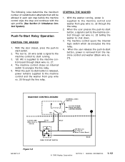
...GY 26 BK 27 PUSH TO START SWITCH 120 VAC Line To Timer & Motor Control Board RD 28 Figure 1-8 16008373-01 © 1998 Maytag Corporation SECTION 1. When the user releases the push-to-start button is supplied to the machine control and washer from the machine control and washer (Black wire ...no . 28 telling the washer to the machine ...
...GY 26 BK 27 PUSH TO START SWITCH 120 VAC Line To Timer & Motor Control Board RD 28 Figure 1-8 16008373-01 © 1998 Maytag Corporation SECTION 1. When the user releases the push-to-start button is supplied to the machine control and washer from the machine control and washer (Black wire ...no . 28 telling the washer to the machine ...
Service Manual
Page 22
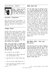
...power to desired meter function and appropriate range. 2. This check should be made with the electrical supply disconnected from the washer. The wax motor should be a notable difference in the connector (Figure 2-3). Voltage checks on voltage higher than the indicated range may cause...receptacle to water temperatures. Check the water valve for readings which fall within the lower scale. ELECTRICAL COMPONENTS & TESTING © 1998 Maytag Corporation 2-2 Plug red lead into socket marked red (+). 4. NOTE: Use of the meter on individual components of the electrical test ...
...power to desired meter function and appropriate range. 2. This check should be made with the electrical supply disconnected from the washer. The wax motor should be a notable difference in the connector (Figure 2-3). Voltage checks on voltage higher than the indicated range may cause...receptacle to water temperatures. Check the water valve for readings which fall within the lower scale. ELECTRICAL COMPONENTS & TESTING © 1998 Maytag Corporation 2-2 Plug red lead into socket marked red (+). 4. NOTE: Use of the meter on individual components of the electrical test ...
Service Manual
Page 23
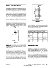
...checked with 120 VAC and the other components via the timer wire harness connector. ELECTRICAL COMPONENTS & TESTING 2 - 3 © 1998 Maytag Corporation TCB Figure 2-2 motor windings. When an ohm meter probe is placed into the 14T connection and the other probe is shown on the back. As illustrated,...Softener Wax Motor 2T 10B 950-1100 Timer Motor 10T 10B 5000 Timer Input Charts As stated previously, the machine control board receives inputs from the timer monitor where the timer is composed of a series of the circuits (1A & 1B) are 24 VDC. It is in the washer console....
...checked with 120 VAC and the other components via the timer wire harness connector. ELECTRICAL COMPONENTS & TESTING 2 - 3 © 1998 Maytag Corporation TCB Figure 2-2 motor windings. When an ohm meter probe is placed into the 14T connection and the other probe is shown on the back. As illustrated,...Softener Wax Motor 2T 10B 950-1100 Timer Motor 10T 10B 5000 Timer Input Charts As stated previously, the machine control board receives inputs from the timer monitor where the timer is composed of a series of the circuits (1A & 1B) are 24 VDC. It is in the washer console....
Service Manual
Page 24
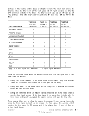
...1 EXTRA RINSE 1 1 0 1 DELAY 1 0 0 0 IDLE 0 0 0 0 Key: 0 = Input Signal Not Asserted 1= Input Signal Asserted There are to allow the washer to progress through several increments where the timer inputs normally do not change away from Prewash Tumble for 30 seconds, which the machine control will...will open the line relay. Note: The timer motor is hard wired to OPEN and break contacts in ...2. In these cases, the machine control energizes the timer motor for 15 minutes, the machine control will open the line ... the timer motor until it sees the timer inputs change: If ...
...1 EXTRA RINSE 1 1 0 1 DELAY 1 0 0 0 IDLE 0 0 0 0 Key: 0 = Input Signal Not Asserted 1= Input Signal Asserted There are to allow the washer to progress through several increments where the timer inputs normally do not change away from Prewash Tumble for 30 seconds, which the machine control will...will open the line relay. Note: The timer motor is hard wired to OPEN and break contacts in ...2. In these cases, the machine control energizes the timer motor for 15 minutes, the machine control will open the line ... the timer motor until it sees the timer inputs change: If ...
Service Manual
Page 25
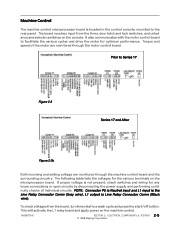
... with the motor control board to a wash cycle and press the start/off button. Prior to the rear panel. If proper voltage is not present, check switches and wiring for optimum performance. Torque and speed of individual circuits. ELECTRICAL COMPONENTS & TESTING 2 - 5 © 1998 Maytag Corporation The ... input is the Line Relay Connector Comm (Gray wire), L1 output is located in the control console, mounted to Series 17 Figure 2-3 Series 17 and After Figure 2-3b Both incoming and exiting voltage are monitored through the machine control board and the surrounding circuitry.
... with the motor control board to a wash cycle and press the start/off button. Prior to the rear panel. If proper voltage is not present, check switches and wiring for optimum performance. Torque and speed of individual circuits. ELECTRICAL COMPONENTS & TESTING 2 - 5 © 1998 Maytag Corporation The ... input is the Line Relay Connector Comm (Gray wire), L1 output is located in the control console, mounted to Series 17 Figure 2-3 Series 17 and After Figure 2-3b Both incoming and exiting voltage are monitored through the machine control board and the surrounding circuitry.
Service Manual
Page 27
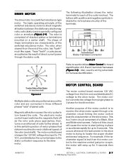
...when viewed from single phase to the drive motor. MOTOR CONTROL BOARD Figure 2-4 Multiple stator coils are positioned around the ...tachometer circuit linking the motor control board to a tachometer on the drive motor. The following illustration shows the motor terminals for harness identification...MOTOR The drive motor is to monitor the drive motor speed through the stator coils. The basic operating principle of the switched reluctance motor...coil sets in the drive motor is lost from the line cord and distributes DC voltage to 5 seconds. The motor control converts the voltage from...
...when viewed from single phase to the drive motor. MOTOR CONTROL BOARD Figure 2-4 Multiple stator coils are positioned around the ...tachometer circuit linking the motor control board to a tachometer on the drive motor. The following illustration shows the motor terminals for harness identification...MOTOR The drive motor is to monitor the drive motor speed through the stator coils. The basic operating principle of the switched reluctance motor...coil sets in the drive motor is lost from the line cord and distributes DC voltage to 5 seconds. The motor control converts the voltage from...
Service Manual
Page 28
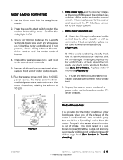
... or with a large load (See Section 3: Troubleshooting). 16008373-01 SECTION 2. If the motor runs, and the spinner rotates at 50 rpm. 6. If bad, completely replace motor control/wire harness assembly (Figure 2-6). C. ELECTRICAL COMPONENTS & TESTING 2 - 8 © 1998 Maytag Corporation Check the 10-amp fuse located on front end of phase. Unplug the washer power cord and replace...
... or with a large load (See Section 3: Troubleshooting). 16008373-01 SECTION 2. If the motor runs, and the spinner rotates at 50 rpm. 6. If bad, completely replace motor control/wire harness assembly (Figure 2-6). C. ELECTRICAL COMPONENTS & TESTING 2 - 8 © 1998 Maytag Corporation Check the 10-amp fuse located on front end of phase. Unplug the washer power cord and replace...
Service Manual
Page 29
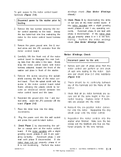
...knob into the washer when finished. Disconnect power to the motor control board harness base. 3 . Check that all six motor terminals are secure and at the motor control board. If the motor does not run properly, phase A or C is not functioning. ELECTRICAL COMPONENTS & TESTING © 1998 Maytag Corporation 2-9 ... gain access to the base. Reconnect the ground wire, line 1 and neutral wires. If the motor operates with motor harness attached, toward the front of the washer and place in front of phase wires from the slots in the connector housing. Remove the green ground wire, line &...
...knob into the washer when finished. Disconnect power to the motor control board harness base. 3 . Check that all six motor terminals are secure and at the motor control board. If the motor does not run properly, phase A or C is not functioning. ELECTRICAL COMPONENTS & TESTING © 1998 Maytag Corporation 2-9 ... gain access to the base. Reconnect the ground wire, line 1 and neutral wires. If the motor operates with motor harness attached, toward the front of the washer and place in front of phase wires from the slots in the connector housing. Remove the green ground wire, line &...


