
Use and Care Guide
Page 9
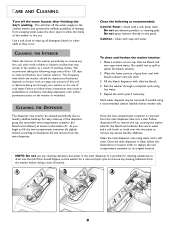
... clean-up of the dispenser, grasp the removable two-compartment container (for cleaning substances to drain into the tub. Clean the main dispenser area using a recommended cleaner labeled clothes washer safe. If this should be cleaned periodically due to laundry additive build-up all detergent, bleach...supply to the clothes washer and prevent the unlikely possibility of damage from the main dispenser. Use a soft cloth to wipe up . CLEANING THE DISPENSER To clean and freshen the washer interior: 1. Once the main dispenser is removed from the washer before doing a load of one cup ...
... clean-up of the dispenser, grasp the removable two-compartment container (for cleaning substances to drain into the tub. Clean the main dispenser area using a recommended cleaner labeled clothes washer safe. If this should be cleaned periodically due to laundry additive build-up all detergent, bleach...supply to the clothes washer and prevent the unlikely possibility of damage from the main dispenser. Use a soft cloth to wipe up . CLEANING THE DISPENSER To clean and freshen the washer interior: 1. Once the main dispenser is removed from the washer before doing a load of one cup ...
Use and Care Guide
Page 11
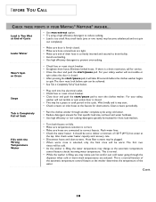
...capacity and recovery rate. • Disconnect hoses and clean screens. BEFORE YOU CALL CHECK THESE POINTS IF YOUR MAYTAG® NEPTUNE® WASHER... For your safety, washer will be warm. Flush water lines. • Check the water heater. It should be achieved. •...drain hose is Completely Full of Cycle • Use max extract option. • Try using cold water. • Reduce detergent amount for that specific load size, soil level and water hardness. • Use high efficiency or low sudsing detergent specially formulated for front load washers. For your safety, washer...
...capacity and recovery rate. • Disconnect hoses and clean screens. BEFORE YOU CALL CHECK THESE POINTS IF YOUR MAYTAG® NEPTUNE® WASHER... For your safety, washer will be warm. Flush water lines. • Check the water heater. It should be achieved. •...drain hose is Completely Full of Cycle • Use max extract option. • Try using cold water. • Reduce detergent amount for that specific load size, soil level and water hardness. • Use high efficiency or low sudsing detergent specially formulated for front load washers. For your safety, washer...
Use and Care Guide
Page 13
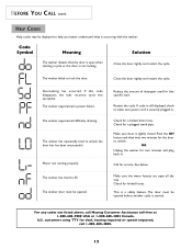
... Meaning Solution The washer detects that specific load. If this code disappears, the suds recovery cycle was successful. The washer door must be opened . Reduce the amount of detergent used for deaf, hearing impaired or speech impaired, call Maytag Customer Assistance toll-... been unsuccessful. Oversudsing has occurred. The washer experienced difficulty draining. OR Unplug the washer for the door to fill. Check for a kinked drain hose. The washer has repeatedly tried to lock the door. See below. The washer has tried to unlock. This is securely...
... Meaning Solution The washer detects that specific load. If this code disappears, the suds recovery cycle was successful. The washer door must be opened . Reduce the amount of detergent used for deaf, hearing impaired or speech impaired, call Maytag Customer Assistance toll-... been unsuccessful. Oversudsing has occurred. The washer experienced difficulty draining. OR Unplug the washer for the door to fill. Check for a kinked drain hose. The washer has repeatedly tried to lock the door. See below. The washer has tried to unlock. This is securely...
Use and Care Guide
Page 14
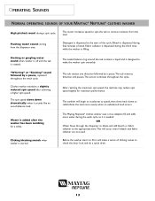
...load occurs. The motor increases speed to spin the tub to remove moisture from the dispenser area. Fabric softener is dispensed during the wash cycle as it will make the washer spin smoothly. The spin speed slows down to make a series of wash. Clicking/draining sounds when washer ... OPERATING SOUNDS OF YOUR MAYTAG® NEPTUNE® CLOTHES WASHER High pitched sound during final minutes of clicking noises to check the door lock and do a quick drain. 13 Detergent is designed to redistribute the load more water during the third rinse while the washer is started. The sealed...
...load occurs. The motor increases speed to spin the tub to remove moisture from the dispenser area. Fabric softener is dispensed during the wash cycle as it will make the washer spin smoothly. The spin speed slows down to make a series of wash. Clicking/draining sounds when washer ... OPERATING SOUNDS OF YOUR MAYTAG® NEPTUNE® CLOTHES WASHER High pitched sound during final minutes of clicking noises to check the door lock and do a quick drain. 13 Detergent is designed to redistribute the load more water during the third rinse while the washer is started. The sealed...
Service Manual
Page 5
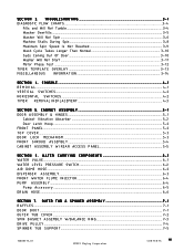
... 6 - 1 WATER VALVE...6 - 1 WATER LEVEL PRESSURE SWITCH...6-2 AIR DOME HOSE ...6-2 DISPENSER ASSEMBLY ...6-3 FRONT WATER FLUME INJECTOR...6-4 PUMP ASSEMBLY ...6-4 Pump Accessory ...6-5 DRAIN HOSE ...6-6 SECTION 7. CONSOLE ...4 - 1 R E M O V A L ...4-1 VERTICAL SWITCHES...4-2 HORIZONTAL SWITCHES ...4-2 TIMER REMOVAL/REPLACEMENT...4-3 SECTION 5. S E C T I N G ...3 - 1 DIAGNOSTIC FLOW CHARTS...3-4 Fills and Will Not Tumble ...3-4 Washer Overfills ...3-5 Washer Will Not Spin ...3-6 Machine Stalls During Spin ...3-8 Maximum Spin Speed Is Not...
... 6 - 1 WATER VALVE...6 - 1 WATER LEVEL PRESSURE SWITCH...6-2 AIR DOME HOSE ...6-2 DISPENSER ASSEMBLY ...6-3 FRONT WATER FLUME INJECTOR...6-4 PUMP ASSEMBLY ...6-4 Pump Accessory ...6-5 DRAIN HOSE ...6-6 SECTION 7. CONSOLE ...4 - 1 R E M O V A L ...4-1 VERTICAL SWITCHES...4-2 HORIZONTAL SWITCHES ...4-2 TIMER REMOVAL/REPLACEMENT...4-3 SECTION 5. S E C T I N G ...3 - 1 DIAGNOSTIC FLOW CHARTS...3-4 Fills and Will Not Tumble ...3-4 Washer Overfills ...3-5 Washer Will Not Spin ...3-6 Machine Stalls During Spin ...3-8 Maximum Spin Speed Is Not...
Service Manual
Page 7
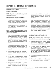
...INSTRUCTIONS NOTE: The following steps must accept 1½" O.D. Remove the accessory package from unbalanced load situations. This can cause damage to a minimum height of 36" is recommended. Never install washer on a solid floor. may need to be elevated to the pump, hoses and other... components. Wood floor constructions may 16008373-01 © 1998 Maytag Corporation SECTION 1. A 36" high standpipe is obtained with a siphon break, and the drain hose must be...
...INSTRUCTIONS NOTE: The following steps must accept 1½" O.D. Remove the accessory package from unbalanced load situations. This can cause damage to a minimum height of 36" is recommended. Never install washer on a solid floor. may need to be elevated to the pump, hoses and other... components. Wood floor constructions may 16008373-01 © 1998 Maytag Corporation SECTION 1. A 36" high standpipe is obtained with a siphon break, and the drain hose must be...
Service Manual
Page 9
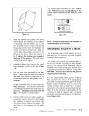
...the plastic hook of the strap. 7. Install the rubber feet, found in the installation package, on all Maytag products operating on the back of the washer and snap into drain standpipe. The power cord should be properly grounded and polarized. Note the H and C designations on the...person installing the appliance to the floor. Install gooseneck end of the washer. Figure 1-4 Figure 1-5 4. When the washer is not airtight between the drain hose and standpipe. Then route the drain hose through the drain hose strap on 120 Volts AC must be taken into position to ...
...the plastic hook of the strap. 7. Install the rubber feet, found in the installation package, on all Maytag products operating on the back of the washer and snap into drain standpipe. The power cord should be properly grounded and polarized. Note the H and C designations on the...person installing the appliance to the floor. Install gooseneck end of the washer. Figure 1-4 Figure 1-5 4. When the washer is not airtight between the drain hose and standpipe. Then route the drain hose through the drain hose strap on 120 Volts AC must be taken into position to ...
Service Manual
Page 11
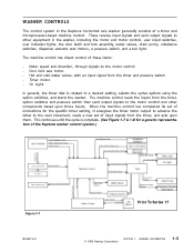
... wax motor. - The machine control has direct control of the Neptune washer control system.) Figure 1-7 16008373-01 Prior To Series 17 © 1998 Maytag Corporation SECTION 1. When the machine control has completed its set of... instructions for a generic representation of these items: - WASHER CONTROLS The control system in the washer, including the motor and motor control, user input switches, user indicator lights, the door latch and lock assembly, water valves, drain...
... wax motor. - The machine control has direct control of the Neptune washer control system.) Figure 1-7 16008373-01 Prior To Series 17 © 1998 Maytag Corporation SECTION 1. When the machine control has completed its set of... instructions for a generic representation of these items: - WASHER CONTROLS The control system in the washer, including the motor and motor control, user input switches, user indicator lights, the door latch and lock assembly, water valves, drain...
Service Manual
Page 13
... control interprets this signal (not to energize the water valve outputs) to measure how quickly the washer is draining. When the washer is at 14 times the speed of the switched reluctance motor. When the water level drains below the wash full level, the circuit will disengage the line relay, both water valve output... down from the motor control. If this input is energized when a cycle is used for each fill (See Water Valve Outputs). 16008373-01 © 1998 Maytag Corporation SECTION 1. The motor runs at the "full" level and the timer is set in the pressure switch is closed.
... control interprets this signal (not to energize the water valve outputs) to measure how quickly the washer is draining. When the washer is at 14 times the speed of the switched reluctance motor. When the water level drains below the wash full level, the circuit will disengage the line relay, both water valve output... down from the motor control. If this input is energized when a cycle is used for each fill (See Water Valve Outputs). 16008373-01 © 1998 Maytag Corporation SECTION 1. The motor runs at the "full" level and the timer is set in the pressure switch is closed.
Service Manual
Page 14
... 2) The timer motor remains energized for 50 seconds after . This delay is in a Prewash Drain, Bleach Dispense, Spin1, Rinse Tumble, Spin2, or Spin3 increment, the machine control will stop the washer by a "Door Locked" light switch. This output remains energized until 30 seconds before energizing the ... wait for three minutes before the washer begins to coast from the final speed. 16008373-01 © 1998 Maytag Corporation SECTION 1. This output is first energized when the Door Lock Wax Motor Output is an internal signal on washers between Series 10 and 16 are controlled by ...
... 2) The timer motor remains energized for 50 seconds after . This delay is in a Prewash Drain, Bleach Dispense, Spin1, Rinse Tumble, Spin2, or Spin3 increment, the machine control will stop the washer by a "Door Locked" light switch. This output remains energized until 30 seconds before energizing the ... wait for three minutes before the washer begins to coast from the final speed. 16008373-01 © 1998 Maytag Corporation SECTION 1. This output is first energized when the Door Lock Wax Motor Output is an internal signal on washers between Series 10 and 16 are controlled by ...
Service Manual
Page 16
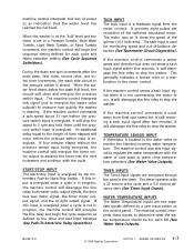
...The machine control will sound if the user had selected the End-of the final spin. PREWASH DRAIN During a prewash drain increment, the washer will continue to the end of -Cycle Signal option. This allows time for information on the ...AY During a Delay increment, the door Lock Wax Motor Output, Door Locked Light Output (Series 17 and later only), Motor Torque Output, "On" light (Series 10 to Section 2: Timer Input Charts for the Door Lock Wax Motor to advance the...Care/Perm Press 6 sec. - 24 sec. Hand Washables 3 sec. - 27 sec. 16008373-01 © 1998 Maytag Corporation SECTION 1.
...The machine control will sound if the user had selected the End-of the final spin. PREWASH DRAIN During a prewash drain increment, the washer will continue to the end of -Cycle Signal option. This allows time for information on the ...AY During a Delay increment, the door Lock Wax Motor Output, Door Locked Light Output (Series 17 and later only), Motor Torque Output, "On" light (Series 10 to Section 2: Timer Input Charts for the Door Lock Wax Motor to advance the...Care/Perm Press 6 sec. - 24 sec. Hand Washables 3 sec. - 27 sec. 16008373-01 © 1998 Maytag Corporation SECTION 1.
Service Manual
Page 19
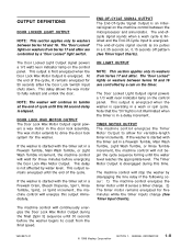
...s 6/ 2 4 Hand W ashab les 3/ 2 7 16008373-01 © 1998 Maytag Corporation SECTION 1. CYCLE REVIEW Main Wash Time/Total Cycle Time - N on water fill times, due to types of clothing loads, available water pressure and the time for the door lock system to reduce the suds present...sy C are approximate and will go into a suds reduction routine, consisting of a series of pause between tumbles. GENERAL INFORMATION 1-13 Number of seconds tumbling/Number of seconds of additional rinse and partial drain cycles to retract at End of suds. The total cycle times are / Perm Press...
...s 6/ 2 4 Hand W ashab les 3/ 2 7 16008373-01 © 1998 Maytag Corporation SECTION 1. CYCLE REVIEW Main Wash Time/Total Cycle Time - N on water fill times, due to types of clothing loads, available water pressure and the time for the door lock system to reduce the suds present...sy C are approximate and will go into a suds reduction routine, consisting of a series of pause between tumbles. GENERAL INFORMATION 1-13 Number of seconds tumbling/Number of seconds of additional rinse and partial drain cycles to retract at End of suds. The total cycle times are / Perm Press...
Service Manual
Page 23
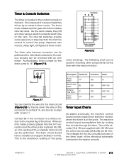
...(1A & 1B) are 24 VDC. Two of the electrical schematic enclosed in the washer console. 16008373-01 SECTION 2. ELECTRICAL COMPONENTS & TESTING 2 - 3 © 1998 Maytag Corporation Contact 8B in the connector is composed of a series of the timer. TCB Figure 2-2 motor windings. It is a direct contact to... leg of switches driven by routing four circuits through the timer. Figure 2-1 You can be pulled and the individual contacts for the drain pump is 14T (Figure 2-1). Timer & Console Switches The timer is in the cycle. The timer motor rotates a pinion gear which...
...(1A & 1B) are 24 VDC. Two of the electrical schematic enclosed in the washer console. 16008373-01 SECTION 2. ELECTRICAL COMPONENTS & TESTING 2 - 3 © 1998 Maytag Corporation Contact 8B in the connector is composed of a series of the timer. TCB Figure 2-2 motor windings. It is a direct contact to... leg of switches driven by routing four circuits through the timer. Figure 2-1 You can be pulled and the individual contacts for the drain pump is 14T (Figure 2-1). Timer & Console Switches The timer is in the cycle. The timer motor rotates a pinion gear which...
Service Manual
Page 24
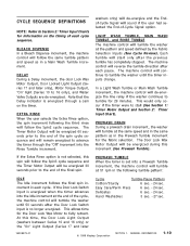
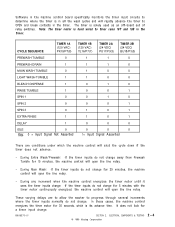
... TESTING 2 - 4 © 1998 Maytag Corporation CYCLE SEQUENCE TIMER 1A (120 VAC...ER 1B (120 VAC) YL16/P7(7) TIMER 2A (24 VDC) PU17/P3(3) TIM ER 2B (24 VDC) BU18/P3(5) PREWASH TUM BLE 0 1 1 0 PREWASH DRAIN 1 1 1 0 MAIN WASH TUM BLE 0 1 0 0 LIGHT WA SH TUM BLE 1 1 0 0 BLEACH DISPENSE 1 0 1 0 RINSE TUMBLE 1 0...0 0 0 IDLE 0 0 0 0 Key: 0 = Input Signal Not Asserted 1= Input Signal Asserted There are to allow the washer to progress through several increments where the timer inputs normally do not change . 16008373-01 SECTION 2. Note: The timer motor is hard...
... TESTING 2 - 4 © 1998 Maytag Corporation CYCLE SEQUENCE TIMER 1A (120 VAC...ER 1B (120 VAC) YL16/P7(7) TIMER 2A (24 VDC) PU17/P3(3) TIM ER 2B (24 VDC) BU18/P3(5) PREWASH TUM BLE 0 1 1 0 PREWASH DRAIN 1 1 1 0 MAIN WASH TUM BLE 0 1 0 0 LIGHT WA SH TUM BLE 1 1 0 0 BLEACH DISPENSE 1 0 1 0 RINSE TUMBLE 1 0...0 0 0 IDLE 0 0 0 0 Key: 0 = Input Signal Not Asserted 1= Input Signal Asserted There are to allow the washer to progress through several increments where the timer inputs normally do not change . 16008373-01 SECTION 2. Note: The timer motor is hard...
Service Manual
Page 36
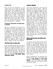
.... 16008373-01 © 1998 Maytag Corporation SECTION 3. Check the tightness of the upper and lower weights on side of the timer input wires leading from the washer. Place hand on the outer... cabinet flex. Also, check wiring of all console switches to start different operations, such as drain, fill, tumble and spin. This ensures the door is fully locked and the switch can ... the cabinet. Check the levelness of the normally-closed switches is activated during an unbalanced load condition. ContinuesTo Tumble After The Wash Cycle Is Finished: Check for continuity at the strut...
.... 16008373-01 © 1998 Maytag Corporation SECTION 3. Check the tightness of the upper and lower weights on side of the timer input wires leading from the washer. Place hand on the outer... cabinet flex. Also, check wiring of all console switches to start different operations, such as drain, fill, tumble and spin. This ensures the door is fully locked and the switch can ... the cabinet. Check the levelness of the normally-closed switches is activated during an unbalanced load condition. ContinuesTo Tumble After The Wash Cycle Is Finished: Check for continuity at the strut...
Service Manual
Page 48
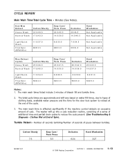
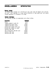
... maximum of 5.0 amps. TROUBLESHOOTING 3 - 1 4 Peak amperage is 7.5 amps during acceleration to 0.10 Kwh per cycle, when using the Regular cycle with water Draining (No tumble) no water Spinning (100 rpm) Spin Acceleration (100-200 rpm) Spinning (400 rpm) Spinning (850 rpm) Wattages: 10-15 50-70 110-...120 140-150 45-50 30-35 85-90 130-150 160-170 400-410 16008373-01 © 1998 Maytag Corporation SECTION 3. Washer Wattages: The following wattages are approximate and without clothes: Function: Delay Tumbling (empty) & water fill Tumbling (Full-Wash level) Tumbling (...
... maximum of 5.0 amps. TROUBLESHOOTING 3 - 1 4 Peak amperage is 7.5 amps during acceleration to 0.10 Kwh per cycle, when using the Regular cycle with water Draining (No tumble) no water Spinning (100 rpm) Spin Acceleration (100-200 rpm) Spinning (400 rpm) Spinning (850 rpm) Wattages: 10-15 50-70 110-...120 140-150 45-50 30-35 85-90 130-150 160-170 400-410 16008373-01 © 1998 Maytag Corporation SECTION 3. Washer Wattages: The following wattages are approximate and without clothes: Function: Delay Tumbling (empty) & water fill Tumbling (Full-Wash level) Tumbling (...
Service Manual
Page 61
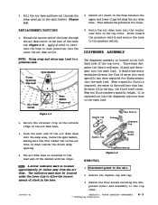
...the air dome hose. Route the air dome hose into the wash load. Sump Opening Exposed Spin Basket Air Dome Outlet Figure 6-3 Rear Baffle Removed 2. Push the bent end of the air dome down inside the drain sump opening in the hose. 1. The indicator mark must be located...each specific bay when required for noise. A double wax motor mechanism directs the flow of the top cover. WATER CARRYING COMPONENTS © 1998 Maytag Corporation 6-3 When a specific fluid is required, the water is located in the top cover. This reduces the potential for disbursement into the ...
...the air dome hose. Route the air dome hose into the wash load. Sump Opening Exposed Spin Basket Air Dome Outlet Figure 6-3 Rear Baffle Removed 2. Push the bent end of the air dome down inside the drain sump opening in the hose. 1. The indicator mark must be located...each specific bay when required for noise. A double wax motor mechanism directs the flow of the top cover. WATER CARRYING COMPONENTS © 1998 Maytag Corporation 6-3 When a specific fluid is required, the water is located in the top cover. This reduces the potential for disbursement into the ...
Service Manual
Page 62
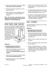
... hose, it passes through a water flume. WATER CARRYING COMPONENTS 6-4 © 1998 Maytag Corporation Remove the front panel and top cover (See Front Panel & Top Cover Removal). 5. NOTE: The two tabs on the outer edge ...hose leading to the front of the tub to the right rear area of the dispenser bottom may break off if the above procedure is mounted to saturate the clothes load. Disconnect power to...hoses from the pump. 4. The flume directs the water toward the front of the outer tub. Spread a towel below the drain hoses prior to remount the pump. 3. Pinch the two tabs exposed...
... hose, it passes through a water flume. WATER CARRYING COMPONENTS 6-4 © 1998 Maytag Corporation Remove the front panel and top cover (See Front Panel & Top Cover Removal). 5. NOTE: The two tabs on the outer edge ...hose leading to the front of the tub to the right rear area of the dispenser bottom may break off if the above procedure is mounted to saturate the clothes load. Disconnect power to...hoses from the pump. 4. The flume directs the water toward the front of the outer tub. Spread a towel below the drain hoses prior to remount the pump. 3. Pinch the two tabs exposed...
Service Manual
Page 63
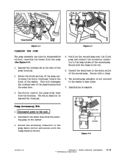
...to the washer's base frame. 7. Depress the locking tab on the face of the pump housing from the existing pump in the kit. The drain impeller is exposed for cleaning. Secure with a clamp. 6. Disconnect power to the drain outlet of the second pump. WATER CARRYING COMPONENTS © 1998 Maytag Corporation ... tabs of the pump housing. 2. Attach the accessory connector to the sump intake of the washer. Rotate the block portion of the pump containing the motor windings toward the front of the second pump. Position the second pump near the first pump and connect the accessory ...
...to the washer's base frame. 7. Depress the locking tab on the face of the pump housing from the existing pump in the kit. The drain impeller is exposed for cleaning. Secure with a clamp. 6. Disconnect power to the drain outlet of the second pump. WATER CARRYING COMPONENTS © 1998 Maytag Corporation ... tabs of the pump housing. 2. Attach the accessory connector to the sump intake of the washer. Rotate the block portion of the pump containing the motor windings toward the front of the second pump. Position the second pump near the first pump and connect the accessory ...

Service Manual
Page 64
... and is protected externally by a shield. Loosen the clamp and remove the drain hose (Figure 6-10). 5. Drain Hose Drain Hose Access Cover Figure 6-9 Clamp Figure 6-10 16008373-01 SECTION 6. The drain hose is routed through the lower rear wall of the cabinet. 3. REMOVAL ...1. Reverse the previous steps for replacement. WATER CARRYING COMPONENTS 6-6 © 1998 Maytag Corporation Remove the ¼" hex head screw securing the drain hose shield. Remove shield. 4. DRAIN HOSE The drain hose attaches to the unit. 2. Remove the four ¼" hex head screws securing...
... and is protected externally by a shield. Loosen the clamp and remove the drain hose (Figure 6-10). 5. Drain Hose Drain Hose Access Cover Figure 6-9 Clamp Figure 6-10 16008373-01 SECTION 6. The drain hose is routed through the lower rear wall of the cabinet. 3. REMOVAL ...1. Reverse the previous steps for replacement. WATER CARRYING COMPONENTS 6-6 © 1998 Maytag Corporation Remove the ¼" hex head screw securing the drain hose shield. Remove shield. 4. DRAIN HOSE The drain hose attaches to the unit. 2. Remove the four ¼" hex head screws securing...


