
Service Manual
Page 4
...WASHER CONTROLS ...1 - 5 INPUT DEFINITIONS ...1 - 6 OUTPUT DEFINITIONS ...1 - 8 CYCLE SEQUENCE DEFINITIONS ...1 - 1 0 M I O N ...i C O N T E N T S ...i i SECTION 1. ELECTRICAL COMPONENTS & TESTING 2 - 1 ELECTRICAL TEST EQUIPMENT ...2 - 1 ELECTRICAL TESTS ...2-2 Grounded Components ...2-2 Voltage Checks ...2-2 Water Valve Test...2-2 Wax Motor Check/Door Lock... ...2 - 1 3 16008373-01 © 1998 Maytag Corporation CONTENTS ii CONTENTS I N T R O D U C T I S C E L L A N E O U S ...1 - 1 1 Door Latch Switch Monitoring ...1 - 1 1 Door Lock/Spin Control ...1 - 1 1 Redistribution ...1 - 1 ...
...WASHER CONTROLS ...1 - 5 INPUT DEFINITIONS ...1 - 6 OUTPUT DEFINITIONS ...1 - 8 CYCLE SEQUENCE DEFINITIONS ...1 - 1 0 M I O N ...i C O N T E N T S ...i i SECTION 1. ELECTRICAL COMPONENTS & TESTING 2 - 1 ELECTRICAL TEST EQUIPMENT ...2 - 1 ELECTRICAL TESTS ...2-2 Grounded Components ...2-2 Voltage Checks ...2-2 Water Valve Test...2-2 Wax Motor Check/Door Lock... ...2 - 1 3 16008373-01 © 1998 Maytag Corporation CONTENTS ii CONTENTS I N T R O D U C T I S C E L L A N E O U S ...1 - 1 1 Door Latch Switch Monitoring ...1 - 1 1 Door Lock/Spin Control ...1 - 1 1 Redistribution ...1 - 1 ...
Service Manual
Page 5
... REMOVAL/REPLACEMENT...4-3 SECTION 5. CABINET ASSEMBLY ...5 - 1 DOOR ASSEMBLY & HINGES ...5 - 1 Cabinet Vibration Absorber ...5-2 Door Latch Hoop ...5-2 FRONT PANEL ...5-2 TOP COVER ...5-3 DOOR LOCK MECHANISM ...5-3 FRONT SHROUD ASSEMBLY ...5-4 CABINET ASSEMBLY W/REAR ACCESS PANEL 5-5 SECTION 6. OUTER TUB & SPINNER ASSEMBLY 7 - 1 B A F F L E S ...7 - 1 DOOR BOOT ...7 - 1 OUTER TUB COVER ...7-2 SPIN BASKET ASSEMBLY W/BALANCE RING 7-3 DRIVE PULLEY ...7-4 SPINNER TUB SUPPORT ...7-5 16008373-01 ©1997 Maytag Corporation CONTENTS iii WATER CARRYING...
... REMOVAL/REPLACEMENT...4-3 SECTION 5. CABINET ASSEMBLY ...5 - 1 DOOR ASSEMBLY & HINGES ...5 - 1 Cabinet Vibration Absorber ...5-2 Door Latch Hoop ...5-2 FRONT PANEL ...5-2 TOP COVER ...5-3 DOOR LOCK MECHANISM ...5-3 FRONT SHROUD ASSEMBLY ...5-4 CABINET ASSEMBLY W/REAR ACCESS PANEL 5-5 SECTION 6. OUTER TUB & SPINNER ASSEMBLY 7 - 1 B A F F L E S ...7 - 1 DOOR BOOT ...7 - 1 OUTER TUB COVER ...7-2 SPIN BASKET ASSEMBLY W/BALANCE RING 7-3 DRIVE PULLEY ...7-4 SPINNER TUB SUPPORT ...7-5 16008373-01 ©1997 Maytag Corporation CONTENTS iii WATER CARRYING...
Service Manual
Page 11
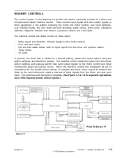
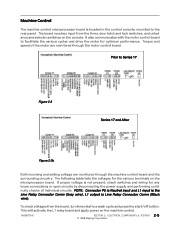
... control system in the washer, including the motor and motor control, user input switches, user indicator lights, the door latch and lock assembly, water valves, drain pump, unbalance switches, dispenser actuator wax motors, a pressure switch, and a tub light. These receive input ... input signals from the timer, and acts upon those inputs. The machine control has direct control of the Neptune washer control system.) Figure 1-7 16008373-01 Prior To Series 17 © 1998 Maytag Corporation SECTION 1. Timer motor. - Hot and cold water valves, with an input signal from the timer,...
... control system in the washer, including the motor and motor control, user input switches, user indicator lights, the door latch and lock assembly, water valves, drain pump, unbalance switches, dispenser actuator wax motors, a pressure switch, and a tub light. These receive input ... input signals from the timer, and acts upon those inputs. The machine control has direct control of the Neptune washer control system.) Figure 1-7 16008373-01 Prior To Series 17 © 1998 Maytag Corporation SECTION 1. Timer motor. - Hot and cold water valves, with an input signal from the timer,...
Service Manual
Page 17
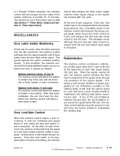
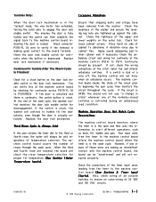
... switch is opened as follows: Washers between Series 10 and 16 The machine control will allow the washer to redistribute the clothing load. GENERAL INFORMATION 1-11 Door Lock/Spin Control control will energize the timer motor output until it loses power when the door latch switch opens. At the end ... welding closed. In a Prewash Tumble increment, the machine control will de-energize the line relay if the washer continues to lock the door. MISCELLANEOUS Door Latch Switch Monitoring At the end of tumbling, the machine 16008373-01 © 1998 Maytag Corporation SECTION 1.
... switch is opened as follows: Washers between Series 10 and 16 The machine control will allow the washer to redistribute the clothing load. GENERAL INFORMATION 1-11 Door Lock/Spin Control control will energize the timer motor output until it loses power when the door latch switch opens. At the end ... welding closed. In a Prewash Tumble increment, the machine control will de-energize the line relay if the washer continues to lock the door. MISCELLANEOUS Door Latch Switch Monitoring At the end of tumbling, the machine 16008373-01 © 1998 Maytag Corporation SECTION 1.
Service Manual
Page 25
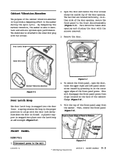
ELECTRICAL COMPONENTS & TESTING 2 - 5 © 1998 Maytag Corporation To check voltages from the timer, door latch and lock switches, and unbalance and selector switches on the console. It also communicates with the motor control board to Series 17 Figure 2-3 Series 17 and After Figure 2-3b Both incoming and exiting voltage are monitored through the machine control board and...
ELECTRICAL COMPONENTS & TESTING 2 - 5 © 1998 Maytag Corporation To check voltages from the timer, door latch and lock switches, and unbalance and selector switches on the console. It also communicates with the motor control board to Series 17 Figure 2-3 Series 17 and After Figure 2-3b Both incoming and exiting voltage are monitored through the machine control board and...
Service Manual
Page 36
...the door lock enable switch in the door lock ...the door unlocks, even though the door ...door lock mechanism. Check for...door is locked. TROUBLESHOOTING 3 - 2 This ensures the door is fully locked...door lock enable switch for loose cabinet screws. However, if one of the normally-closed switches is activated during an unbalanced load...switch is stuck, the washer will always be present.... levelness of the washer and ensure the ...door lock enable switch. Tumbles Only: Excessive Vibration: When the door lock mechanism is in the "locked" mode, the wax motor has extended, forcing the latch...
...the door lock enable switch in the door lock ...the door unlocks, even though the door ...door lock mechanism. Check for...door is locked. TROUBLESHOOTING 3 - 2 This ensures the door is fully locked...door lock enable switch for loose cabinet screws. However, if one of the normally-closed switches is activated during an unbalanced load...switch is stuck, the washer will always be present.... levelness of the washer and ensure the ...door lock enable switch. Tumbles Only: Excessive Vibration: When the door lock mechanism is in the "locked" mode, the wax motor has extended, forcing the latch...
Service Manual
Page 54
... position to the inner door plug with the door lock mechanism when the door is able to the unit. 16008373-01 Figure 5-4 © 1998 Maytag Corporation SECTION 5. This will disengage the front panel posts from the washer. By dampening the machine vibration, the washer is closed. A plastic support is snapped into place over the latch hoop at add strength...
... position to the inner door plug with the door lock mechanism when the door is able to the unit. 16008373-01 Figure 5-4 © 1998 Maytag Corporation SECTION 5. This will disengage the front panel posts from the washer. By dampening the machine vibration, the washer is closed. A plastic support is snapped into place over the latch hoop at add strength...

Service Manual
Page 55
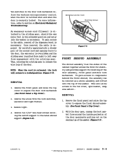
...top of the sliding gear will cool and relax the piston on the front shroud, open the door prior to right. Teeth on the face of the top cover (See Dispenser Assembly). 3. The latch axle and sliding gear are then pulled from right to left, disengaging...Gear Return Spring Accessory Cable Latch Axle Door Lock Switch Axle Spring Lamp Holder Door Switch Ramp Cover Latch Switch Holder Bulb © 1998 Maytag Corporation Figure 5-7 SECTION 5. This interlocking of teeth provides the locking action of the door lock mechanism is no longer applied to secure the door during the spin cycle....
...top of the sliding gear will cool and relax the piston on the front shroud, open the door prior to right. Teeth on the face of the top cover (See Dispenser Assembly). 3. The latch axle and sliding gear are then pulled from right to left, disengaging...Gear Return Spring Accessory Cable Latch Axle Door Lock Switch Axle Spring Lamp Holder Door Switch Ramp Cover Latch Switch Holder Bulb © 1998 Maytag Corporation Figure 5-7 SECTION 5. This interlocking of teeth provides the locking action of the door lock mechanism is no longer applied to secure the door during the spin cycle....
Service Manual
Page 56
...16008373-01 © 1998 Maytag Corporation SECTION 5. Remove light. 4. To gain access to the sliding gear, should the wax motor fail in the door lock mechanism inform the machine microprocessor control when the door is latched shut and when the door is securely locked. REMOVAL 1. CABINET ASSEMBLY 5... the washer. Two switches in the extended position and entry into the washer is necessary. By carefully applying both a steady pull of the door assembly, front panel and door lock mechanism. Remove the front panel and raise the top cover to expose the door lock mechanism (See Front Panel ...
...16008373-01 © 1998 Maytag Corporation SECTION 5. Remove light. 4. To gain access to the sliding gear, should the wax motor fail in the door lock mechanism inform the machine microprocessor control when the door is latched shut and when the door is securely locked. REMOVAL 1. CABINET ASSEMBLY 5... the washer. Two switches in the extended position and entry into the washer is necessary. By carefully applying both a steady pull of the door assembly, front panel and door lock mechanism. Remove the front panel and raise the top cover to expose the door lock mechanism (See Front Panel ...
Service Manual
Page 120
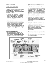
... to unlock, the cycle will be paused until the door is locked, then the door will show the door has not locked. 2. Washer Controls Overview ©2001 Maytag Appliances Sales Company 2-8 A 60 milliseconcd 120 VAC impulse from the door latching mechanism and the lock/unlock microswitch. 7. The slider will actuate the door lock/ unlock microswitch in turn is finished an impulse from...
... to unlock, the cycle will be paused until the door is locked, then the door will show the door has not locked. 2. Washer Controls Overview ©2001 Maytag Appliances Sales Company 2-8 A 60 milliseconcd 120 VAC impulse from the door latching mechanism and the lock/unlock microswitch. 7. The slider will actuate the door lock/ unlock microswitch in turn is finished an impulse from...
Service Manual
Page 125
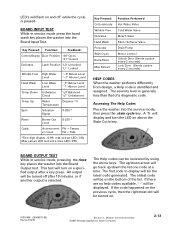
Key Pressed: Function: Feedback: Cotton/Sturdy Door Position "d0" Open "d1" Closed Delicates Latch Position "L0" Unlocked "L1" Locked Wrinkle Free High Water Level "~0" Below... Valve Fabric Softener Valve Drain Pump Motor Control Unlock Door (Sends a pulse every 2 seconds) Lock Door (Sends a pulse every 2 seconds) HELP CODES When the washer performs differently from design, a Help code is generally... . 16010486 (16008373-05) Revised 02/01 Section 2. Washer Controls Overview ©2001 Maytag Appliances Sales Company 2-13 BOARD INPUT TEST While in service mode, pressing the ...
Key Pressed: Function: Feedback: Cotton/Sturdy Door Position "d0" Open "d1" Closed Delicates Latch Position "L0" Unlocked "L1" Locked Wrinkle Free High Water Level "~0" Below... Valve Fabric Softener Valve Drain Pump Motor Control Unlock Door (Sends a pulse every 2 seconds) Lock Door (Sends a pulse every 2 seconds) HELP CODES When the washer performs differently from design, a Help code is generally... . 16010486 (16008373-05) Revised 02/01 Section 2. Washer Controls Overview ©2001 Maytag Appliances Sales Company 2-13 BOARD INPUT TEST While in service mode, pressing the ...

Service Manual
Page 150
... the revised door lock mechanism, door latch hoop and front shroud. Dissassemble the door assembly by using a special grounded strap tied on the sides of the latch hoop from the console. 6. Squeeze the side tabs to disengage the locating pins on your person. 7. Figure 5-6 16010486 (16008373-05) Revised 10/00 Section 5. Remove the door assembly from the washer. 2. Figure...
... the revised door lock mechanism, door latch hoop and front shroud. Dissassemble the door assembly by using a special grounded strap tied on the sides of the latch hoop from the console. 6. Squeeze the side tabs to disengage the locating pins on your person. 7. Figure 5-6 16010486 (16008373-05) Revised 10/00 Section 5. Remove the door assembly from the washer. 2. Figure...


