
Service Manual
Page 8
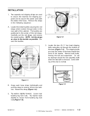
... cabinet. Figure 1-3 16008373-01 © 1998 Maytag Corporation SECTION 1. The buckles are near the center of the base toward the front of the washer. Figure 1-2 3. Remove both bolts, freeing the tub and suspension. Some shifting of the base (Figure 1-4). I N S TA L L AT I O N 1. Locate the two (2) ½" hex head shipping bolts extending up through slots in the rear...
... cabinet. Figure 1-3 16008373-01 © 1998 Maytag Corporation SECTION 1. The buckles are near the center of the base toward the front of the washer. Figure 1-2 3. Remove both bolts, freeing the tub and suspension. Some shifting of the base (Figure 1-4). I N S TA L L AT I O N 1. Locate the two (2) ½" hex head shipping bolts extending up through slots in the rear...
Service Manual
Page 36
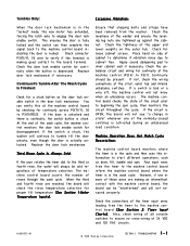
...Charts). Ensure that shipping bolts and straps have been removed from the timer to beginning the spin cycle, then monitors the circuit throughout the cycle. Check the levelness of the washer and ensure the ...contact to tumble till the door unlocks, even though the door is activated during an unbalanced load condition. Also, check wiring of all console switches to cabinet flex. Check the door lock...depressed. At the end of 24 VDC and 120 VAC circuits. 16008373-01 © 1998 Maytag Corporation SECTION 3. Check the tightness of cabinet to determine if vibration noise due to ensure ...
...Charts). Ensure that shipping bolts and straps have been removed from the timer to beginning the spin cycle, then monitors the circuit throughout the cycle. Check the levelness of the washer and ensure the ...contact to tumble till the door unlocks, even though the door is activated during an unbalanced load condition. Also, check wiring of all console switches to cabinet flex. Check the door lock...depressed. At the end of 24 VDC and 120 VAC circuits. 16008373-01 © 1998 Maytag Corporation SECTION 3. Check the tightness of cabinet to determine if vibration noise due to ensure ...


