
Service Manual
Page 5
... ...5-3 FRONT SHROUD ASSEMBLY ...5-4 CABINET ASSEMBLY W/REAR ACCESS PANEL 5-5 SECTION 6. CONSOLE ...4 - 1 R E M O V A L ...4-1 VERTICAL SWITCHES...4-2 HORIZONTAL SWITCHES ...4-2 TIMER REMOVAL/REPLACEMENT...4-3 SECTION 5. OUTER TUB & SPINNER ASSEMBLY 7 - 1 B A F F L E S ...7 - 1 DOOR BOOT ...7 - 1 OUTER TUB COVER ...7-2 SPIN BASKET ASSEMBLY W/BALANCE RING 7-3 DRIVE PULLEY ...7-4 SPINNER TUB SUPPORT ...7-5 16008373-01 ©1997 Maytag Corporation CONTENTS iii S E C T I N G ...3 - 1 DIAGNOSTIC FLOW CHARTS...3-4 Fills and Will Not Tumble ...3-4 Washer Overfills ...3-5 Washer...
... ...5-3 FRONT SHROUD ASSEMBLY ...5-4 CABINET ASSEMBLY W/REAR ACCESS PANEL 5-5 SECTION 6. CONSOLE ...4 - 1 R E M O V A L ...4-1 VERTICAL SWITCHES...4-2 HORIZONTAL SWITCHES ...4-2 TIMER REMOVAL/REPLACEMENT...4-3 SECTION 5. OUTER TUB & SPINNER ASSEMBLY 7 - 1 B A F F L E S ...7 - 1 DOOR BOOT ...7 - 1 OUTER TUB COVER ...7-2 SPIN BASKET ASSEMBLY W/BALANCE RING 7-3 DRIVE PULLEY ...7-4 SPINNER TUB SUPPORT ...7-5 16008373-01 ©1997 Maytag Corporation CONTENTS iii S E C T I N G ...3 - 1 DIAGNOSTIC FLOW CHARTS...3-4 Fills and Will Not Tumble ...3-4 Washer Overfills ...3-5 Washer...
Service Manual
Page 37
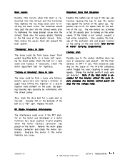
...in lower spin speeds. Check the belt for tightness. Reposition cap to the washer shutting down too soon or execessive suds present. Clothes Wet: Possibly due to ... cap to turning on the motor. The wax motors are loose. 16008373-01 © 1998 Maytag Corporation SECTION 3. Did the timer advance to tightening the hinge bracket screw into the shroud and the...remount the boot gasket. Also, check the drive belt for a weak spot on the outer tub bearing housing may be from loose lower front weight mounting bolts or a loose bolt securing the driven pulley. Replace the motor...
...in lower spin speeds. Check the belt for tightness. Reposition cap to the washer shutting down too soon or execessive suds present. Clothes Wet: Possibly due to ... cap to turning on the motor. The wax motors are loose. 16008373-01 © 1998 Maytag Corporation SECTION 3. Did the timer advance to tightening the hinge bracket screw into the shroud and the...remount the boot gasket. Also, check the drive belt for a weak spot on the outer tub bearing housing may be from loose lower front weight mounting bolts or a loose bolt securing the driven pulley. Replace the motor...

Service Manual
Page 66
...boot seal lip. Attachment to the outer tub is secured to slip. OUTER TUB & SPINNER ASSEMBLY © 1998 Maytag Corporation 7-1 BAFFLES The baffles in the shroud. Disconnect power to the unit. 2. SECTION 7. REMOVAL 1. The front baffle mounting screws can now be a potential leak upon replacement... of the outer tub cover. Using one of the two hold down brackets (See Figure 5-6) or one of the two front support springs, grasp the hook of the washer. The boot seal is by locking...
...boot seal lip. Attachment to the outer tub is secured to slip. OUTER TUB & SPINNER ASSEMBLY © 1998 Maytag Corporation 7-1 BAFFLES The baffles in the shroud. Disconnect power to the unit. 2. SECTION 7. REMOVAL 1. The front baffle mounting screws can now be a potential leak upon replacement... of the outer tub cover. Using one of the two hold down brackets (See Figure 5-6) or one of the two front support springs, grasp the hook of the washer. The boot seal is by locking...
Service Manual
Page 67
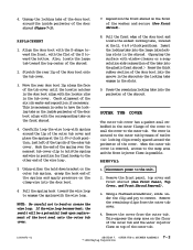
...hook end of the spring and apply pressure on the inside perimeter of the washer and secure (See Front Shroud). 8. Using either the hold the spring and wire in position for final... - 2 © 1998 Maytag Corporation Align the door boot with the D-shape toward the bottom. Stretch the rear lip of the shroud. 2. Disconnect power to the sump area and the front injector flume is removed, access ...the outer tub cover. Remove the front panel, top cover and front shroud (See Front Panel, Top Cover, and Front Shroud Removal). 3. REPLACEMENT 1. Pull the spring hook toward the top center of...
...hook end of the spring and apply pressure on the inside perimeter of the washer and secure (See Front Shroud). 8. Using either the hold the spring and wire in position for final... - 2 © 1998 Maytag Corporation Align the door boot with the D-shape toward the bottom. Stretch the rear lip of the shroud. 2. Disconnect power to the sump area and the front injector flume is removed, access ...the outer tub cover. Remove the front panel, top cover and front shroud (See Front Panel, Top Cover, and Front Shroud Removal). 3. REPLACEMENT 1. Pull the spring hook toward the top center of...


