
Service Manual
Page 5
...Maytag Corporation CONTENTS iii CONSOLE ...4 - 1 R E M O V A L ...4-1 VERTICAL SWITCHES...4-2 HORIZONTAL SWITCHES ...4-2 TIMER REMOVAL/REPLACEMENT...4-3 SECTION 5. CABINET ASSEMBLY ...5 - 1 DOOR ASSEMBLY & HINGES ...5 - 1 Cabinet Vibration Absorber ...5-2 Door Latch Hoop ...5-2 FRONT PANEL ...5-2 TOP COVER ...5-3 DOOR LOCK MECHANISM ...5-3 FRONT... ASSEMBLY ...6-3 FRONT WATER FLUME INJECTOR...6-4 PUMP ASSEMBLY ...6-4 Pump Accessory ...6-5 DRAIN HOSE ...6-6 SECTION 7. S E C T I N G ...3 - 1 DIAGNOSTIC FLOW CHARTS...3-4 Fills and Will Not Tumble ...3-4 Washer Overfills ...3-5 Washer Will Not ...
...Maytag Corporation CONTENTS iii CONSOLE ...4 - 1 R E M O V A L ...4-1 VERTICAL SWITCHES...4-2 HORIZONTAL SWITCHES ...4-2 TIMER REMOVAL/REPLACEMENT...4-3 SECTION 5. CABINET ASSEMBLY ...5 - 1 DOOR ASSEMBLY & HINGES ...5 - 1 Cabinet Vibration Absorber ...5-2 Door Latch Hoop ...5-2 FRONT PANEL ...5-2 TOP COVER ...5-3 DOOR LOCK MECHANISM ...5-3 FRONT... ASSEMBLY ...6-3 FRONT WATER FLUME INJECTOR...6-4 PUMP ASSEMBLY ...6-4 Pump Accessory ...6-5 DRAIN HOSE ...6-6 SECTION 7. S E C T I N G ...3 - 1 DIAGNOSTIC FLOW CHARTS...3-4 Fills and Will Not Tumble ...3-4 Washer Overfills ...3-5 Washer Will Not ...
Service Manual
Page 7
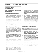
...drain standpipe is in excess of 5 feet above floor level, install pump accessory kit, part number 22002136. • This unit is required to the washer. 2. This allows quick access for electrical service. • Standpipe Drain...© 1998 Maytag Corporation SECTION 1. UNCRATING INSTRUCTIONS NOTE: The following steps must accept 1½" O.D. may need to be performed in marked areas of 20 - 120 P.S.I . drain hose. Carefully ... back of the washer. Remove the accessory package from the outside of the washer. Remove the crate bottom from unbalanced load situations.
...drain standpipe is in excess of 5 feet above floor level, install pump accessory kit, part number 22002136. • This unit is required to the washer. 2. This allows quick access for electrical service. • Standpipe Drain...© 1998 Maytag Corporation SECTION 1. UNCRATING INSTRUCTIONS NOTE: The following steps must accept 1½" O.D. may need to be performed in marked areas of 20 - 120 P.S.I . drain hose. Carefully ... back of the washer. Remove the accessory package from the outside of the washer. Remove the crate bottom from unbalanced load situations.
Service Manual
Page 11
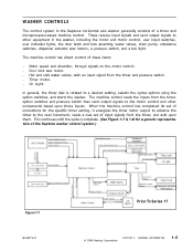
...drain pump, unbalance switches, dispenser actuator wax motors, a pressure switch, and a tub light. Hot and cold water valves, with an input signal from the timer, and acts upon those inputs. These receive input signals and send output signals to the motor control and other equipment in the Neptune horizontal axis washer... the timer and pressure switch. - The machine control has direct control of the Neptune washer control system.) Figure 1-7 16008373-01 Prior To Series 17 © 1998 Maytag Corporation SECTION 1. The machine control reads the inputs from the timer, option switches ...
...drain pump, unbalance switches, dispenser actuator wax motors, a pressure switch, and a tub light. Hot and cold water valves, with an input signal from the timer, and acts upon those inputs. These receive input signals and send output signals to the motor control and other equipment in the Neptune horizontal axis washer... the timer and pressure switch. - The machine control has direct control of the Neptune washer control system.) Figure 1-7 16008373-01 Prior To Series 17 © 1998 Maytag Corporation SECTION 1. The machine control reads the inputs from the timer, option switches ...
Service Manual
Page 23
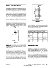
... a series of the electrical schematic enclosed in the washer console. 16008373-01 SECTION 2. As illustrated, timer contact for the drain circuit (Figure 2-2) by tracing down the side of the complete drain circuit can be performed. Figure 2-1 You can be pulled and the individual contacts for the various circuits can identify the wire for the drain pump...
... a series of the electrical schematic enclosed in the washer console. 16008373-01 SECTION 2. As illustrated, timer contact for the drain circuit (Figure 2-2) by tracing down the side of the complete drain circuit can be performed. Figure 2-1 You can be pulled and the individual contacts for the various circuits can identify the wire for the drain pump...
Service Manual
Page 62
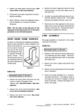
...load. Rotate the pump assembly in the hoses and sump area. 3. Remove the front panel and raise the top cover to replace the injector. The support legs of the outer tub spout and press the injector into the tub. WATER CARRYING COMPONENTS 6-4 © 1998 Maytag... the water toward the front of the outer tub through the hose, it passes through a water flume. Figure 6-5 REMOVAL 1. Spread a towel below the drain hoses prior to the dispenser assembly. 6. Remove the wiring harness from the pump. 4. Remove the front shroud assembly (See Front Shroud Assembly Removal). 4....
...load. Rotate the pump assembly in the hoses and sump area. 3. Remove the front panel and raise the top cover to replace the injector. The support legs of the outer tub spout and press the injector into the tub. WATER CARRYING COMPONENTS 6-4 © 1998 Maytag... the water toward the front of the outer tub through the hose, it passes through a water flume. Figure 6-5 REMOVAL 1. Spread a towel below the drain hoses prior to the dispenser assembly. 6. Remove the wiring harness from the pump. 4. Remove the front shroud assembly (See Front Shroud Assembly Removal). 4....
Service Manual
Page 63
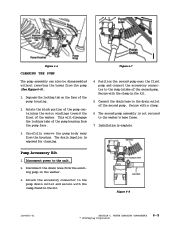
...-01 SECTION 6. Rotate the block portion of the pump containing the motor windings toward the front of the pump housing. 2. Disconnect the drain hose from the pump face. 4. Installation is exposed for cleaning. Attach the accessory connector to the pump drain outlet and secure with the clamp in the washer. 3. This will disengage the locking tabs of the...
...-01 SECTION 6. Rotate the block portion of the pump containing the motor windings toward the front of the pump housing. 2. Disconnect the drain hose from the pump face. 4. Installation is exposed for cleaning. Attach the accessory connector to the pump drain outlet and secure with the clamp in the washer. 3. This will disengage the locking tabs of the...

Service Manual
Page 64
... is routed through the lower rear wall of the drain hose to the pump. Reverse the previous steps for replacement. DRAIN HOSE The drain hose attaches to the pump and is protected externally by a shield. REMOVAL 1. With access into the machine compartment, spread a towel .... 3. Drain Hose Drain Hose Access Cover Figure 6-9 Clamp Figure 6-10 16008373-01 SECTION 6. Remove the four ¼" hex head screws securing the access panel to the unit. 2. Remove the ¼" hex head screw securing the drain hose shield. WATER CARRYING COMPONENTS 6-6 © 1998 Maytag Corporation
... is routed through the lower rear wall of the drain hose to the pump. Reverse the previous steps for replacement. DRAIN HOSE The drain hose attaches to the pump and is protected externally by a shield. REMOVAL 1. With access into the machine compartment, spread a towel .... 3. Drain Hose Drain Hose Access Cover Figure 6-9 Clamp Figure 6-10 16008373-01 SECTION 6. Remove the four ¼" hex head screws securing the access panel to the unit. 2. Remove the ¼" hex head screw securing the drain hose shield. WATER CARRYING COMPONENTS 6-6 © 1998 Maytag Corporation
Service Manual
Page 89
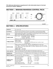
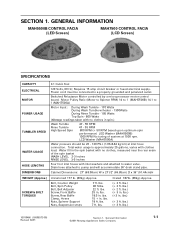
... Belt Adjuster Screw, Front Baffle Screw, Rear ... Motor Pulley Ratio (Motor to Spinner RPM) 14 to pump and will accommodate 36" drain stand pipe. lbs.) (+ 3 in . lbs.) ...load. lbs. 18 in . MAH4000/MAH5500A CONTROL FACIA SECTION 2. SPECIFICATIONS CAPACITY ELECTRICAL MOTOR POWER USAGE TUMBLER SPEED WATER USAGE HOSE LENGTHS DIMENSIONS 3.1 Cubic Feet 120 Volts, 60 Hz; lbs. 90 in . lbs. 30 in . Drain...Maytag Appliances Sales Company Water fill in the spin basket with inlet washers and attached to a properly grounded and polarized outlet. Cabinet Dimensions: 27...
... Belt Adjuster Screw, Front Baffle Screw, Rear ... Motor Pulley Ratio (Motor to Spinner RPM) 14 to pump and will accommodate 36" drain stand pipe. lbs.) (+ 3 in . lbs.) ...load. lbs. 18 in . MAH4000/MAH5500A CONTROL FACIA SECTION 2. SPECIFICATIONS CAPACITY ELECTRICAL MOTOR POWER USAGE TUMBLER SPEED WATER USAGE HOSE LENGTHS DIMENSIONS 3.1 Cubic Feet 120 Volts, 60 Hz; lbs. 90 in . lbs. 30 in . Drain...Maytag Appliances Sales Company Water fill in the spin basket with inlet washers and attached to a properly grounded and polarized outlet. Cabinet Dimensions: 27...
Service Manual
Page 90
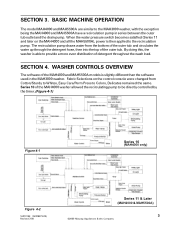
... used in series between the outer tub outlet and the drain pump. The recirculation pump draws water from Cotton/Sturdy to Whites, Easy Care/Perm Press to the recirculation pump. By doing this, the washer is then applied to Colors, Delicates remained the same. SECTION 4. WASHER CONTROLS OVERVIEW The software of detergent throughout the wash load. BASIC MACHINE...
... used in series between the outer tub outlet and the drain pump. The recirculation pump draws water from Cotton/Sturdy to Whites, Easy Care/Perm Press to the recirculation pump. By doing this, the washer is then applied to Colors, Delicates remained the same. SECTION 4. WASHER CONTROLS OVERVIEW The software of detergent throughout the wash load. BASIC MACHINE...

Service Manual
Page 97
...TOP VIEW) 5. Remove the front panel. 3. Lay a towel under the tub to pump hose and loosen the clamp on the pump connection to the machine. 2. DISPENSER FLUME DISPENSER BOTTOM DETERGENT WASH INLET HOSE RECIRCULATION PUMP The Recirculation Pump is accessible from the front or the rear of the ...16008373-03) 10 Revised 7/00 ©2000 Maytag Appliances Sales Company Lift the recirculation pump at an angle to disengage the locating tab of the machine. The pump is connected in series with the outer tub pump hose and the drain hose. (See Figure 8-4) FABRIC SOFTENER INLET HOSE...
...TOP VIEW) 5. Remove the front panel. 3. Lay a towel under the tub to pump hose and loosen the clamp on the pump connection to the machine. 2. DISPENSER FLUME DISPENSER BOTTOM DETERGENT WASH INLET HOSE RECIRCULATION PUMP The Recirculation Pump is accessible from the front or the rear of the ...16008373-03) 10 Revised 7/00 ©2000 Maytag Appliances Sales Company Lift the recirculation pump at an angle to disengage the locating tab of the machine. The pump is connected in series with the outer tub pump hose and the drain hose. (See Figure 8-4) FABRIC SOFTENER INLET HOSE...
Service Manual
Page 109
...no clothes in . Drain hose attached to a properly grounded and polarized outlet. Bolt, Counter Weight Bolt, Spin Pulley Bolt, Belt Adjuster Screw, Front Baffle Screw, Rear Baffle.... 38 ft.lbs. 22 ft. LCD Washer (MAH7500A) Water pressure should be connected to pump and will accommodate 36" drain stand pipe. Cabinet Dimensions: 27" (68.58cm) W x 271/2" (69... Volts, 60 Hz; lbs. 25 in . General Information ©2001 Maytag Appliances Sales Company 1-1 lbs. 7 ft. lbs.) (+ 3 ft. ...based upon optimum spin performance) LED Washer (MAH5500B) 1000 RPM No tuning of the spin basket ...
...no clothes in . Drain hose attached to a properly grounded and polarized outlet. Bolt, Counter Weight Bolt, Spin Pulley Bolt, Belt Adjuster Screw, Front Baffle Screw, Rear Baffle.... 38 ft.lbs. 22 ft. LCD Washer (MAH7500A) Water pressure should be connected to pump and will accommodate 36" drain stand pipe. Cabinet Dimensions: 27" (68.58cm) W x 271/2" (69... Volts, 60 Hz; lbs. 25 in . General Information ©2001 Maytag Appliances Sales Company 1-1 lbs. 7 ft. lbs.) (+ 3 ft. ...based upon optimum spin performance) LED Washer (MAH5500B) 1000 RPM No tuning of the spin basket ...
Service Manual
Page 110
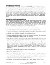
... is turned off. Fabric selection impacts tumble pattern. The exception would have a 7/3 tumble pattern. General Information ©2001 Maytag Appliances Sales Company 1-2 The door lock mechanism was changed to a sensorless system, thus eliminating the tach sensor in the motor...pump, thus eliminating the airdome hose. Once filled, the tumble pattern and the total wash time depends on for 30 seconds after the water reaches the wash fill level. Toward the end of the wash and rinse spin, the cold water valve will be dispensed. 8) The washer will then drain and spin. 9) The washer...
... is turned off. Fabric selection impacts tumble pattern. The exception would have a 7/3 tumble pattern. General Information ©2001 Maytag Appliances Sales Company 1-2 The door lock mechanism was changed to a sensorless system, thus eliminating the tach sensor in the motor...pump, thus eliminating the airdome hose. Once filled, the tumble pattern and the total wash time depends on for 30 seconds after the water reaches the wash fill level. Toward the end of the wash and rinse spin, the cold water valve will be dispensed. 8) The washer will then drain and spin. 9) The washer...

Service Manual
Page 112
... the rinses are the same as the wash temperature. speed. General Information ©2001 Maytag Appliances Sales Company 1-4 ON/OFF SEQUENCE OF PUMP DURING SPIN CYCLE Spin Speed Drain Pump a) =540 rpm and 30 seconds after 15 second on the user selections. The following... and C/C N W/W Y (heavy, normal, and light only, quick is the same as if stain cycle was not selected. The water temperature entering the washer during final spin Off until machine reaches 300 RPM and then on until next step in the cycle 16010486 (16008373-05) Revised 02/01 Section...
... the rinses are the same as the wash temperature. speed. General Information ©2001 Maytag Appliances Sales Company 1-4 ON/OFF SEQUENCE OF PUMP DURING SPIN CYCLE Spin Speed Drain Pump a) =540 rpm and 30 seconds after 15 second on the user selections. The following... and C/C N W/W Y (heavy, normal, and light only, quick is the same as if stain cycle was not selected. The water temperature entering the washer during final spin Off until machine reaches 300 RPM and then on until next step in the cycle 16010486 (16008373-05) Revised 02/01 Section...
Service Manual
Page 125
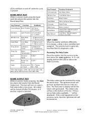
...washer into the Board Output test. Key Pressed: Cotton/sturdy Wrinkle Free Delicates Hand Wash Presoaks Stain Cycle Extra Rinse Max Extract Function Performed Hot Water Valve Cold Water Valve Bleach Valve Fabric Softener Valve Drain Pump... Motor Control Unlock Door (Sends a pulse every 2 seconds) Lock Door (Sends a pulse every 2 seconds) HELP CODES When the washer...latest code generated. Accessing The Help Codes Place the washer into the Board Input Test. The first code to ...in service mode press the hand wash key places the washer into the service mode, then press the stain cycle ...
...washer into the Board Output test. Key Pressed: Cotton/sturdy Wrinkle Free Delicates Hand Wash Presoaks Stain Cycle Extra Rinse Max Extract Function Performed Hot Water Valve Cold Water Valve Bleach Valve Fabric Softener Valve Drain Pump... Motor Control Unlock Door (Sends a pulse every 2 seconds) Lock Door (Sends a pulse every 2 seconds) HELP CODES When the washer...latest code generated. Accessing The Help Codes Place the washer into the Board Input Test. The first code to ...in service mode press the hand wash key places the washer into the service mode, then press the stain cycle ...
Service Manual
Page 131
...Fill hoses are contrary to aid in identifying which components may have been initially actuated. Check pump for restricted drain system, kinked/plugged drain hose or pump. non-critical condition Identify where specifically in redistribution cycle. Low water level contacts of pressure ... is being demanded by machine control board. non-critical condition. Informative only; (LED washer only) Informative only; If random, suspect incoming power supply to be Taken Unbalance load condition existed during a spin. Locked rotor condition during initial ramp up or spin cycle...
...Fill hoses are contrary to aid in identifying which components may have been initially actuated. Check pump for restricted drain system, kinked/plugged drain hose or pump. non-critical condition Identify where specifically in redistribution cycle. Low water level contacts of pressure ... is being demanded by machine control board. non-critical condition. Informative only; (LED washer only) Informative only; If random, suspect incoming power supply to be Taken Unbalance load condition existed during a spin. Locked rotor condition during initial ramp up or spin cycle...
Service Manual
Page 134
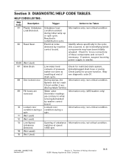
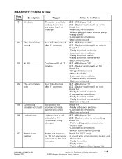
... for : •Restricted drain system •Kinked/plugged drain hose or pump •Faulty pump •Loose wire connections •Bad control board LED - Display washer will not drain Check for : •... •Pressure switch contacts •Bad control board LED - Teardown & Wiring Information ©2001 Maytag Appliances Sales Company 3-4 Will display "nF" LCD - Display motor is not heating Heater has been...failed to lock after 11 attempts 05 Continuous See section for unbalanced circuit unbalanced loads. (During spin only) 06 Locked rotor Locked rotor is still locked after...
... for : •Restricted drain system •Kinked/plugged drain hose or pump •Faulty pump •Loose wire connections •Bad control board LED - Display washer will not drain Check for : •... •Pressure switch contacts •Bad control board LED - Teardown & Wiring Information ©2001 Maytag Appliances Sales Company 3-4 Will display "nF" LCD - Display motor is not heating Heater has been...failed to lock after 11 attempts 05 Continuous See section for unbalanced circuit unbalanced loads. (During spin only) 06 Locked rotor Locked rotor is still locked after...
Service Manual
Page 139
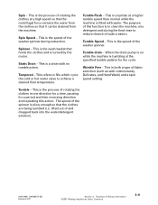
... Hand Wash) and a spin speed setting. Teardown & Wiring Information ©2001 Maytag Appliances Sales Company 3-9 Tempered – This refers to fills which cycle the cold or hot water valve to reduce chance of the washer spinner. Wrinkle Free – This is both a type of rotating the clothes...the machine, mix detergent and during extraction. Tumble drain – When the drain pump is on while the machine is tumbling at a higher tumble speed than normal while the machine is filled with no tumble action. lifted out of the washer spinner during the final rinse to achieve a ...
... Hand Wash) and a spin speed setting. Teardown & Wiring Information ©2001 Maytag Appliances Sales Company 3-9 Tempered – This refers to fills which cycle the cold or hot water valve to reduce chance of the washer spinner. Wrinkle Free – This is both a type of rotating the clothes...the machine, mix detergent and during extraction. Tumble drain – When the drain pump is on while the machine is tumbling at a higher tumble speed than normal while the machine is filled with no tumble action. lifted out of the washer spinner during the final rinse to achieve a ...
Service Manual
Page 143
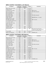
...Door lock switch input P2(3) P3(8) 24 VDC Door switch input P8(1) P8(2) 120 VAC Door unlock output P8(2) P8(2) 120 VAC Drain pump output P8(4) P8(2) 120 VAC (Open) P6(2) P8(1) High water level - input P1(8) P8(2) 120 VAC Hot water valve ...Washer) Description Bleach water valve output Chassis Ground Cold water valve output Door Lock output Door lock switch input Door switch input Door unlock output Drain pump output Heater - input Hot water valve output L1 to machine control board L1 to motor control Lower water level - Electrical Components & Testing ©2001 Maytag...
...Door lock switch input P2(3) P3(8) 24 VDC Door switch input P8(1) P8(2) 120 VAC Door unlock output P8(2) P8(2) 120 VAC Drain pump output P8(4) P8(2) 120 VAC (Open) P6(2) P8(1) High water level - input P1(8) P8(2) 120 VAC Hot water valve ...Washer) Description Bleach water valve output Chassis Ground Cold water valve output Door Lock output Door lock switch input Door switch input Door unlock output Drain pump output Heater - input Hot water valve output L1 to machine control board L1 to motor control Lower water level - Electrical Components & Testing ©2001 Maytag...


