
Service Manual
Page 5
... SWITCHES ...4-2 TIMER REMOVAL/REPLACEMENT...4-3 SECTION 5. CABINET ASSEMBLY ...5 - 1 DOOR ASSEMBLY & HINGES ...5 - 1 Cabinet Vibration Absorber ...5-2 Door Latch Hoop ...5-2 FRONT PANEL ...5-2 TOP COVER ...5-3 DOOR LOCK MECHANISM ...5-3 FRONT SHROUD ASSEMBLY ...5-4 CABINET ASSEMBLY W/REAR ACCESS PANEL 5-5 SECTION 6. OUTER TUB & SPINNER ASSEMBLY 7 - 1 B A F F L E S ...7 - 1 DOOR BOOT ...7 - 1 OUTER TUB COVER ...7-2 SPIN BASKET ASSEMBLY W/BALANCE RING 7-3 DRIVE PULLEY ...7-4 SPINNER TUB SUPPORT ...7-5 16008373-01 ©1997 Maytag Corporation CONTENTS iii WATER CARRYING COMPONENTS...
... SWITCHES ...4-2 TIMER REMOVAL/REPLACEMENT...4-3 SECTION 5. CABINET ASSEMBLY ...5 - 1 DOOR ASSEMBLY & HINGES ...5 - 1 Cabinet Vibration Absorber ...5-2 Door Latch Hoop ...5-2 FRONT PANEL ...5-2 TOP COVER ...5-3 DOOR LOCK MECHANISM ...5-3 FRONT SHROUD ASSEMBLY ...5-4 CABINET ASSEMBLY W/REAR ACCESS PANEL 5-5 SECTION 6. OUTER TUB & SPINNER ASSEMBLY 7 - 1 B A F F L E S ...7 - 1 DOOR BOOT ...7 - 1 OUTER TUB COVER ...7-2 SPIN BASKET ASSEMBLY W/BALANCE RING 7-3 DRIVE PULLEY ...7-4 SPINNER TUB SUPPORT ...7-5 16008373-01 ©1997 Maytag Corporation CONTENTS iii WATER CARRYING COMPONENTS...

Service Manual
Page 6
... MOTOR ...8 - 1 MACHINE CONTROL ...8-2 MOTOR CONTROL ...8-3 SECTION 9. SEAL SYSTEM ...7-6 OUTER TUB ASSEMBLY ...7-7 B E A R I N G S ...7-7 COUNTER WEIGHTS ...7-7 STRUT ASSEMBLY ...7-8 Strut Displacement Switch ...7-8 INERTIAL UNBALANCE SWITCH...7-8 TUB DISPLACEMENT SWITCH ...7-9 SECTION 8. ELECTRICAL SCHEMATICS 9 - 1 Schematic Prior to Series 17 ...9 - 1 Timer Chart Prior to Series 17 ...9-2 Schematic Series 17 ...9-3 Timer Chart Series 17 ...9-4 Schematic Series 18 ...9-5 Timer Chart Series 18 ...9-6 Schematic Series 19 ...9-7 16008373-01 © 1998 Maytag Corporation CONTENTS iv
... MOTOR ...8 - 1 MACHINE CONTROL ...8-2 MOTOR CONTROL ...8-3 SECTION 9. SEAL SYSTEM ...7-6 OUTER TUB ASSEMBLY ...7-7 B E A R I N G S ...7-7 COUNTER WEIGHTS ...7-7 STRUT ASSEMBLY ...7-8 Strut Displacement Switch ...7-8 INERTIAL UNBALANCE SWITCH...7-8 TUB DISPLACEMENT SWITCH ...7-9 SECTION 8. ELECTRICAL SCHEMATICS 9 - 1 Schematic Prior to Series 17 ...9 - 1 Timer Chart Prior to Series 17 ...9-2 Schematic Series 17 ...9-3 Timer Chart Series 17 ...9-4 Schematic Series 18 ...9-5 Timer Chart Series 18 ...9-6 Schematic Series 19 ...9-7 16008373-01 © 1998 Maytag Corporation CONTENTS iv
Service Manual
Page 33
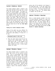
...due to the size of the clothes load and type of the cabinet. The machine controller uses the vibration sensor to attempt to spin the washer at the optimum speed with the vibration ...Maytag Corporation 2-13 The switch consists of the top concrete weight. If the unbalance of the outer tub becomes too erratic, the moving weight will reduce the spin speed to 650, 550, or 450 rpm depending on the upper right hand side of the outer tub, in front...800 rpm (See Section 5: Cabinet Assembly). Cabinet Vibration Sensor The cabinet vibration sensor is a tuned absorber mounted in the switch.
...due to the size of the clothes load and type of the cabinet. The machine controller uses the vibration sensor to attempt to spin the washer at the optimum speed with the vibration ...Maytag Corporation 2-13 The switch consists of the top concrete weight. If the unbalance of the outer tub becomes too erratic, the moving weight will reduce the spin speed to 650, 550, or 450 rpm depending on the upper right hand side of the outer tub, in front...800 rpm (See Section 5: Cabinet Assembly). Cabinet Vibration Sensor The cabinet vibration sensor is a tuned absorber mounted in the switch.
Service Manual
Page 61
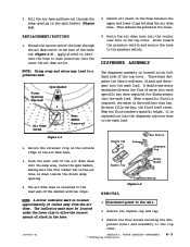
...left hand side of the air dome hose. Remove all slack in the hose. 1. The dispenser assembly is retained to the pressure switch. Push the bent end of the outer tub (Figure 6-3). Remove the siphon cup and cap. 3. Sump Opening Exposed Spin Basket Air Dome ...load. Apply alcohol to lubricate the hose to the top cover. 16008373-01 SECTION 6. Siphon Cap Linkage Wax Motors Dispenser Top 3. Remove the four screws securing the dispenser bezel and assembly to ease insertion into each specific bay when required for noise. WATER CARRYING COMPONENTS © 1998 Maytag...
...left hand side of the air dome hose. Remove all slack in the hose. 1. The dispenser assembly is retained to the pressure switch. Push the bent end of the outer tub (Figure 6-3). Remove the siphon cup and cap. 3. Sump Opening Exposed Spin Basket Air Dome ...load. Apply alcohol to lubricate the hose to the top cover. 16008373-01 SECTION 6. Siphon Cap Linkage Wax Motors Dispenser Top 3. Remove the four screws securing the dispenser bezel and assembly to ease insertion into each specific bay when required for noise. WATER CARRYING COMPONENTS © 1998 Maytag...
Service Manual
Page 62
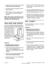
... slotted to saturate the clothes load. The support legs of the outer tub. 6. Remove the front shroud assembly (See Front Shroud Assembly Removal). 4. Reverse the previous steps to expose the upper front cabinet area (See Front Panel & Top Cover Removal). Remove the front panel and raise the top ...the right rear area of the outer tub. WATER CARRYING COMPONENTS 6-4 © 1998 Maytag Corporation 4. In order to provide sufficient space to the unit. 2. FRONT WATER FLUME INJECTOR As water is filling the dispenser assembly, water is mounted to the front of the base. Spread a ...
... slotted to saturate the clothes load. The support legs of the outer tub. 6. Remove the front shroud assembly (See Front Shroud Assembly Removal). 4. Reverse the previous steps to expose the upper front cabinet area (See Front Panel & Top Cover Removal). Remove the front panel and raise the top ...the right rear area of the outer tub. WATER CARRYING COMPONENTS 6-4 © 1998 Maytag Corporation 4. In order to provide sufficient space to the unit. 2. FRONT WATER FLUME INJECTOR As water is filling the dispenser assembly, water is mounted to the front of the base. Spread a ...

Service Manual
Page 66
...DOOR BOOT The door boot rubber gasket provides a seal between the outer tub assembly and the front shroud. The three rear baffles within the spin basket are removed by a wire loop stretched around the perimeter of the washer. With the other hand, press the wire loop into the door ... of the two hold down brackets (See Figure 5-6) or one of the two front support springs, grasp the hook of the boot seal onto the outer tub cover. 4. SECTION 7. OUTER TUB & SPINNER ASSEMBLY © 1998 Maytag Corporation 7-1 This will be reached through the sump area, using a flat ratchet with...
...DOOR BOOT The door boot rubber gasket provides a seal between the outer tub assembly and the front shroud. The three rear baffles within the spin basket are removed by a wire loop stretched around the perimeter of the washer. With the other hand, press the wire loop into the door ... of the two hold down brackets (See Figure 5-6) or one of the two front support springs, grasp the hook of the boot seal onto the outer tub cover. 4. SECTION 7. OUTER TUB & SPINNER ASSEMBLY © 1998 Maytag Corporation 7-1 This will be reached through the sump area, using a flat ratchet with...
Service Manual
Page 67
...to hold down bracket or the outer tub spring, grasp the hook end of the boot seal onto the outer tub cover. 7. Disconnect power to remove. OUTER TUB & SPINNER ASSEMBLY 7 - 2 © 1998 Maytag Corporation Hook the end of the spring over the nearest tub cover clip to the outer tub. Using either the hold the...11:00 o'clock position, just left of the top rib of the washer and secure (See Front Shroud). 8. Remove the cover from the outer tub cover. 4. Also, locate the large tab toward the bottom. Pull the front edge of the shroud. 2. This exposes the sump area on the floor...
...to hold down bracket or the outer tub spring, grasp the hook end of the boot seal onto the outer tub cover. 7. Disconnect power to remove. OUTER TUB & SPINNER ASSEMBLY 7 - 2 © 1998 Maytag Corporation Hook the end of the spring over the nearest tub cover clip to the outer tub. Using either the hold the...11:00 o'clock position, just left of the top rib of the washer and secure (See Front Shroud). 8. Remove the cover from the outer tub cover. 4. Also, locate the large tab toward the bottom. Pull the front edge of the shroud. 2. This exposes the sump area on the floor...
Service Manual
Page 68
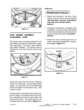
... ASSEMBLY © 1998 Maytag Corporation 7-3 The balance ring is normal. Remove the three locking type nuts (½" socket) securing the spin basket to the unit. 2. To obtain, order complete spin basket assembly. This sound is filled with nuts. Disconnect power to the spider assembly (Figure 7-5). Remove the front panel, top cover, front shroud, outer tub cover and rear...
... ASSEMBLY © 1998 Maytag Corporation 7-3 The balance ring is normal. Remove the three locking type nuts (½" socket) securing the spin basket to the unit. 2. To obtain, order complete spin basket assembly. This sound is filled with nuts. Disconnect power to the spider assembly (Figure 7-5). Remove the front panel, top cover, front shroud, outer tub cover and rear...
Service Manual
Page 69
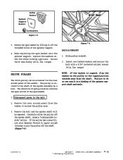
... the threaded bolts of the spinner support. 6. OUTER TUB & SPINNER ASSEMBLY 7 - 4 © 1998 Maytag Corporation torque). Remove the rear access panel from the shaft. Slide pulley on the pulley so the cupped portion extends away from the washer to do so can be exposed. NOTE: If the washer is secured to pry the pulley off the...
... the threaded bolts of the spinner support. 6. OUTER TUB & SPINNER ASSEMBLY 7 - 4 © 1998 Maytag Corporation torque). Remove the rear access panel from the shaft. Slide pulley on the pulley so the cupped portion extends away from the washer to do so can be exposed. NOTE: If the washer is secured to pry the pulley off the...

Service Manual
Page 70
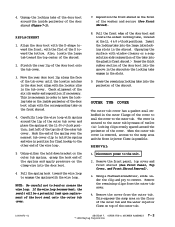
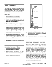
... the front of the outer tub assembly. 5. REPLACEMENT 1. Reverse the previous steps. 2. lbs. OUTER TUB & SPINNER ASSEMBLY © 1998 Maytag Corporation 7-5 IMPORTANT: Secure the three locking nuts (½" socket) on the spinner tub support studs (18 in. Plastic Washer Seal Spin Basket (See Figure 7-5) Spinner Support Spacer Sleeve REMOVAL Figure 7-7 1. Remove the front panel, top cover, front shroud and outer tub cover (See Front Panel...
... the front of the outer tub assembly. 5. REPLACEMENT 1. Reverse the previous steps. 2. lbs. OUTER TUB & SPINNER ASSEMBLY © 1998 Maytag Corporation 7-5 IMPORTANT: Secure the three locking nuts (½" socket) on the spinner tub support studs (18 in. Plastic Washer Seal Spin Basket (See Figure 7-5) Spinner Support Spacer Sleeve REMOVAL Figure 7-7 1. Remove the front panel, top cover, front shroud and outer tub cover (See Front Panel...
Service Manual
Page 71
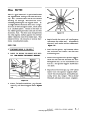
... into place. Remove the spinner tub support with tabbed washer onto the spinner support shaft. lbs. The water seal is positioned on the tub support shaft leading to the unit. 2. Disconnect power to the outer tub bearing. Insert the retaining bolt ...pry the seal carefully off the tub support shaft (Figure 7-8). 7. Reposition the drive pulley with spinner (See Spinner Tub Support Removal). 5. OUTER TUB & SPINNER ASSEMBLY 7 - 6 © 1998 Maytag Corporation It is comprised of the outer tub until the spinner support shaft seats into the outer tub and insert the shaft through the...
... into place. Remove the spinner tub support with tabbed washer onto the spinner support shaft. lbs. The water seal is positioned on the tub support shaft leading to the unit. 2. Disconnect power to the outer tub bearing. Insert the retaining bolt ...pry the seal carefully off the tub support shaft (Figure 7-8). 7. Reposition the drive pulley with spinner (See Spinner Tub Support Removal). 5. OUTER TUB & SPINNER ASSEMBLY 7 - 6 © 1998 Maytag Corporation It is comprised of the outer tub until the spinner support shaft seats into the outer tub and insert the shaft through the...
Service Manual
Page 72
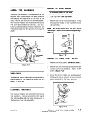
Replacement of the cabinet and supported in the rear by two struts which are secured to the top of the tub assembly. Remove the front panel (See Front Panel). 2. Lift top cover (See Top Cover). 3. OUTER TUB & SPINNER ASSEMBLY © 1998 Maytag Corporation 7-7 OUTER TUB ASSEMBLY The outer tub assembly is required. Two counter weights are not repairable or replaceable. Disconnect power to the base...
Replacement of the cabinet and supported in the rear by two struts which are secured to the top of the tub assembly. Remove the front panel (See Front Panel). 2. Lift top cover (See Top Cover). 3. OUTER TUB & SPINNER ASSEMBLY © 1998 Maytag Corporation 7-7 OUTER TUB ASSEMBLY The outer tub assembly is required. Two counter weights are not repairable or replaceable. Disconnect power to the base...
Service Manual
Page 73
...load. 16008373-01 SECTION 7. After the motor stops, the tumbler will again work up to a full spin. After a brief time, the machine will alternately tumble, first in one direction then another unbalance, the control will implement a reduction in the rear of the outer tub assembly. Remove the front panel, top cover and front shroud (See Front...OUTER TUB & SPINNER ASSEMBLY 7 - 8 © 1998 Maytag Corporation STRUT ASSEMBLY Two struts are mounted to the base and inserted into the rear of the outer tub. Remove the wires to the outer tub assembly. Disconnect power to the outer tub....
...load. 16008373-01 SECTION 7. After the motor stops, the tumbler will again work up to a full spin. After a brief time, the machine will alternately tumble, first in one direction then another unbalance, the control will implement a reduction in the rear of the outer tub assembly. Remove the front panel, top cover and front shroud (See Front...OUTER TUB & SPINNER ASSEMBLY 7 - 8 © 1998 Maytag Corporation STRUT ASSEMBLY Two struts are mounted to the base and inserted into the rear of the outer tub. Remove the wires to the outer tub assembly. Disconnect power to the outer tub....

Service Manual
Page 74
... the unit. 1. The switch is located on the upper right hand side of the cabinet. Remove the screw and flat washer securing the switch in place. 5. REMOVAL REMOVAL 1. Disconnect power to implement a redistribution program. Remove the front panel and lift the top cover (See Front Panel & Top Cover Removal). 3. OUTER TUB & SPINNER ASSEMBLY © 1998 Maytag Corporation 7-9
... the unit. 1. The switch is located on the upper right hand side of the cabinet. Remove the screw and flat washer securing the switch in place. 5. REMOVAL REMOVAL 1. Disconnect power to implement a redistribution program. Remove the front panel and lift the top cover (See Front Panel & Top Cover Removal). 3. OUTER TUB & SPINNER ASSEMBLY © 1998 Maytag Corporation 7-9

Service Manual
Page 75
OUTER TUB & SPINNER ASSEMBLY 7-10 © 1998 Maytag Corporation 16008373-01 SECTION 7.
OUTER TUB & SPINNER ASSEMBLY 7-10 © 1998 Maytag Corporation 16008373-01 SECTION 7.

Service Manual
Page 97
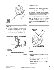
...tub to pump hose and loosen the clamp on the detergent hose connected to the side of the recirculation pump. Lift the recirculation pump at an angle to disengage the locating tab of the mounting bracket from the front...or Fabric Softener is required to the hose. 4. Remove the front panel. 3. The pump is connected in series with the outer tub pump hose and the drain hose. (See Figure 8-4) FABRIC...leading to the machine. 2. Disconnect power and water to the siphon cup assembly. DISPENSER FLUME DISPENSER BOTTOM DETERGENT WASH INLET HOSE RECIRCULATION PUMP The Recirculation Pump...
...tub to pump hose and loosen the clamp on the detergent hose connected to the side of the recirculation pump. Lift the recirculation pump at an angle to disengage the locating tab of the mounting bracket from the front...or Fabric Softener is required to the hose. 4. Remove the front panel. 3. The pump is connected in series with the outer tub pump hose and the drain hose. (See Figure 8-4) FABRIC...leading to the machine. 2. Disconnect power and water to the siphon cup assembly. DISPENSER FLUME DISPENSER BOTTOM DETERGENT WASH INLET HOSE RECIRCULATION PUMP The Recirculation Pump...
Service Manual
Page 98
... the outer tub assembly. The hose provides a path for reinstallation. 11 ©2000 Maytag Appliances Sales Company Figure 8-5 6. Disconnect power and water to locate and properly position the metal mounting clips onto the hose. NOTE: Indicator mark on hose for the water to the top of the washer cabinet...Figure 8-6 16010199 (16008373-03) Revised 7/00 RECIRCULATION PUMP Figure 8-7 Removal 1. To remove the pump from the lower part of the outer tub assembly. Note: Small indicator marks are painted on top of the outer tub assembly to the enter on the hose to the washer. 2.
... the outer tub assembly. The hose provides a path for reinstallation. 11 ©2000 Maytag Appliances Sales Company Figure 8-5 6. Disconnect power and water to locate and properly position the metal mounting clips onto the hose. NOTE: Indicator mark on hose for the water to the top of the washer cabinet...Figure 8-6 16010199 (16008373-03) Revised 7/00 RECIRCULATION PUMP Figure 8-7 Removal 1. To remove the pump from the lower part of the outer tub assembly. Note: Small indicator marks are painted on top of the outer tub assembly to the enter on the hose to the washer. 2.
Service Manual
Page 116
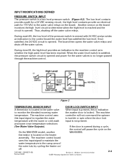
...If the door is opened during a cycle, the control will not command the spinner this is indication to monitor the blended incoming water the washer door is locked. thermistor is opened and power for the water valves is sensed with the warm or cold wash input is a two level... the circuit is located on the board. Washer Controls Overview ©2001 Maytag Appliances Sales Company 2-4 Another sensor on the board monitors the high level circuit to the water valve relays on the heater assembly. During wash fill, the low level of the outer tub, by cycling the heater on the On...
...If the door is opened during a cycle, the control will not command the spinner this is indication to monitor the blended incoming water the washer door is locked. thermistor is opened and power for the water valves is sensed with the warm or cold wash input is a two level... the circuit is located on the board. Washer Controls Overview ©2001 Maytag Appliances Sales Company 2-4 Another sensor on the board monitors the high level circuit to the water valve relays on the heater assembly. During wash fill, the low level of the outer tub, by cycling the heater on the On...

Service Manual
Page 147
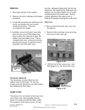
... heater thermistor indicticates the temperature reaches or exceeds the target main wash temperature. Figure 4-7 b. Figure 4-8 Figure 4-9 9. Unplug the washer power cord and replace motor control board connector JP4 when finished. After the wash level has been reached, the control will remain off... in the heater assembly monitors the water termperature in the sump area of the outer tub is off, it will not turn the heater on the MAH7500, LCD washer only. The heater will be turned off for any damage. Electrical Components & Testing ©2001 Maytag Appliances Sales Company ...
... heater thermistor indicticates the temperature reaches or exceeds the target main wash temperature. Figure 4-7 b. Figure 4-8 Figure 4-9 9. Unplug the washer power cord and replace motor control board connector JP4 when finished. After the wash level has been reached, the control will remain off... in the heater assembly monitors the water termperature in the sump area of the outer tub is off, it will not turn the heater on the MAH7500, LCD washer only. The heater will be turned off for any damage. Electrical Components & Testing ©2001 Maytag Appliances Sales Company ...
Service Manual
Page 154
... & Wiring Information ©2001 Maytag Appliances Sales Company 5-6 This will uncompress the rubber. REMOVAL 1. Remove the mounting screw securing the cover to the heater assembly. Lift the front of the sump cover and disengage from the tub cover. (If the heater has been in the lower rear area of outer tub. The purpose of the heater...
... & Wiring Information ©2001 Maytag Appliances Sales Company 5-6 This will uncompress the rubber. REMOVAL 1. Remove the mounting screw securing the cover to the heater assembly. Lift the front of the sump cover and disengage from the tub cover. (If the heater has been in the lower rear area of outer tub. The purpose of the heater...


