
Service Manual
Page 5
... ...5-3 DOOR LOCK MECHANISM ...5-3 FRONT SHROUD ASSEMBLY ...5-4 CABINET ASSEMBLY W/REAR ACCESS PANEL 5-5 SECTION 6. OUTER TUB & SPINNER ASSEMBLY 7 - 1 B A F F L E S ...7 - 1 DOOR BOOT ...7 - 1 OUTER TUB COVER ...7-2 SPIN BASKET ASSEMBLY W/BALANCE RING 7-3 DRIVE PULLEY ...7-4 SPINNER TUB SUPPORT ...7-5 16008373-01 ©1997 Maytag Corporation CONTENTS iii T R O U B L E S H O O T I O N 3 . S E C T I N G ...3 - 1 DIAGNOSTIC FLOW CHARTS...3-4 Fills and Will Not Tumble ...3-4 Washer Overfills ...3-5 Washer Will Not Spin ...3-6 Machine...
... ...5-3 DOOR LOCK MECHANISM ...5-3 FRONT SHROUD ASSEMBLY ...5-4 CABINET ASSEMBLY W/REAR ACCESS PANEL 5-5 SECTION 6. OUTER TUB & SPINNER ASSEMBLY 7 - 1 B A F F L E S ...7 - 1 DOOR BOOT ...7 - 1 OUTER TUB COVER ...7-2 SPIN BASKET ASSEMBLY W/BALANCE RING 7-3 DRIVE PULLEY ...7-4 SPINNER TUB SUPPORT ...7-5 16008373-01 ©1997 Maytag Corporation CONTENTS iii T R O U B L E S H O O T I O N 3 . S E C T I N G ...3 - 1 DIAGNOSTIC FLOW CHARTS...3-4 Fills and Will Not Tumble ...3-4 Washer Overfills ...3-5 Washer Will Not Spin ...3-6 Machine...
Service Manual
Page 7
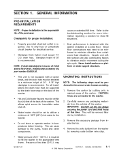
...are connected to a minimum height of 5 feet above floor level, install pump accessory kit, part number 22002136. • This unit is recommended. Remove the crate bottom from unbalanced load situations. This allows quick access for electrical service. • Standpipe Drain...INSTRUCTIONS NOTE: The following steps must be set to fill the washer in marked areas of less than 20 P.S.I . GENERAL INFORMATION 1-1 Wood floor constructions may 16008373-01 © 1998 Maytag Corporation SECTION 1. GENERAL INFORMATION PRE-INSTALLATION REQUIREMENTS NOTE: Proper installation...
...are connected to a minimum height of 5 feet above floor level, install pump accessory kit, part number 22002136. • This unit is recommended. Remove the crate bottom from unbalanced load situations. This allows quick access for electrical service. • Standpipe Drain...INSTRUCTIONS NOTE: The following steps must be set to fill the washer in marked areas of less than 20 P.S.I . GENERAL INFORMATION 1-1 Wood floor constructions may 16008373-01 © 1998 Maytag Corporation SECTION 1. GENERAL INFORMATION PRE-INSTALLATION REQUIREMENTS NOTE: Proper installation...
Service Manual
Page 10
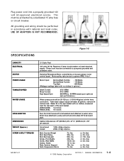
Motor pulley ratio (motor to spinner RPM ) 14 to pump and w ill accomm odate 36" dr ain stand p i p e.... lbs. 30in. lbs 90in. lbs 18.5in. lbs 18in. Cabinet dimensions: 27" (68.58cm) W x 27 ½" (69.85cm) D x 36" (91.44cm )H . lbs) © 1998 Maytag Corporation SECTION 1. This must be performed in . Requir es 15 amp circuit br...; 3in. lbs) (± 3in. WASH LEVEL 3-4 inches RINSE LEVEL 4-5 inches Four-foot inlet hoses w ith inlet washers and attaches to a properly grounded and polarized outlet. lbs) (± 3in. USE OF ADAPTERS IS NOT RECOMMENDED. Power cord...
Motor pulley ratio (motor to spinner RPM ) 14 to pump and w ill accomm odate 36" dr ain stand p i p e.... lbs. 30in. lbs 90in. lbs 18.5in. lbs 18in. Cabinet dimensions: 27" (68.58cm) W x 27 ½" (69.85cm) D x 36" (91.44cm )H . lbs) © 1998 Maytag Corporation SECTION 1. This must be performed in . Requir es 15 amp circuit br...; 3in. lbs) (± 3in. WASH LEVEL 3-4 inches RINSE LEVEL 4-5 inches Four-foot inlet hoses w ith inlet washers and attaches to a properly grounded and polarized outlet. lbs) (± 3in. USE OF ADAPTERS IS NOT RECOMMENDED. Power cord...
Service Manual
Page 11
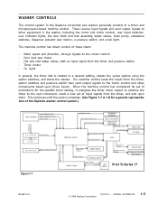
...pump, unbalance switches, dispenser actuator wax motors, a pressure switch, and a tub light. Timer motor. - The machine control reads the inputs from the timer, option switches and pressure switch then send output signals to the motor control and other equipment in the Neptune horizontal axis washer generally consists of the Neptune washer... control system.) Figure 1-7 16008373-01 Prior To Series 17 © 1998 Maytag Corporation SECTION 1. This continues until the cycle...
...pump, unbalance switches, dispenser actuator wax motors, a pressure switch, and a tub light. Timer motor. - The machine control reads the inputs from the timer, option switches and pressure switch then send output signals to the motor control and other equipment in the Neptune horizontal axis washer generally consists of the Neptune washer... control system.) Figure 1-7 16008373-01 Prior To Series 17 © 1998 Maytag Corporation SECTION 1. This continues until the cycle...
Service Manual
Page 23
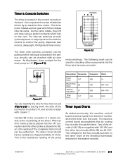
...to the neutral leg of the connector to contact 14, and across to control the pump, dispenser wax motors, delay light, ON light and timer motor. The voltages for the... COMPONENTS & TESTING 2 - 3 © 1998 Maytag Corporation The machine control board accomplishes this by an electric timer motor. It is composed of a series of the electrical schematic enclosed in the control console ... complete drain circuit can be performed. Timer & Console Switches The timer is located in the washer console. 16008373-01 SECTION 2. The following chart can be used for checking other two circuits ...
...to the neutral leg of the connector to contact 14, and across to control the pump, dispenser wax motors, delay light, ON light and timer motor. The voltages for the... COMPONENTS & TESTING 2 - 3 © 1998 Maytag Corporation The machine control board accomplishes this by an electric timer motor. It is composed of a series of the electrical schematic enclosed in the control console ... complete drain circuit can be performed. Timer & Console Switches The timer is located in the washer console. 16008373-01 SECTION 2. The following chart can be used for checking other two circuits ...
Service Manual
Page 62
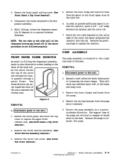
...clamp and injector hose from the spout on the side wall of the base. FRONT WATER FLUME INJECTOR As water is filling the dispenser assembly, water is mounted to saturate the clothes load. As the water enters the top of the tub to the right rear ...© 1998 Maytag Corporation Figure 6-5 REMOVAL 1. Disconnect power to loosening the hose clamps. Pinch the two tabs exposed on the outer edge of the outer tub. 6. This will catch any residual water left in the base. Remove the wiring harness from the pump. 4. Remove the front shroud assembly (See Front Shroud Assembly Removal...
...clamp and injector hose from the spout on the side wall of the base. FRONT WATER FLUME INJECTOR As water is filling the dispenser assembly, water is mounted to saturate the clothes load. As the water enters the top of the tub to the right rear ...© 1998 Maytag Corporation Figure 6-5 REMOVAL 1. Disconnect power to loosening the hose clamps. Pinch the two tabs exposed on the outer edge of the outer tub. 6. This will catch any residual water left in the base. Remove the wiring harness from the pump. 4. Remove the front shroud assembly (See Front Shroud Assembly Removal...
Service Manual
Page 63
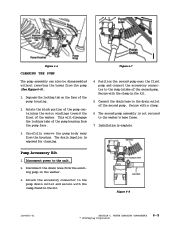
...pump containing the motor windings toward the front of the pump housing. 2. Carefully remove the pump body away from the pump (See Figure 6-6). 1. The drain impeller is not secured to the washer's base frame. 7. Disconnect the drain hose from the pump face. 4. Position the second pump near the first pump.... 3. Depress the locking tab on the face of the washer. Secure with the clamp in the washer. 3. WATER CARRYING COMPONENTS © 1998 Maytag Corporation 6-5 Figure 6-6 CLEANING THE PUMP Figure 6-7 The pump assembly can also be disassembled without removing the hoses from the...
...pump containing the motor windings toward the front of the pump housing. 2. Carefully remove the pump body away from the pump (See Figure 6-6). 1. The drain impeller is not secured to the washer's base frame. 7. Disconnect the drain hose from the pump face. 4. Position the second pump near the first pump.... 3. Depress the locking tab on the face of the washer. Secure with the clamp in the washer. 3. WATER CARRYING COMPONENTS © 1998 Maytag Corporation 6-5 Figure 6-6 CLEANING THE PUMP Figure 6-7 The pump assembly can also be disassembled without removing the hoses from the...

Service Manual
Page 64
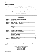
...shield. Disconnect power to the rear wall of the cabinet. Reverse the previous steps for replacement. REMOVAL 1. WATER CARRYING COMPONENTS 6-6 © 1998 Maytag Corporation Remove the four ¼" hex head screws securing the access panel to the unit. 2. With access into the machine compartment, spread a ...towel under the connection of the drain hose to the pump and is protected externally by a shield. Loosen the clamp and remove the drain hose (Figure 6-10). 5. The drain hose is routed ...
...shield. Disconnect power to the rear wall of the cabinet. Reverse the previous steps for replacement. REMOVAL 1. WATER CARRYING COMPONENTS 6-6 © 1998 Maytag Corporation Remove the four ¼" hex head screws securing the access panel to the unit. 2. With access into the machine compartment, spread a ...towel under the connection of the drain hose to the pump and is protected externally by a shield. Loosen the clamp and remove the drain hose (Figure 6-10). 5. The drain hose is routed ...
Service Manual
Page 88
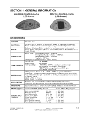
... COMPONENTS 9 WATER VALVE 9 DISPENSER ASSEMBLY 9 RECIRCULATION PUMP 10 DETERGENT HOSE 11 SECTION 9. WIRING INFORMATION 14 For additional information on material covered in this manual, including safety issues, contact: Maytag Appliances Sales Company 240 Edwards Street, S.E. Models covered...: 423-472-3333 16010199 (16008373-03) 1 Revised 7/00 ©2000 Maytag Appliances Sales Company BASIC MACHINE OPERATION 3 SECTION 4. WASHER CONTROLS OVERVIEW 3 SECTION 5. EXPLODED VIEW 7 SECTION 7. This Maytag Washer Service Manual supplement covers Models MAH4000 & MAH5500A.
... COMPONENTS 9 WATER VALVE 9 DISPENSER ASSEMBLY 9 RECIRCULATION PUMP 10 DETERGENT HOSE 11 SECTION 9. WIRING INFORMATION 14 For additional information on material covered in this manual, including safety issues, contact: Maytag Appliances Sales Company 240 Edwards Street, S.E. Models covered...: 423-472-3333 16010199 (16008373-03) 1 Revised 7/00 ©2000 Maytag Appliances Sales Company BASIC MACHINE OPERATION 3 SECTION 4. WASHER CONTROLS OVERVIEW 3 SECTION 5. EXPLODED VIEW 7 SECTION 7. This Maytag Washer Service Manual supplement covers Models MAH4000 & MAH5500A.
Service Manual
Page 89
...control board. Total water usage is supplemental to water valve. Cabinet Dimensions: 27" (68.58cm) W x 271/2" (69.85cm) D x 36...lbs.) (+ 3 in . lbs.) 16010199 (16008373-03) 2 Revised 7/00 ©2000 Maytag Appliances Sales Company MAH4000/MAH5500A CONTROL FACIA SECTION 2. Drain hose attached to 1. lbs. 90 ...pump and will accommodate 36" drain stand pipe. lbs.) (+ 3 in . (The following information is approximately 25 gallons, varies with clothes load..., Counter Weight Bolt, Spin Pulley Bolt, Belt Adjuster Screw, Front Baffle Screw, Rear Baffle Clamp, Hoses Nuts, Spinner Support Nuts...
...control board. Total water usage is supplemental to water valve. Cabinet Dimensions: 27" (68.58cm) W x 271/2" (69.85cm) D x 36...lbs.) (+ 3 in . lbs.) 16010199 (16008373-03) 2 Revised 7/00 ©2000 Maytag Appliances Sales Company MAH4000/MAH5500A CONTROL FACIA SECTION 2. Drain hose attached to 1. lbs. 90 ...pump and will accommodate 36" drain stand pipe. lbs.) (+ 3 in . (The following information is approximately 25 gallons, varies with clothes load..., Counter Weight Bolt, Spin Pulley Bolt, Belt Adjuster Screw, Front Baffle Screw, Rear Baffle Clamp, Hoses Nuts, Spinner Support Nuts...
Service Manual
Page 90
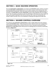
.... WASHER CONTROLS OVERVIEW The software of detergent throughout the wash load. Fabric Selections on the MAH4000 and all the MAH5500A), power is able to be directly controlled by the timer. (Figure 4-1) Figure 4-1 Series 10 (MAH4000 only) Figure 4-2 16010199 (16008373-03) Revised 7/00 Series 11 & Later (MAH4000 & MAH5500A) 3 ©2000 Maytag Appliances Sales Company The recirculation pump...
.... WASHER CONTROLS OVERVIEW The software of detergent throughout the wash load. Fabric Selections on the MAH4000 and all the MAH5500A), power is able to be directly controlled by the timer. (Figure 4-1) Figure 4-1 Series 10 (MAH4000 only) Figure 4-2 16010199 (16008373-03) Revised 7/00 Series 11 & Later (MAH4000 & MAH5500A) 3 ©2000 Maytag Appliances Sales Company The recirculation pump...
Service Manual
Page 91
...5-1 Cycles on the Fabrics switch now list the cycles according to starting the recirculation pump. This simiplifies how to select the cycles in the following pages. This was done to force the washer to fill with water prior to how clothes are sorted. SECTION 5. A new ...connector and the pump is controlled through the pressure switch (Figure 4-2). At series 11 the timer was changed, wire harness revised and the schematic was changed in series with longer tumble times during the rinse. (See Figure 5-1) 16010199 (16008373-03) 4 Revised 7/00 ©2000 Maytag Appliances Sales ...
...5-1 Cycles on the Fabrics switch now list the cycles according to starting the recirculation pump. This simiplifies how to select the cycles in the following pages. This was done to force the washer to fill with water prior to how clothes are sorted. SECTION 5. A new ...connector and the pump is controlled through the pressure switch (Figure 4-2). At series 11 the timer was changed, wire harness revised and the schematic was changed in series with longer tumble times during the rinse. (See Figure 5-1) 16010199 (16008373-03) 4 Revised 7/00 ©2000 Maytag Appliances Sales ...

Service Manual
Page 97
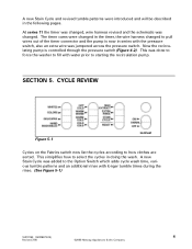
... channels leading to disengage the locating tab of the mounting bracket from the front or the rear of the machine. DISPENSER BOTTOM (TOP VIEW) 5. The pump is connected in series with the outer tub pump hose and the drain hose. (See Figure 8-4) FABRIC SOFTENER INLET HOSE ... same as the previously used wax motor. DISPENSER FLUME DISPENSER BOTTOM DETERGENT WASH INLET HOSE RECIRCULATION PUMP The Recirculation Pump is accessible from the baseframe. (See Figure 8-5) Figure 8-3 NOZZLE WAS REMOVED 16010199 (16008373-03) 10 Revised 7/00 ©2000 Maytag Appliances Sales Company
... channels leading to disengage the locating tab of the mounting bracket from the front or the rear of the machine. DISPENSER BOTTOM (TOP VIEW) 5. The pump is connected in series with the outer tub pump hose and the drain hose. (See Figure 8-4) FABRIC SOFTENER INLET HOSE ... same as the previously used wax motor. DISPENSER FLUME DISPENSER BOTTOM DETERGENT WASH INLET HOSE RECIRCULATION PUMP The Recirculation Pump is accessible from the baseframe. (See Figure 8-5) Figure 8-3 NOZZLE WAS REMOVED 16010199 (16008373-03) 10 Revised 7/00 ©2000 Maytag Appliances Sales Company
Service Manual
Page 98
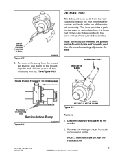
...the enter on the hose to the top of the outer tub assembly. Remove the detergent hose from the recirculation pump up the rear of the washer cabinet and leads to locate and properly position the metal mounting clips onto the hose. Figure 8-5 6. Disconnect ...power and water to recirculate from the mounting bracket, pull down on hose for reinstallation. 11 ©2000 Maytag Appliances Sales Company NOTE: Indicator mark on the mounting tabs and slide the pump...
...the enter on the hose to the top of the outer tub assembly. Remove the detergent hose from the recirculation pump up the rear of the washer cabinet and leads to locate and properly position the metal mounting clips onto the hose. Figure 8-5 6. Disconnect ...power and water to recirculate from the mounting bracket, pull down on hose for reinstallation. 11 ©2000 Maytag Appliances Sales Company NOTE: Indicator mark on the mounting tabs and slide the pump...

Service Manual
Page 100
Figure 8-12 7. To reinstall, reverse the removal steps taking note of the outer tub with the detergent hose. 8. NOTE: The upper wire harness for the unbalance circuit is secured to the mounting clips, making sure the hose does not kink above the recirculation pump. 16010199 (16008373-03) 13 Revised 7/00 ©2000 Maytag Appliances Sales Company Loosen the clamp on the detergent hose on the hose in reference to the top of the indicators on the outer tub and remove the hose. 9. The saddle horn is snapped into the saddle horn with a screw.
Figure 8-12 7. To reinstall, reverse the removal steps taking note of the outer tub with the detergent hose. 8. NOTE: The upper wire harness for the unbalance circuit is secured to the mounting clips, making sure the hose does not kink above the recirculation pump. 16010199 (16008373-03) 13 Revised 7/00 ©2000 Maytag Appliances Sales Company Loosen the clamp on the detergent hose on the hose in reference to the top of the indicators on the outer tub and remove the hose. 9. The saddle horn is snapped into the saddle horn with a screw.
Service Manual
Page 109
...Front Baffle Screw, Rear Baffle Clamp, Hoses Nuts, Spinner Support Nuts, Suspension struts 7 ft. Crated 187lb. (85kg.) Approx. (+ 3 ft. lbs.) (+ 3 ft. General Information ©2001 Maytag...Washer (MAH5500B) 1000 RPM No tuning of the spin basket WASH LEVEL 2-3 inches RINSE LEVEL 3-5 inches Four foot inlet hoses with inlet washers and attached to pump...rpm. lbs. 18.5 in the spin basket with clothes load. lbs.) (+ 3 ft. GENERAL INFORMATION MAH5500B CONTROL ...HOSE LENGTHS DIMENSIONS 3.1 Cubic Feet 120 Volts, 60 Hz; Cabinet Dimensions: 27" (68.58cm) W x 271/2" (69.85cm) D x 36"...
...Front Baffle Screw, Rear Baffle Clamp, Hoses Nuts, Spinner Support Nuts, Suspension struts 7 ft. Crated 187lb. (85kg.) Approx. (+ 3 ft. lbs.) (+ 3 ft. General Information ©2001 Maytag...Washer (MAH5500B) 1000 RPM No tuning of the spin basket WASH LEVEL 2-3 inches RINSE LEVEL 3-5 inches Four foot inlet hoses with inlet washers and attached to pump...rpm. lbs. 18.5 in the spin basket with clothes load. lbs.) (+ 3 ft. GENERAL INFORMATION MAH5500B CONTROL ...HOSE LENGTHS DIMENSIONS 3.1 Cubic Feet 120 Volts, 60 Hz; Cabinet Dimensions: 27" (68.58cm) W x 271/2" (69.85cm) D x 36"...
Service Manual
Page 110
... sump cap is placed directly above the sump area which modify the main wash. The door lock mechanism was changed to the MAH4000 washer, with the exception being they do not have recirculation of the detergent and the wash water. The motor drive system was updated from... off. Filling and draining will be dependent on user selections. General Information ©2001 Maytag Appliances Sales Company 1-2 The stain cycle option also adds rinse time to the sump area of the pump, thus eliminating the airdome hose. Note: No permanent locking, tumbling, or spinning shall...
... sump cap is placed directly above the sump area which modify the main wash. The door lock mechanism was changed to the MAH4000 washer, with the exception being they do not have recirculation of the detergent and the wash water. The motor drive system was updated from... off. Filling and draining will be dependent on user selections. General Information ©2001 Maytag Appliances Sales Company 1-2 The stain cycle option also adds rinse time to the sump area of the pump, thus eliminating the airdome hose. Note: No permanent locking, tumbling, or spinning shall...

Service Manual
Page 112
... RPM and then on and 45 seconds off the machine has reached the target duty cycle. The water temperature entering the washer during rinse is not allowed with stain) H/C, W/C, and C/C AND W/W Rinse Stain Cycle Rinse water temperature N N Non-tempered cold. ...Pump a) =540 rpm and 30 seconds after 15 second on until next step in the cycle 16010486 (16008373-05) Revised 02/01 Section 1. e) Coast down during all other spins On continuous until the machine reaches 0 RPM. The following table shows the temperature based on the user selections. General Information ©2001 Maytag...
... RPM and then on and 45 seconds off the machine has reached the target duty cycle. The water temperature entering the washer during rinse is not allowed with stain) H/C, W/C, and C/C AND W/W Rinse Stain Cycle Rinse water temperature N N Non-tempered cold. ...Pump a) =540 rpm and 30 seconds after 15 second on until next step in the cycle 16010486 (16008373-05) Revised 02/01 Section 1. e) Coast down during all other spins On continuous until the machine reaches 0 RPM. The following table shows the temperature based on the user selections. General Information ©2001 Maytag...
Service Manual
Page 125
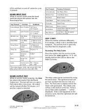
...time. The up /down arrow will display and turn on above the Stain Cycle key. The oldest code will be displayed. Washer Controls Overview ©2001 Maytag Appliances Sales Company 2-13 Max extract LED and extra rinse LED=200. The severity level is generally less than that of ... Function Performed Hot Water Valve Cold Water Valve Bleach Valve Fabric Softener Valve Drain Pump Motor Control Unlock Door (Sends a pulse every 2 seconds) Lock Door (Sends a pulse every 2 seconds) HELP CODES When the washer performs differently from design, a Help code is selected. or if another output ...
...time. The up /down arrow will display and turn on above the Stain Cycle key. The oldest code will be displayed. Washer Controls Overview ©2001 Maytag Appliances Sales Company 2-13 Max extract LED and extra rinse LED=200. The severity level is generally less than that of ... Function Performed Hot Water Valve Cold Water Valve Bleach Valve Fabric Softener Valve Drain Pump Motor Control Unlock Door (Sends a pulse every 2 seconds) Lock Door (Sends a pulse every 2 seconds) HELP CODES When the washer performs differently from design, a Help code is selected. or if another output ...
Service Manual
Page 131
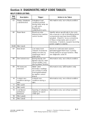
... being demanded by machine control board. Check for proper function. Check pump for restricted drain system, kinked/plugged drain hose or pump. May see diagnostic code 01. Informative only; (LED washer only) Informative only; non-critical condition Identify where specifically in the cycle... this occurred, to be Taken Unbalance load condition existed during a spin. Check for loose...
... being demanded by machine control board. Check for proper function. Check pump for restricted drain system, kinked/plugged drain hose or pump. May see diagnostic code 01. Informative only; (LED washer only) Informative only; non-critical condition Identify where specifically in the cycle... this occurred, to be Taken Unbalance load condition existed during a spin. Check for loose...


