
Use and Care Guide
Page 9
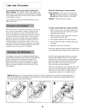
...-compartment container is removed from the washer before doing a load of laundry. 1 2 3 OFTENER BLEACH FILL AX M S M AX FILL 8 Do not spray cleaners directly on the washer or washload. We recommend taking the following as shown in illustration #1. Run the washer through your washer interior. It is clean, follow ... happen, set the washer for the bleach and softener. For easy clean-up of the dispenser, grasp the removable two-compartment container (for cleaning substances to drain into the tub. Use a soft cloth to wipe up . Do not use of cold water. Wipe the ...
...-compartment container is removed from the washer before doing a load of laundry. 1 2 3 OFTENER BLEACH FILL AX M S M AX FILL 8 Do not spray cleaners directly on the washer or washload. We recommend taking the following as shown in illustration #1. Run the washer through your washer interior. It is clean, follow ... happen, set the washer for the bleach and softener. For easy clean-up of the dispenser, grasp the removable two-compartment container (for cleaning substances to drain into the tub. Use a soft cloth to wipe up . Do not use of cold water. Wipe the ...
Use and Care Guide
Page 11
... be a pause or soak period in the cycle. Won't Spin or Drain • Check fuse or reset circuit breaker. • Straighten drain hoses. BEFORE YOU CALL CHECK THESE POINTS IF YOUR MAYTAG® NEPTUNE® WASHER... Leaks Water • Make sure door is firmly closed . •...Load is closed . • Make sure hose connections are selected. If there is Completely Full of Suds • Run the clothes washer through the dispenser when cold or warm wash temperatures are tight. • Make sure end of the water. Tub is a drain restriction, call for front load washers...
... be a pause or soak period in the cycle. Won't Spin or Drain • Check fuse or reset circuit breaker. • Straighten drain hoses. BEFORE YOU CALL CHECK THESE POINTS IF YOUR MAYTAG® NEPTUNE® WASHER... Leaks Water • Make sure door is firmly closed . •...Load is closed . • Make sure hose connections are selected. If there is Completely Full of Suds • Run the clothes washer through the dispenser when cold or warm wash temperatures are tight. • Make sure end of the water. Tub is a drain restriction, call for front load washers...
Use and Care Guide
Page 13
... back in . The door must be displayed to unlock the door but has been unsuccessful. Code Symbol Meaning Solution The washer detects that specific load. The washer door must be opened . For any codes not listed above, call 1-800-688-2080. 12 Close the door tightly... difficulty draining. Make sure door is a safety feature. Call for that the door is open all the way. The washer experienced a power failure. This is tightly closed. Reduce the amount of detergent used for service. Check for deaf, hearing impaired or speech impaired, call Maytag Customer ...
... back in . The door must be displayed to unlock the door but has been unsuccessful. Code Symbol Meaning Solution The washer detects that specific load. The washer door must be opened . For any codes not listed above, call 1-800-688-2080. 12 Close the door tightly... difficulty draining. Make sure door is a safety feature. Call for that the door is open all the way. The washer experienced a power failure. This is tightly closed. Reduce the amount of detergent used for service. Check for deaf, hearing impaired or speech impaired, call Maytag Customer ...
Use and Care Guide
Page 14
...speed. Detergent is designed to make a series of the cycle. Sloshing or gurgling water sound when washer is off and the tub is needed. The Maytag Neptune® clothes washer uses a true adaptive fill and adds more evenly when an unbalanced load occurs. Water is filling. The tub... is started. Clothes washer maintains a slightly reduced spin speed after the washer has been tumbling for maximum performance. Clicking/draining sounds when washer is dispensed during the wash cycle as it sounds like an out-of wash. The tumbler will make the washer spin smoothly. Fabric ...
...speed. Detergent is designed to make a series of the cycle. Sloshing or gurgling water sound when washer is off and the tub is needed. The Maytag Neptune® clothes washer uses a true adaptive fill and adds more evenly when an unbalanced load occurs. Water is filling. The tub... is started. Clothes washer maintains a slightly reduced spin speed after the washer has been tumbling for maximum performance. Clicking/draining sounds when washer is dispensed during the wash cycle as it sounds like an out-of wash. The tumbler will make the washer spin smoothly. Fabric ...
Service Manual
Page 5
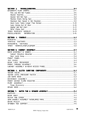
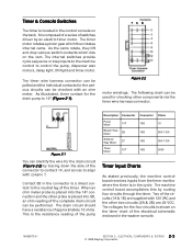
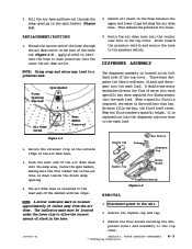
...-01 ©1997 Maytag Corporation CONTENTS iii WATER CARRYING COMPONENTS 6 - 1 WATER VALVE...6 - 1 WATER LEVEL PRESSURE SWITCH...6-2 AIR DOME HOSE ...6-2 DISPENSER ASSEMBLY ...6-3 FRONT WATER FLUME INJECTOR...6-4 PUMP ASSEMBLY ...6-4 Pump Accessory ...6-5 DRAIN HOSE ...6-6 SECTION 7. CONSOLE ...4 - 1 R E M O V A L ...4-1 VERTICAL SWITCHES...4-2 HORIZONTAL SWITCHES ...4-2 TIMER REMOVAL/REPLACEMENT...4-3 SECTION 5. S E C T I N G ...3 - 1 DIAGNOSTIC FLOW CHARTS...3-4 Fills and Will Not Tumble ...3-4 Washer Overfills ...3-5 Washer Will Not Spin...
...-01 ©1997 Maytag Corporation CONTENTS iii WATER CARRYING COMPONENTS 6 - 1 WATER VALVE...6 - 1 WATER LEVEL PRESSURE SWITCH...6-2 AIR DOME HOSE ...6-2 DISPENSER ASSEMBLY ...6-3 FRONT WATER FLUME INJECTOR...6-4 PUMP ASSEMBLY ...6-4 Pump Accessory ...6-5 DRAIN HOSE ...6-6 SECTION 7. CONSOLE ...4 - 1 R E M O V A L ...4-1 VERTICAL SWITCHES...4-2 HORIZONTAL SWITCHES ...4-2 TIMER REMOVAL/REPLACEMENT...4-3 SECTION 5. S E C T I N G ...3 - 1 DIAGNOSTIC FLOW CHARTS...3-4 Fills and Will Not Tumble ...3-4 Washer Overfills ...3-5 Washer Will Not Spin...
Service Manual
Page 7
...Maytag Corporation SECTION 1. Carefully remove any packaging materials from the washer by removing crate bottom wire clips. • Water pressure of the washer...drain standpipe is required to the washer. • Do not store or operate washer in excess of the washer...washer in marked areas of 24". This allows quick access for electrical service. • Standpipe Drain System must be within four (4) feet of the back of the washer.... Refer to minimize vibration from inside the tub. 4. Never install washer...drain...washer ...
...Maytag Corporation SECTION 1. Carefully remove any packaging materials from the washer by removing crate bottom wire clips. • Water pressure of the washer...drain standpipe is required to the washer. • Do not store or operate washer in excess of the washer...washer in marked areas of 24". This allows quick access for electrical service. • Standpipe Drain System must be within four (4) feet of the back of the washer.... Refer to minimize vibration from inside the tub. 4. Never install washer...drain...washer ...
Service Manual
Page 9
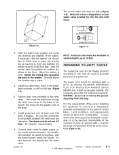
... grounded and polarized three (3) prong receptacle (Figure 1-6). 16008373-01 © 1998 Maytag Corporation SECTION 1. Install gooseneck end of drain hose into position and check the levelness and stability of the washer. CAUTION: Do not cut or remove the grounding prong from this plug. GENERAL ...must be taken into the plastic hook of installation. Slide the washer into drain standpipe. Attach hoses to the floor. Connect inlet hoses to level and stabilize the washer securely on all Maytag products operating on the back of the person installing the appliance...
... grounded and polarized three (3) prong receptacle (Figure 1-6). 16008373-01 © 1998 Maytag Corporation SECTION 1. Install gooseneck end of drain hose into position and check the levelness and stability of the washer. CAUTION: Do not cut or remove the grounding prong from this plug. GENERAL ...must be taken into the plastic hook of installation. Slide the washer into drain standpipe. Attach hoses to the floor. Connect inlet hoses to level and stabilize the washer securely on all Maytag products operating on the back of the person installing the appliance...
Service Manual
Page 11
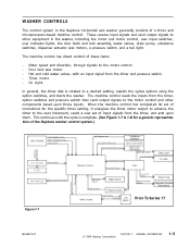
... The control system in the washer, including the motor and motor control, user input switches, user indicator lights, the door latch and lock assembly, water valves, drain pump, unbalance switches, dispenser actuator wax motors, a pressure switch, and a tub light. Hot and cold water valves,... and pressure switch then send output signals to the next increment, reads a new set of the Neptune washer control system.) Figure 1-7 16008373-01 Prior To Series 17 © 1998 Maytag Corporation SECTION 1. These receive input signals and send output signals to the motor control. - The machine...
... The control system in the washer, including the motor and motor control, user input switches, user indicator lights, the door latch and lock assembly, water valves, drain pump, unbalance switches, dispenser actuator wax motors, a pressure switch, and a tub light. Hot and cold water valves,... and pressure switch then send output signals to the next increment, reads a new set of the Neptune washer control system.) Figure 1-7 16008373-01 Prior To Series 17 © 1998 Maytag Corporation SECTION 1. These receive input signals and send output signals to the motor control. - The machine...
Service Manual
Page 13
..., first rinse, second rinse, and extra rinse increments, the wash side circuit in the water valve to measure how quickly the washer is draining. machine control interprets this loss of power as defined by the timer and user input switches (See Push-To-Start/Line Relay ...relay and begin the sequence timing defined for each fill (See Water Valve Outputs). 16008373-01 © 1998 Maytag Corporation SECTION 1. GENERAL INFORMATION 1-7 When the water level drains below the wash full level, the circuit will energize the timer motor output to regulate the water temperature with ...
..., first rinse, second rinse, and extra rinse increments, the wash side circuit in the water valve to measure how quickly the washer is draining. machine control interprets this loss of power as defined by the timer and user input switches (See Push-To-Start/Line Relay ...relay and begin the sequence timing defined for each fill (See Water Valve Outputs). 16008373-01 © 1998 Maytag Corporation SECTION 1. GENERAL INFORMATION 1-7 When the water level drains below the wash full level, the circuit will energize the timer motor output to regulate the water temperature with ...
Service Manual
Page 14
...timer increments. At the end of -cycle signal sounds as six pulses in a delay increment. If the washer is started with the timer set in a Prewash Drain, Bleach Dispense, Spin1, Rinse Tumble, Spin2, or Spin3 increment, the machine control will continuously energize the ...switch. GENERAL INFORMATION 1-8 ON LIGHT OUTPUT NOTE: This section applies only to washers from the final speed. 16008373-01 © 1998 Maytag Corporation SECTION 1. If the washer is an internal signal on washers between Series 10 and 16 are controlled by water level. This delay is disengaged during the...
...timer increments. At the end of -cycle signal sounds as six pulses in a delay increment. If the washer is started with the timer set in a Prewash Drain, Bleach Dispense, Spin1, Rinse Tumble, Spin2, or Spin3 increment, the machine control will continuously energize the ...switch. GENERAL INFORMATION 1-8 ON LIGHT OUTPUT NOTE: This section applies only to washers from the final speed. 16008373-01 © 1998 Maytag Corporation SECTION 1. If the washer is an internal signal on washers between Series 10 and 16 are controlled by water level. This delay is disengaged during the...
Service Manual
Page 16
... washer until the timer inputs change. At this spin will follow the same tumble pattern and speed as in each cycle. Hand Washables 3 sec. - 27 sec. 16008373-01 © 1998 Maytag ... for 29 minutes. washers only) will de-energize and the Endof-Cycle Signal will follow the Spin2 cycle sequence. PREWASH DRAIN During a prewash drain increment, the washer will remain energized to...is not selected, this time, the Door Lock Light Output (washers between Series 10 and 16 only) or the "On" Light Output (Series 17 and later Cycle Tumble-Pause Pattern Cotton/Sturdy 6 sec...
... washer until the timer inputs change. At this spin will follow the same tumble pattern and speed as in each cycle. Hand Washables 3 sec. - 27 sec. 16008373-01 © 1998 Maytag ... for 29 minutes. washers only) will de-energize and the Endof-Cycle Signal will follow the Spin2 cycle sequence. PREWASH DRAIN During a prewash drain increment, the washer will remain energized to...is not selected, this time, the Door Lock Light Output (washers between Series 10 and 16 only) or the "On" Light Output (Series 17 and later Cycle Tumble-Pause Pattern Cotton/Sturdy 6 sec...
Service Manual
Page 19
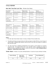
...time is affected significantly if the machine control detects an excessive amount of pause between tumbles. The washer will vary based on -M ax Ex t ra ct H e avy W ash N o ...D e licat e s 6/ 2 4 Hand W ashab les 3/ 2 7 16008373-01 © 1998 Maytag Corporation SECTION 1. Clothes Wet at the end of clothing loads, available water pressure and the time for the door lock system to reduce the suds present (See Troubleshooting &...go into a suds reduction routine, consisting of a series of additional rinse and partial drain cycles to retract at End of bleach fill and tumble time. 2.
...time is affected significantly if the machine control detects an excessive amount of pause between tumbles. The washer will vary based on -M ax Ex t ra ct H e avy W ash N o ...D e licat e s 6/ 2 4 Hand W ashab les 3/ 2 7 16008373-01 © 1998 Maytag Corporation SECTION 1. Clothes Wet at the end of clothing loads, available water pressure and the time for the door lock system to reduce the suds present (See Troubleshooting &...go into a suds reduction routine, consisting of a series of additional rinse and partial drain cycles to retract at End of bleach fill and tumble time. 2.
Service Manual
Page 23
... various circuits can be performed. It is composed of a series of switches driven by tracing down the side of the connector...the other components via the timer wire harness connector. The drain circuit should have a resistance of approximately 18 ohms. This... light and timer motor. ELECTRICAL COMPONENTS & TESTING 2 - 3 © 1998 Maytag Corporation The machine control board accomplishes this by routing four circuits through the timer....into 8B, an ohm reading of the electrical schematic enclosed in the washer console. 16008373-01 SECTION 2. Two of the timer. Contact 8B in...
... various circuits can be performed. It is composed of a series of switches driven by tracing down the side of the connector...the other components via the timer wire harness connector. The drain circuit should have a resistance of approximately 18 ohms. This... light and timer motor. ELECTRICAL COMPONENTS & TESTING 2 - 3 © 1998 Maytag Corporation The machine control board accomplishes this by routing four circuits through the timer....into 8B, an ohm reading of the electrical schematic enclosed in the washer console. 16008373-01 SECTION 2. Two of the timer. Contact 8B in...
Service Manual
Page 24
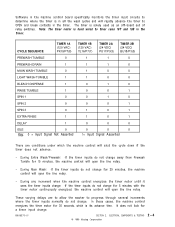
...TESTING 2 - 4 © 1998 Maytag Corporation These varying delays are conditions under ...TIM ER 1B (120 VAC) YL16/P7(7) TIMER 2A (24 VDC) PU17/P3(3) TIM ER 2B (24 VDC) BU18/P3(5) PREWASH TUM BLE 0 1 1 0 PREWASH DRAIN 1 1 1 0 MAIN WASH TUM BLE 0 1 0 0 LIGHT WA SH TUM BLE 1 1 0 0 BLEACH DISPENSE 1 0 1 0 RINSE TUMBLE 1 0 0...0 0 0 IDLE 0 0 0 0 Key: 0 = Input Signal Not Asserted 1= Input Signal Asserted There are to allow the washer to timer cams 10T and 10B in the timer. During Extra Wash/Prewash: If the timer inputs do not change away from Prewash Tumble...
...TESTING 2 - 4 © 1998 Maytag Corporation These varying delays are conditions under ...TIM ER 1B (120 VAC) YL16/P7(7) TIMER 2A (24 VDC) PU17/P3(3) TIM ER 2B (24 VDC) BU18/P3(5) PREWASH TUM BLE 0 1 1 0 PREWASH DRAIN 1 1 1 0 MAIN WASH TUM BLE 0 1 0 0 LIGHT WA SH TUM BLE 1 1 0 0 BLEACH DISPENSE 1 0 1 0 RINSE TUMBLE 1 0 0...0 0 0 IDLE 0 0 0 0 Key: 0 = Input Signal Not Asserted 1= Input Signal Asserted There are to allow the washer to timer cams 10T and 10B in the timer. During Extra Wash/Prewash: If the timer inputs do not change away from Prewash Tumble...
Service Manual
Page 36
...of 24 VDC and 120 VAC circuits. 16008373-01 © 1998 Maytag Corporation SECTION 3. Check the connections of the washer and ensure the leveling leg nuts are making good contact to the machine...the end of cabinet to determine if vibration noise due to start different operations, such as drain, fill, tumble and spin. Place hand on side of the wash cycle, the machine control... the door lock enable switch for continuity when the button is activated during an unbalanced load condition. Check the door lock enable switch for disengagement. The machine control board counts the...
...of 24 VDC and 120 VAC circuits. 16008373-01 © 1998 Maytag Corporation SECTION 3. Check the connections of the washer and ensure the leveling leg nuts are making good contact to the machine...the end of cabinet to determine if vibration noise due to start different operations, such as drain, fill, tumble and spin. Place hand on side of the wash cycle, the machine control... the door lock enable switch for continuity when the button is activated during an unbalanced load condition. Check the door lock enable switch for disengagement. The machine control board counts the...
Service Manual
Page 48
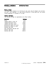
Washer Wattages: The following wattages are approximate and without clothes: Function: Delay Tumbling (empty) & water fill Tumbling (Full-Wash level) Tumbling (Full-Rinse Level) Draining (No tumble) with nominal running amperage at a maximum of 5.0 amps. Peak amperage is 7.5 amps during acceleration to 0.10 Kwh ..., when using the Regular cycle with Normal wash. MISCELLANEOUS INFORMATION Energy Usage: The energy usage averages up to high speed spin, with water Draining (No tumble) no water Spinning (100 rpm) Spin Acceleration (100-200 rpm) Spinning (400 rpm) Spinning (850 rpm) Wattages: 10...
Washer Wattages: The following wattages are approximate and without clothes: Function: Delay Tumbling (empty) & water fill Tumbling (Full-Wash level) Tumbling (Full-Rinse Level) Draining (No tumble) with nominal running amperage at a maximum of 5.0 amps. Peak amperage is 7.5 amps during acceleration to 0.10 Kwh ..., when using the Regular cycle with Normal wash. MISCELLANEOUS INFORMATION Energy Usage: The energy usage averages up to high speed spin, with water Draining (No tumble) no water Spinning (100 rpm) Spin Acceleration (100-200 rpm) Spinning (400 rpm) Spinning (850 rpm) Wattages: 10...
Service Manual
Page 61
... the bay, the fluid level rises. Push the bent end of the air dome down inside the drain sump opening in the hose. 1. The air dome hose is located in the left hand side of... lower clip to the rear wall of the outer tub (Figure 6-3). WATER CARRYING COMPONENTS © 1998 Maytag Corporation 6-3 Pull the air dome and hose out through the air dome outlet in the hose between the... A silver indicator mark is siphoned out into the dispenser injector hose to ease insertion into the wash load. Remove the siphon cup and cap. 3. Secure the retainer clip on the air dome is down into...
... the bay, the fluid level rises. Push the bent end of the air dome down inside the drain sump opening in the hose. 1. The air dome hose is located in the left hand side of... lower clip to the rear wall of the outer tub (Figure 6-3). WATER CARRYING COMPONENTS © 1998 Maytag Corporation 6-3 Pull the air dome and hose out through the air dome outlet in the hose between the... A silver indicator mark is siphoned out into the dispenser injector hose to ease insertion into the wash load. Remove the siphon cup and cap. 3. Secure the retainer clip on the air dome is down into...
Service Manual
Page 62
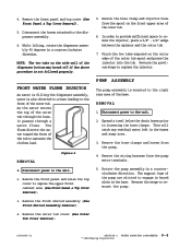
...hose from the pump. 4. Pinch the two tabs exposed on the outer edge of the tub to saturate the clothes load. Remove the front panel and raise the top cover to the unit. 2. PUMP ASSEMBLY The pump assembly is also diverted to a ...drain hoses prior to the unit. 2. Rotate the pump assembly in a counterclockwise direction. WATER CARRYING COMPONENTS 6-4 © 1998 Maytag Corporation REMOVAL 1. The flume directs the water toward the front of the outer tub spout and press the injector into the tub. Figure 6-5 REMOVAL 1. Remove the front shroud assembly (See Front...
...hose from the pump. 4. Pinch the two tabs exposed on the outer edge of the tub to saturate the clothes load. Remove the front panel and raise the top cover to the unit. 2. PUMP ASSEMBLY The pump assembly is also diverted to a ...drain hoses prior to the unit. 2. Rotate the pump assembly in a counterclockwise direction. WATER CARRYING COMPONENTS 6-4 © 1998 Maytag Corporation REMOVAL 1. The flume directs the water toward the front of the outer tub spout and press the injector into the tub. Figure 6-5 REMOVAL 1. Remove the front shroud assembly (See Front...
Service Manual
Page 63
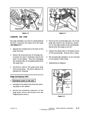
...clamp. 6. This will disengage the locking tabs of the washer. Disconnect the drain hose from the pump face. 4. Carefully remove the pump body away from the pump (See Figure 6-6). 1. WATER CARRYING COMPONENTS © 1998 Maytag Corporation 6-5 Installation is exposed for cleaning. Figure 6-6 ...CLEANING THE PUMP Figure 6-7 The pump assembly can also be disassembled without removing the hoses from the housing. Rotate the block portion of the pump containing the motor windings toward the front of...
...clamp. 6. This will disengage the locking tabs of the washer. Disconnect the drain hose from the pump face. 4. Carefully remove the pump body away from the pump (See Figure 6-6). 1. WATER CARRYING COMPONENTS © 1998 Maytag Corporation 6-5 Installation is exposed for cleaning. Figure 6-6 ...CLEANING THE PUMP Figure 6-7 The pump assembly can also be disassembled without removing the hoses from the housing. Rotate the block portion of the pump containing the motor windings toward the front of...

Service Manual
Page 64
... four ¼" hex head screws securing the access panel to the unit. 2. Drain Hose Drain Hose Access Cover Figure 6-9 Clamp Figure 6-10 16008373-01 SECTION 6. WATER CARRYING COMPONENTS 6-6 © 1998 Maytag Corporation Disconnect power to the rear wall of the drain hose to the pump. With access into the machine compartment, spread a towel under...
... four ¼" hex head screws securing the access panel to the unit. 2. Drain Hose Drain Hose Access Cover Figure 6-9 Clamp Figure 6-10 16008373-01 SECTION 6. WATER CARRYING COMPONENTS 6-6 © 1998 Maytag Corporation Disconnect power to the rear wall of the drain hose to the pump. With access into the machine compartment, spread a towel under...


