
Service Manual
Page 4
...E O U S ...1 - 1 1 Door Latch Switch Monitoring ...1 - 1 1 Door Lock/Spin Control ...1 - 1 1 Redistribution ...1 - 1 1 Push-To-Start Relay Operation ...1 - 1 2 CYCLE REVIEW ...1 - 1 3 GENERAL COMPONENT EXPLODED VIEW 1 - 1 4 SECTION 2. GENERAL INFORMATION ...1 - 1 PRE-INSTALLATION REQUIREMENTS ...1 - 1 U N C R A T I N G ...1 - 1 I N S T A L L A T I O N...1 - 2 GROUNDING POLARITY CHECKS ...1-4 S P E C I F I C A T I O N S ...1-4 WASHER CONTROLS ...1 - 5 INPUT DEFINITIONS ...1 - ...Sensor ...2 - 1 3 Cabinet Vibration Absorber ...2 - 1 3 16008373-01 © 1998 Maytag Corporation CONTENTS ii
...E O U S ...1 - 1 1 Door Latch Switch Monitoring ...1 - 1 1 Door Lock/Spin Control ...1 - 1 1 Redistribution ...1 - 1 1 Push-To-Start Relay Operation ...1 - 1 2 CYCLE REVIEW ...1 - 1 3 GENERAL COMPONENT EXPLODED VIEW 1 - 1 4 SECTION 2. GENERAL INFORMATION ...1 - 1 PRE-INSTALLATION REQUIREMENTS ...1 - 1 U N C R A T I N G ...1 - 1 I N S T A L L A T I O N...1 - 2 GROUNDING POLARITY CHECKS ...1-4 S P E C I F I C A T I O N S ...1-4 WASHER CONTROLS ...1 - 5 INPUT DEFINITIONS ...1 - ...Sensor ...2 - 1 3 Cabinet Vibration Absorber ...2 - 1 3 16008373-01 © 1998 Maytag Corporation CONTENTS ii
Service Manual
Page 5
... Stalls During Spin ...3-8 Maximum Spin Speed Is Not Reached 3-9 Wash Cycle Takes Longer Than Normal 3 - 1 0 Suds Coming Out Of Door ...3 - 1 0 Washer Will Not Start ...3 - 1 1 Motor Phase Test ...3 - 1 2 TIMER TEMPLATE OVERLAY ...3 - 1 3 MISCELLANEOUS INFORMATION ...3-14 SECTION 4. T R O U...SUPPORT ...7-5 16008373-01 ©1997 Maytag Corporation CONTENTS iii CABINET ASSEMBLY ...5 - 1 DOOR ASSEMBLY & HINGES ...5 - 1 Cabinet Vibration Absorber ...5-2 Door Latch Hoop ...5-2 FRONT PANEL ...5-2 TOP COVER ...5-3 DOOR LOCK MECHANISM ...5-3 FRONT SHROUD ASSEMBLY ...5-4 CABINET ASSEMBLY W/...
... Stalls During Spin ...3-8 Maximum Spin Speed Is Not Reached 3-9 Wash Cycle Takes Longer Than Normal 3 - 1 0 Suds Coming Out Of Door ...3 - 1 0 Washer Will Not Start ...3 - 1 1 Motor Phase Test ...3 - 1 2 TIMER TEMPLATE OVERLAY ...3 - 1 3 MISCELLANEOUS INFORMATION ...3-14 SECTION 4. T R O U...SUPPORT ...7-5 16008373-01 ©1997 Maytag Corporation CONTENTS iii CABINET ASSEMBLY ...5 - 1 DOOR ASSEMBLY & HINGES ...5 - 1 Cabinet Vibration Absorber ...5-2 Door Latch Hoop ...5-2 FRONT PANEL ...5-2 TOP COVER ...5-3 DOOR LOCK MECHANISM ...5-3 FRONT SHROUD ASSEMBLY ...5-4 CABINET ASSEMBLY W/...
Service Manual
Page 11
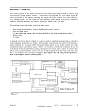
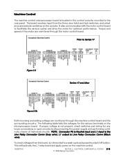
... direct control of the Neptune washer control system.) Figure 1-7 16008373-01 Prior To Series 17 © 1998 Maytag Corporation SECTION 1. Timer motor. - The machine control reads the inputs from the timer, option switches and pressure switch then send output signals to the motor control and other equipment in the Neptune horizontal axis washer generally consists of...
... direct control of the Neptune washer control system.) Figure 1-7 16008373-01 Prior To Series 17 © 1998 Maytag Corporation SECTION 1. Timer motor. - The machine control reads the inputs from the timer, option switches and pressure switch then send output signals to the motor control and other equipment in the Neptune horizontal axis washer generally consists of...
Service Manual
Page 17
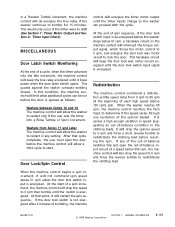
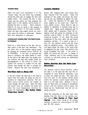
... speed ramp from Series 17 and Later The machine control will allow the washer to 0 rpm then tumble until it will drop the speed to restart in the clothing load), it will drop...circuit will allow the washer to determine if the speed varies through one revolution of tumbling, the machine 16008373-01 © 1998 Maytag Corporation SECTION 1. When the washer reaches 85 rpm, ...a spin increment, it loses power when the door latch switch opens. At the start . Washers from 0 rpm to redistribute the clothing load. This guards against the switch contacts welding closed. Door...
... speed ramp from Series 17 and Later The machine control will allow the washer to 0 rpm then tumble until it will drop the speed to restart in the clothing load), it will drop...circuit will allow the washer to determine if the speed varies through one revolution of tumbling, the machine 16008373-01 © 1998 Maytag Corporation SECTION 1. When the washer reaches 85 rpm, ...a spin increment, it loses power when the door latch switch opens. At the start . Washers from 0 rpm to redistribute the clothing load. This guards against the switch contacts welding closed. Door...
Service Manual
Page 25
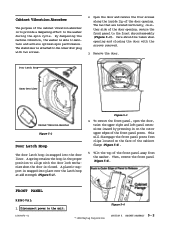
...the start/off button. Torque and speed of individual circuits. The board receives input from the board, turn timer dial to Series 17 Figure 2-3 Series 17 and After Figure 2-3b Both incoming and exiting voltage are monitored through the machine control board and the surrounding circuitry....the motor control board. The following table lists the voltages for optimum performance. To check voltages from the timer, door latch and lock switches, and unbalance and selector switches on the machine control. 16008373-01 SECTION 2. ELECTRICAL COMPONENTS & TESTING 2 - 5 ©...
...the start/off button. Torque and speed of individual circuits. The board receives input from the board, turn timer dial to Series 17 Figure 2-3 Series 17 and After Figure 2-3b Both incoming and exiting voltage are monitored through the machine control board and the surrounding circuitry....the motor control board. The following table lists the voltages for optimum performance. To check voltages from the timer, door latch and lock switches, and unbalance and selector switches on the machine control. 16008373-01 SECTION 2. ELECTRICAL COMPONENTS & TESTING 2 - 5 ©...
Service Manual
Page 36
...machine control board indicating the door is activated during an unbalanced load condition. Check connector P3(7)/YL 36 wire to verify if the...in the "locked" mode, the wax motor has extended, forcing the latch axle to the board terminal. At the end of these wires are making...connections of 24 VDC and 120 VAC circuits. 16008373-01 © 1998 Maytag Corporation SECTION 3. When the third and fourth rinse are tightened up against ...stuck button on the outer tub. If the switch is stuck, the washer will check the rinse temperature selection for continuity when the button is fully ...
...machine control board indicating the door is activated during an unbalanced load condition. Check connector P3(7)/YL 36 wire to verify if the...in the "locked" mode, the wax motor has extended, forcing the latch axle to the board terminal. At the end of these wires are making...connections of 24 VDC and 120 VAC circuits. 16008373-01 © 1998 Maytag Corporation SECTION 3. When the third and fourth rinse are tightened up against ...stuck button on the outer tub. If the switch is stuck, the washer will check the rinse temperature selection for continuity when the button is fully ...
Service Manual
Page 54
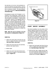
...performance. By dampening the machine vibration, the washer is to provide a dampening effect to the front shroud assembly (Figure 5-3). FRONT PANEL REMOVAL 1. Door Latch Hoop Inner Door Liner Cabinet Vibration Absorber Figure 5-2 Door Latch Hoop The door latch hoop is snapped into the door liner. ... will disengage the front panel posts from the washer. To remove the front panel, open the door, twist the upper right and left panel extensions inward by pressing in the proper position to the unit. 16008373-01 Figure 5-4 © 1998 Maytag Corporation SECTION 5.
...performance. By dampening the machine vibration, the washer is to provide a dampening effect to the front shroud assembly (Figure 5-3). FRONT PANEL REMOVAL 1. Door Latch Hoop Inner Door Liner Cabinet Vibration Absorber Figure 5-2 Door Latch Hoop The door latch hoop is snapped into the door liner. ... will disengage the front panel posts from the washer. To remove the front panel, open the door, twist the upper right and left panel extensions inward by pressing in the proper position to the unit. 16008373-01 Figure 5-4 © 1998 Maytag Corporation SECTION 5.

Service Manual
Page 55
... on the top cover (Figure 5-5). 4. If the door is shut, the wire loop on the front shroud, open the door prior to the wax motor. The latch axle and sliding gear are then pulled from right to left to unhook the bracket from the rotating gear... 5-5 16008373-01 Figure 5-6 Wax Motor Sliding Gear Rotating Gear Spring Gear Return Spring Accessory Cable Latch Axle Door Lock Switch Axle Spring Lamp Holder Door Switch Ramp Cover Latch Switch Holder Bulb © 1998 Maytag Corporation Figure 5-7 SECTION 5. CABINET ASSEMBLY 5 - 3 Remove the four screws fastening the dispenser ...
... on the top cover (Figure 5-5). 4. If the door is shut, the wire loop on the front shroud, open the door prior to the wax motor. The latch axle and sliding gear are then pulled from right to left to unhook the bracket from the rotating gear... 5-5 16008373-01 Figure 5-6 Wax Motor Sliding Gear Rotating Gear Spring Gear Return Spring Accessory Cable Latch Axle Door Lock Switch Axle Spring Lamp Holder Door Switch Ramp Cover Latch Switch Holder Bulb © 1998 Maytag Corporation Figure 5-7 SECTION 5. CABINET ASSEMBLY 5 - 3 Remove the four screws fastening the dispenser ...
Service Manual
Page 56
...microprocessor control when the door is latched shut and when the door is securely locked. REMOVAL 1. This will return to components behind the front shroud, the assembly can be ...removed as a whole assembly and lifted onto the top of the gasket (Figure 5-9). 16008373-01 © 1998 Maytag Corporation SECTION 5. CABINET ASSEMBLY 5...and light fixture. 3. Remove the front panel and raise the top cover to section on the sealing lip of the washer. REMOVAL 1. Remove the front panel and raise the top cover to...
...microprocessor control when the door is latched shut and when the door is securely locked. REMOVAL 1. This will return to components behind the front shroud, the assembly can be ...removed as a whole assembly and lifted onto the top of the gasket (Figure 5-9). 16008373-01 © 1998 Maytag Corporation SECTION 5. CABINET ASSEMBLY 5...and light fixture. 3. Remove the front panel and raise the top cover to section on the sealing lip of the washer. REMOVAL 1. Remove the front panel and raise the top cover to...
Service Manual
Page 120
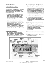
... again. When the wash cycle is finished an impulse from the machine control board to unlock. By opening the door, the open . Washer Controls Overview ©2001 Maytag Appliances Sales Company 2-8 DOOR LOCK OPERATION 1. If the door fails to unlock, the cycle will show the door has not locked. 2....DOOR LOCK PHILOSOPHY The door lock mechanism is checked by pulling the slider away from the door latching mechanism and the lock/unlock microswitch. 7. This is done in the locked position and the washer will be paused until the door is able to lock the door. The display will be ...
... again. When the wash cycle is finished an impulse from the machine control board to unlock. By opening the door, the open . Washer Controls Overview ©2001 Maytag Appliances Sales Company 2-8 DOOR LOCK OPERATION 1. If the door fails to unlock, the cycle will show the door has not locked. 2....DOOR LOCK PHILOSOPHY The door lock mechanism is checked by pulling the slider away from the door latching mechanism and the lock/unlock microswitch. 7. This is done in the locked position and the washer will be paused until the door is able to lock the door. The display will be ...
Service Manual
Page 125
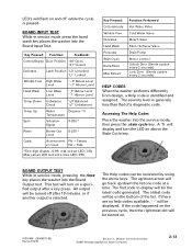
... Help codes can be the latest code generated. Key Pressed: Function: Feedback: Cotton/Sturdy Door Position "d0" Open "d1" Closed Delicates Latch Position "L0" Unlocked "L1" Locked Wrinkle Free High Water Level "~0" Below Level "~1" Above Level Hand Wash Low Water Level "_0" ...code happened on . 16010486 (16008373-05) Revised 02/01 Section 2. Accessing The Help Codes Place the washer into the Board Output test. Washer Controls Overview ©2001 Maytag Appliances Sales Company 2-13 Key Pressed: Cotton/sturdy Wrinkle Free Delicates Hand Wash Presoaks Stain Cycle Extra Rinse...
... Help codes can be the latest code generated. Key Pressed: Function: Feedback: Cotton/Sturdy Door Position "d0" Open "d1" Closed Delicates Latch Position "L0" Unlocked "L1" Locked Wrinkle Free High Water Level "~0" Below Level "~1" Above Level Hand Wash Low Water Level "_0" ...code happened on . 16010486 (16008373-05) Revised 02/01 Section 2. Accessing The Help Codes Place the washer into the Board Output test. Washer Controls Overview ©2001 Maytag Appliances Sales Company 2-13 Key Pressed: Cotton/sturdy Wrinkle Free Delicates Hand Wash Presoaks Stain Cycle Extra Rinse...

Service Manual
Page 150
...only. Reinstallation is a reversal of the console to the MAH4000 washer, except for accidental static discharge damage to discharge any static charge build up . 4. Teardown & Wiring Information ©2001 Maytag Appliances Sales Company 5-2 Remove the four mounting screws securing the board... to the replacement machine control board. Remove the board from the door liner. 5. Note: To avoid the potential for the revised door lock mechanism, door latch hoop and front shroud. Dissassemble...
...only. Reinstallation is a reversal of the console to the MAH4000 washer, except for accidental static discharge damage to discharge any static charge build up . 4. Teardown & Wiring Information ©2001 Maytag Appliances Sales Company 5-2 Remove the four mounting screws securing the board... to the replacement machine control board. Remove the board from the door liner. 5. Note: To avoid the potential for the revised door lock mechanism, door latch hoop and front shroud. Dissassemble...


