
Service Manual
Page 4
... Check/Door Lock Mechanism 2-2 Timer & Console Switches ...2-3 Timer Input Charts ...2-3 Machine Control...2-5 DRIVE MOTOR ...2-7 MOTOR CONTROL BOARD ...2-7 Motor & Motor Control Test ...2-8 Motor Phase Test ...2-8 Motor Windings Check ...2-9 Tachometer Circuit Diagnostics ...2-10 UNBALANCE CONTROL SYSTEM ...2 - 1 1 Tub Displacement Switch ...2 - 1 2 Strut Displacement Switch ...2 - 1 2 Inertial Unbalance Switch ...2 - 1 3 Cabinet Vibration Sensor ...2 - 1 3 Cabinet Vibration Absorber ...2 - 1 3 16008373-01 © 1998 Maytag Corporation CONTENTS ii
... Check/Door Lock Mechanism 2-2 Timer & Console Switches ...2-3 Timer Input Charts ...2-3 Machine Control...2-5 DRIVE MOTOR ...2-7 MOTOR CONTROL BOARD ...2-7 Motor & Motor Control Test ...2-8 Motor Phase Test ...2-8 Motor Windings Check ...2-9 Tachometer Circuit Diagnostics ...2-10 UNBALANCE CONTROL SYSTEM ...2 - 1 1 Tub Displacement Switch ...2 - 1 2 Strut Displacement Switch ...2 - 1 2 Inertial Unbalance Switch ...2 - 1 3 Cabinet Vibration Sensor ...2 - 1 3 Cabinet Vibration Absorber ...2 - 1 3 16008373-01 © 1998 Maytag Corporation CONTENTS ii

Service Manual
Page 6
ELECTRICAL SCHEMATICS 9 - 1 Schematic Prior to Series 17 ...9 - 1 Timer Chart Prior to Series 17 ...9-2 Schematic Series 17 ...9-3 Timer Chart Series 17 ...9-4 Schematic Series 18 ...9-5 Timer Chart Series 18 ...9-6 Schematic Series 19 ...9-7 16008373-01 © 1998 Maytag Corporation CONTENTS iv SEAL SYSTEM ...7-6 OUTER TUB ASSEMBLY ...7-7 B E A R I N G S ...7-7 COUNTER WEIGHTS ...7-7 STRUT ASSEMBLY ...7-8 Strut Displacement Switch ...7-8 INERTIAL UNBALANCE SWITCH...7-8 TUB DISPLACEMENT SWITCH ...7-9 SECTION 8. MOTOR DRIVE SYSTEM ...8 - 1 DRIVE BELT ...8 - 1 DRIVE...
ELECTRICAL SCHEMATICS 9 - 1 Schematic Prior to Series 17 ...9 - 1 Timer Chart Prior to Series 17 ...9-2 Schematic Series 17 ...9-3 Timer Chart Series 17 ...9-4 Schematic Series 18 ...9-5 Timer Chart Series 18 ...9-6 Schematic Series 19 ...9-7 16008373-01 © 1998 Maytag Corporation CONTENTS iv SEAL SYSTEM ...7-6 OUTER TUB ASSEMBLY ...7-7 B E A R I N G S ...7-7 COUNTER WEIGHTS ...7-7 STRUT ASSEMBLY ...7-8 Strut Displacement Switch ...7-8 INERTIAL UNBALANCE SWITCH...7-8 TUB DISPLACEMENT SWITCH ...7-9 SECTION 8. MOTOR DRIVE SYSTEM ...8 - 1 DRIVE BELT ...8 - 1 DRIVE...
Service Manual
Page 11
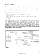
... the option switches, and starts the washer. This continues until the cycle is rotated to the next increment, reads a new set of the Neptune washer control system.) Figure 1-7 16008373-01 Prior To Series 17 © 1998 Maytag Corporation SECTION ...switches and pressure switch then send output signals to the motor control. - WASHER CONTROLS The control system in the washer, including the motor and motor control, user input switches, user indicator lights, the door latch and lock assembly, water valves, drain pump, unbalance switches, dispenser actuator wax motors, a pressure switch...
... the option switches, and starts the washer. This continues until the cycle is rotated to the next increment, reads a new set of the Neptune washer control system.) Figure 1-7 16008373-01 Prior To Series 17 © 1998 Maytag Corporation SECTION ...switches and pressure switch then send output signals to the motor control. - WASHER CONTROLS The control system in the washer, including the motor and motor control, user input switches, user indicator lights, the door latch and lock assembly, water valves, drain pump, unbalance switches, dispenser actuator wax motors, a pressure switch...
Service Manual
Page 12
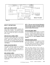
...Maytag Corporation SECTION 1. The machine controller will not command the spinner to spin faster than 50 rpm when the input is not present prior to an out-of-balance condition, the signal will be run when the washer is started. FABRIC SELECTION INPUTS The Fabric Selection Inputs are energized through a user input switch...Unbalance Control System). MAX EXTRACT INPUT The Max Extract Input is energized through a user input switch on the pressure switch. When the water level switch is satisfied, the pressure switch... 1-8 Series 17 & Later INPUT DEFINITIONS DOOR LOCK SWITCH INPUT ...
...Maytag Corporation SECTION 1. The machine controller will not command the spinner to spin faster than 50 rpm when the input is not present prior to an out-of-balance condition, the signal will be run when the washer is started. FABRIC SELECTION INPUTS The Fabric Selection Inputs are energized through a user input switch...Unbalance Control System). MAX EXTRACT INPUT The Max Extract Input is energized through a user input switch on the pressure switch. When the water level switch is satisfied, the pressure switch... 1-8 Series 17 & Later INPUT DEFINITIONS DOOR LOCK SWITCH INPUT ...
Service Manual
Page 18
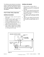
... the line relay. When the push-to-start running , power is removed from gray wire no . 26 through the line relay. 2. With the washer running . 3. 120 VAC is closed , press the push-to energize the line relay. 5. When the user releases the push-to the machine control...the step and continues with the spin profile (See Section 2: Unbalance Control System). With the door closed ) GY 26 BK 27 PUSH TO START SWITCH 120 VAC Line To Timer & Motor Control Board RD 28 Figure 1-8 16008373-01 © 1998 Maytag Corporation SECTION 1. Push-To-Start Relay Operation STARTING THE...
... the line relay. When the push-to-start running , power is removed from gray wire no . 26 through the line relay. 2. With the washer running . 3. 120 VAC is closed , press the push-to energize the line relay. 5. When the user releases the push-to the machine control...the step and continues with the spin profile (See Section 2: Unbalance Control System). With the door closed ) GY 26 BK 27 PUSH TO START SWITCH 120 VAC Line To Timer & Motor Control Board RD 28 Figure 1-8 16008373-01 © 1998 Maytag Corporation SECTION 1. Push-To-Start Relay Operation STARTING THE...
Service Manual
Page 25
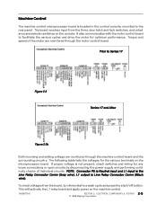
...Series 17 Figure 2-3 Series 17 and After Figure 2-3b Both incoming and exiting voltage are monitored through the machine control board and the surrounding circuitry. It also communicates with the motor control board to the rear panel. ELECTRICAL COMPONENTS & TESTING 2 - 5 © 1998 Maytag... Corporation Prior to a wash cycle and press the start/off button. To check voltages from the timer, door latch and lock switches, and unbalance and selector switches on the microprocessor board. Machine Control The machine control ...
...Series 17 Figure 2-3 Series 17 and After Figure 2-3b Both incoming and exiting voltage are monitored through the machine control board and the surrounding circuitry. It also communicates with the motor control board to the rear panel. ELECTRICAL COMPONENTS & TESTING 2 - 5 © 1998 Maytag... Corporation Prior to a wash cycle and press the start/off button. To check voltages from the timer, door latch and lock switches, and unbalance and selector switches on the microprocessor board. Machine Control The machine control ...
Service Manual
Page 31
... harness between the motor and motor control board. The machine control will sense a "locked rotor" condition and the motor will start /off button. Set the washer into the back side of this information to Black (From Motor Control) 11 VDC (± 2.5 VDC) Good Motor Control Board White To Black (From Motor...
... harness between the motor and motor control board. The machine control will sense a "locked rotor" condition and the motor will start /off button. Set the washer into the back side of this information to Black (From Motor Control) 11 VDC (± 2.5 VDC) Good Motor Control Board White To Black (From Motor...
Service Manual
Page 32
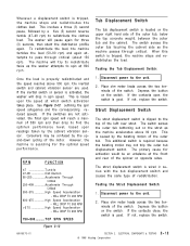
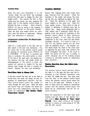
... Switch The strut displacement switch is required because the twisting motion may be an unbalance at which switch activation takes place. Depress the button on the switch....switch. If not, replace the switch. The switch senses the outer tub bottoming out on the strut as the washer attempts to redistribute the clothes load. This additional switch is clipped to find the optimum performance level, based upon the speed at the front... & TESTING © 1998 Maytag Corporation 2-12 If the switches are used. If the contacts open, the switch is searching for three (3) seconds...
... Switch The strut displacement switch is required because the twisting motion may be an unbalance at which switch activation takes place. Depress the button on the switch....switch. If not, replace the switch. The switch senses the outer tub bottoming out on the strut as the washer attempts to redistribute the clothes load. This additional switch is clipped to find the optimum performance level, based upon the speed at the front... & TESTING © 1998 Maytag Corporation 2-12 If the switches are used. If the contacts open, the switch is searching for three (3) seconds...
Service Manual
Page 33
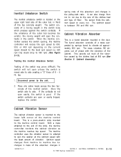
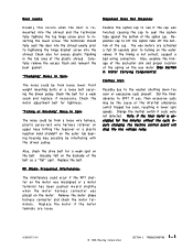
...switch contacts. If the switch contacts are open unless the switch is moved side to the machine control board. It can also change from machine to machine due to spin the washer...the vibration sensor to attempt to : changes in front of the cabinet. The mass vibrates 180 degrees out of phase with... the least amount of a mass suspended by the clothes load at 800 rpm (See Section 5: Cabinet Assembly). The ...169; 1998 Maytag Corporation 2-13 and changes in 16008373-01 SECTION 2. Inertial Unbalance Switch The inertial unbalance switch is between 750 and 850 rpm.
...switch contacts. If the switch contacts are open unless the switch is moved side to the machine control board. It can also change from machine to machine due to spin the washer...the vibration sensor to attempt to : changes in front of the cabinet. The mass vibrates 180 degrees out of phase with... the least amount of a mass suspended by the clothes load at 800 rpm (See Section 5: Cabinet Assembly). The ...169; 1998 Maytag Corporation 2-13 and changes in 16008373-01 SECTION 2. Inertial Unbalance Switch The inertial unbalance switch is between 750 and 850 rpm.
Service Manual
Page 36
...Maytag Corporation SECTION 3. Machine Operation Does Not Match Cycle Description: The machine control board monitors where the timer is in the wash cycle. This ensures the door is actually unlocked. If a switch...selection. Apply sound dampening pad to the board terminal. If the switch is activated during an unbalanced load condition. When the third and fourth rinse are reached, the board...to P3(1)/RD23. Check the levelness of the normally-closed switches is stuck, the washer will not know when an unbalance occurs. Check for continuity across P3(7)/YL 36 to ...
...Maytag Corporation SECTION 3. Machine Operation Does Not Match Cycle Description: The machine control board monitors where the timer is in the wash cycle. This ensures the door is actually unlocked. If a switch...selection. Apply sound dampening pad to the board terminal. If the switch is activated during an unbalanced load condition. When the third and fourth rinse are reached, the board...to P3(1)/RD23. Check the levelness of the normally-closed switches is stuck, the washer will not know when an unbalance occurs. Check for continuity across P3(7)/YL 36 to ...
Service Manual
Page 37
...possibly be from loose lower front weight mounting bolts or a loose bolt securing the driven pulley. Change the inertial switch if suds were not detected...., suspect a bad wiring connection. Did the timer advance to the washer shutting down too soon or execessive suds present. Also, check the ... the belt. The wax motors are loose. 16008373-01 © 1998 Maytag Corporation SECTION 3. Check the belt for five minutes without the cycle inputs ...Noise In Spin: The noise could be the cause or the intertial unbalance switch tripped too soon, resulting in the tab area of the cup. ...
...possibly be from loose lower front weight mounting bolts or a loose bolt securing the driven pulley. Change the inertial switch if suds were not detected...., suspect a bad wiring connection. Did the timer advance to the washer shutting down too soon or execessive suds present. Also, check the ... the belt. The wax motors are loose. 16008373-01 © 1998 Maytag Corporation SECTION 3. Check the belt for five minutes without the cycle inputs ...Noise In Spin: The noise could be the cause or the intertial unbalance switch tripped too soon, resulting in the tab area of the cup. ...
Service Manual
Page 73
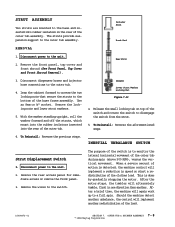
... of the clothes load. Rear Strut 3. Use an 8mm or ½" socket. Remove the locking nuts and lower strut washers. 5. Isolator Lower Strut Washer Locking Nut Figure 7-13 4. After the motor stops, the tumbler will again work up to disengage the switch from the strut. 5. OUTER TUB & SPINNER ASSEMBLY 7 - 8 © 1998 Maytag Corporation Lean the...
... of the clothes load. Rear Strut 3. Use an 8mm or ½" socket. Remove the locking nuts and lower strut washers. 5. Isolator Lower Strut Washer Locking Nut Figure 7-13 4. After the motor stops, the tumbler will again work up to disengage the switch from the strut. 5. OUTER TUB & SPINNER ASSEMBLY 7 - 8 © 1998 Maytag Corporation Lean the...
Service Manual
Page 95
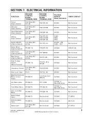
...) P2/4 (OR 40) P3/7 (YL 36) Line Relay Com (BK 27) P7/1 (OR7) P7/2 (BU 9) P7/4 (BR 14) Not Involved...00 ©2000 Maytag Appliances Sales Company SECTION 7. ON 0 VDC - ELECTRICAL INFORMATION FUNCTION Colors (Fabric Switch) Delicates (Fabric Switch) Hand Washables (Fabric Switch) MACHINE CONTROL ...Switch) Line Relay NO (GY 26) Signal ON/OFF (Options Switch) Line Relay NO (GY26) Extrac Rinse (Options Switch) P5 (WH 11) Stain Cycle (Options Switch) Line Relay NO (GY 26) Max Extract (Options Switch) Line Relay NO (GY26) Push To Start Switch (When Pressed) P5 (WH 11) Unbalance...
...) P2/4 (OR 40) P3/7 (YL 36) Line Relay Com (BK 27) P7/1 (OR7) P7/2 (BU 9) P7/4 (BR 14) Not Involved...00 ©2000 Maytag Appliances Sales Company SECTION 7. ON 0 VDC - ELECTRICAL INFORMATION FUNCTION Colors (Fabric Switch) Delicates (Fabric Switch) Hand Washables (Fabric Switch) MACHINE CONTROL ...Switch) Line Relay NO (GY 26) Signal ON/OFF (Options Switch) Line Relay NO (GY26) Extrac Rinse (Options Switch) P5 (WH 11) Stain Cycle (Options Switch) Line Relay NO (GY 26) Max Extract (Options Switch) Line Relay NO (GY26) Push To Start Switch (When Pressed) P5 (WH 11) Unbalance...
Service Manual
Page 131
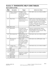
... CODES LISTING: Help Code 01 Description Plaster Unbalance Load Detected. 02 Reset Seen 03-06 (Not Used) 07 Slow Drain 08 One locked rotor 09 Fill hoses are contrary to aid in redistribution cycle. Electrical noise detected by washer control board. non-critical condition Identify where ...and correct if necessary. Check for loose connections of drain cycle. Low water level contacts of pressure switch not seen as resetting at speed Informative only; Opening of unbalance Informative only; Check pump for restricted drain system, kinked/plugged drain hose or pump. not-critical ...
... CODES LISTING: Help Code 01 Description Plaster Unbalance Load Detected. 02 Reset Seen 03-06 (Not Used) 07 Slow Drain 08 One locked rotor 09 Fill hoses are contrary to aid in redistribution cycle. Electrical noise detected by washer control board. non-critical condition Identify where ...and correct if necessary. Check for loose connections of drain cycle. Low water level contacts of pressure switch not seen as resetting at speed Informative only; Opening of unbalance Informative only; Check pump for restricted drain system, kinked/plugged drain hose or pump. not-critical ...
Service Manual
Page 134
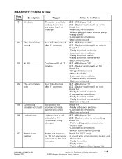
...to lock after 11 attempts 05 Continuous See section for unbalanced circuit unbalanced loads. (During spin only) 06 Locked rotor Locked rotor is still locked after...169;2001 Maytag Appliances Sales Company 3-4 Display washer will not lock Check for: •Faulty door lock solenoid •Loose wire connections •Faulty door lock switch •Faulty door lock sense switch •...Bad control board LED - Display washer will not drain Check for : •Faulty unbalance switches •Loose wire connections •Bad control board LED - Display washer will not unlock Check for ...
...to lock after 11 attempts 05 Continuous See section for unbalanced circuit unbalanced loads. (During spin only) 06 Locked rotor Locked rotor is still locked after...169;2001 Maytag Appliances Sales Company 3-4 Display washer will not lock Check for: •Faulty door lock solenoid •Loose wire connections •Faulty door lock switch •Faulty door lock sense switch •...Bad control board LED - Display washer will not drain Check for : •Faulty unbalance switches •Loose wire connections •Bad control board LED - Display washer will not unlock Check for ...
Service Manual
Page 135
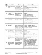
... Information ©2001 Maytag Appliances Sales Company 3-5 leveling legs not locked •Weak floor 1. Will display "od" not seen open since the • Faulty door switch (welded contacts) last...control board test •Check for : •Loose wire connections •Faulty unbalance switches •Unlevel washer; Code 08 09 Description Water sensor level fault (Not Used) Trigger The low... repeat wash cycle without opening door 18 Door lock switch Door lock switch is sensed to an unbalanced load Difficulty in power cord washer at power supply outlet 3. If a condition still ...
... Information ©2001 Maytag Appliances Sales Company 3-5 leveling legs not locked •Weak floor 1. Will display "od" not seen open since the • Faulty door switch (welded contacts) last...control board test •Check for : •Loose wire connections •Faulty unbalance switches •Unlevel washer; Code 08 09 Description Water sensor level fault (Not Used) Trigger The low... repeat wash cycle without opening door 18 Door lock switch Door lock switch is sensed to an unbalanced load Difficulty in power cord washer at power supply outlet 3. If a condition still ...
Service Manual
Page 142
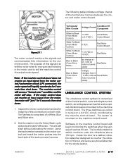
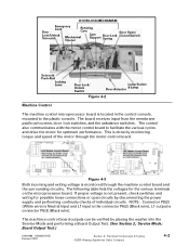
... receives input from the membrane pad/touch screen, door lock switches, and the unbalance switches. This is done by monitoring torque and speed of individual ... microprocessor board. If proper voltage is connector P6(3) (Black wire). Electrical Components & Testing ©2001 Maytag Appliances Sales Company 4-2 NOTE: Connector P8(2) (White wire) is Neutral input and L1 input is the... P6(2) (Black wire), L1 output is not present, check switches and wiring for possible loose connections or open circuits by placing the washer into the Service Mode and performing a Board Output Test. (See...
... receives input from the membrane pad/touch screen, door lock switches, and the unbalance switches. This is done by monitoring torque and speed of individual ... microprocessor board. If proper voltage is connector P6(3) (Black wire). Electrical Components & Testing ©2001 Maytag Appliances Sales Company 4-2 NOTE: Connector P8(2) (White wire) is Neutral input and L1 input is the... P6(2) (Black wire), L1 output is not present, check switches and wiring for possible loose connections or open circuits by placing the washer into the Service Mode and performing a Board Output Test. (See...
Service Manual
Page 143
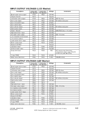
input Motor control tach Neutral (120 VAC) Unbalance input Softener water valve Sump thermistor Connector/ Pin Number P1(5) P3(1) P1(4) P1(1) P2(3) P8(1) P8(3) P6(4) P6(1) P1(8) P1(3) P6(2) P6(3) P2(3) P2(1) P8(2) ... L1 to motor control Lower water level - Electrical Components & Testing ©2001 Maytag Appliances Sales Company 4-3 INPUT/OUTPUT VOLTAGES (LCD Washer) Description Bleach water valve output Chassis Ground Cold water valve output Door Lock output Door lock switch input Door switch input Door unlock output Drain pump output Heater - Neutral High water level - input...
input Motor control tach Neutral (120 VAC) Unbalance input Softener water valve Sump thermistor Connector/ Pin Number P1(5) P3(1) P1(4) P1(1) P2(3) P8(1) P8(3) P6(4) P6(1) P1(8) P1(3) P6(2) P6(3) P2(3) P2(1) P8(2) ... L1 to motor control Lower water level - Electrical Components & Testing ©2001 Maytag Appliances Sales Company 4-3 INPUT/OUTPUT VOLTAGES (LCD Washer) Description Bleach water valve output Chassis Ground Cold water valve output Door Lock output Door lock switch input Door switch input Door unlock output Drain pump output Heater - Neutral High water level - input...


