
Service Manual
Page 5
CABINET ASSEMBLY ...5 - 1 DOOR ASSEMBLY & HINGES ...5 - 1 Cabinet Vibration Absorber ...5-2 Door Latch Hoop ...5-2 FRONT PANEL ...5-2 TOP COVER ...5-3 DOOR LOCK MECHANISM ...5-3 FRONT SHROUD ASSEMBLY ...5-4 CABINET ASSEMBLY W/REAR ACCESS PANEL 5-5 SECTION 6. S E C T I N G ...3 - 1 DIAGNOSTIC FLOW CHARTS...3-4 Fills and Will Not Tumble ...3-4 Washer Overfills ...3-5 Washer Will Not Spin ...3-6 Machine Stalls During Spin ...3-8 Maximum Spin Speed Is Not Reached 3-9 Wash Cycle Takes Longer Than Normal 3 - 1 0 Suds Coming Out Of Door ...3 - 1 0 Washer Will Not...
CABINET ASSEMBLY ...5 - 1 DOOR ASSEMBLY & HINGES ...5 - 1 Cabinet Vibration Absorber ...5-2 Door Latch Hoop ...5-2 FRONT PANEL ...5-2 TOP COVER ...5-3 DOOR LOCK MECHANISM ...5-3 FRONT SHROUD ASSEMBLY ...5-4 CABINET ASSEMBLY W/REAR ACCESS PANEL 5-5 SECTION 6. S E C T I N G ...3 - 1 DIAGNOSTIC FLOW CHARTS...3-4 Fills and Will Not Tumble ...3-4 Washer Overfills ...3-5 Washer Will Not Spin ...3-6 Machine Stalls During Spin ...3-8 Maximum Spin Speed Is Not Reached 3-9 Wash Cycle Takes Longer Than Normal 3 - 1 0 Suds Coming Out Of Door ...3 - 1 0 Washer Will Not...
Service Manual
Page 11
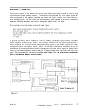
...its set of the Neptune washer control system.) Figure 1-7 16008373-01 Prior To Series 17 © 1998 Maytag Corporation SECTION 1. Timer motor. - On Light. This continues until the cycle is rotated to other components based upon them. GENERAL INFORMATION 1-5 Door lock wax motor. ... reads the inputs from the timer and pressure switch. - WASHER CONTROLS The control system in the washer, including the motor and motor control, user input switches, user indicator lights, the door latch and lock assembly, water valves, drain pump, unbalance switches, dispenser actuator wax...
...its set of the Neptune washer control system.) Figure 1-7 16008373-01 Prior To Series 17 © 1998 Maytag Corporation SECTION 1. Timer motor. - On Light. This continues until the cycle is rotated to other components based upon them. GENERAL INFORMATION 1-5 Door lock wax motor. ... reads the inputs from the timer and pressure switch. - WASHER CONTROLS The control system in the washer, including the motor and motor control, user input switches, user indicator lights, the door latch and lock assembly, water valves, drain pump, unbalance switches, dispenser actuator wax...
Service Manual
Page 54
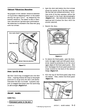
... front shroud assembly (Figure 5-3). The stabilizer is attached to the washer during the spin cycle. Remove the door. Then, remove the front panel (Figure 5-4). Care should be taken when opening . Disconnect power to maintain and achieve optimum spin performance. A plastic support is snapped into the door liner. Door Latch Hoop Inner Door Liner Cabinet Vibration Absorber Figure 5-2 Door Latch Hoop The door latch...
... front shroud assembly (Figure 5-3). The stabilizer is attached to the washer during the spin cycle. Remove the door. Then, remove the front panel (Figure 5-4). Care should be taken when opening . Disconnect power to maintain and achieve optimum spin performance. A plastic support is snapped into the door liner. Door Latch Hoop Inner Door Liner Cabinet Vibration Absorber Figure 5-2 Door Latch Hoop The door latch...

Service Manual
Page 55
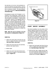
... cover and tilt the top cover toward the rear of the sliding gear will cool and relax the piston on the front shroud, open the door prior to the wax motor. The piston in the top cover lip (Figure 5-6). 5. Remove the four screws fastening the...01 Figure 5-6 Wax Motor Sliding Gear Rotating Gear Spring Gear Return Spring Accessory Cable Latch Axle Door Lock Switch Axle Spring Lamp Holder Door Switch Ramp Cover Latch Switch Holder Bulb © 1998 Maytag Corporation Figure 5-7 SECTION 5. CABINET ASSEMBLY 5 - 3 At the end of the rotating gear (normally takes about 45-60...
... cover and tilt the top cover toward the rear of the sliding gear will cool and relax the piston on the front shroud, open the door prior to the wax motor. The piston in the top cover lip (Figure 5-6). 5. Remove the four screws fastening the...01 Figure 5-6 Wax Motor Sliding Gear Rotating Gear Spring Gear Return Spring Accessory Cable Latch Axle Door Lock Switch Axle Spring Lamp Holder Door Switch Ramp Cover Latch Switch Holder Bulb © 1998 Maytag Corporation Figure 5-7 SECTION 5. CABINET ASSEMBLY 5 - 3 At the end of the rotating gear (normally takes about 45-60...
Service Manual
Page 56
... of the washer. Remove the wires from around the inside perimeter of the gasket (Figure 5-9). 16008373-01 © 1998 Maytag Corporation SECTION 5. This will return to the tub cover, spin basket, sump area and etc.. Remove the front panel and ...front shroud, the assembly can be removed as a whole assembly and lifted onto the top of the door assembly, front panel and door lock mechanism. An emergency access cord (filament) is attached to the sliding gear, should the wax motor fail in the door lock mechanism inform the machine microprocessor control when the door is latched...
... of the washer. Remove the wires from around the inside perimeter of the gasket (Figure 5-9). 16008373-01 © 1998 Maytag Corporation SECTION 5. This will return to the tub cover, spin basket, sump area and etc.. Remove the front panel and ...front shroud, the assembly can be removed as a whole assembly and lifted onto the top of the door assembly, front panel and door lock mechanism. An emergency access cord (filament) is attached to the sliding gear, should the wax motor fail in the door lock mechanism inform the machine microprocessor control when the door is latched...

Service Manual
Page 150
Note: To avoid the potential for the revised door lock mechanism, door latch hoop and front shroud. This can be properly grounded prior to handling the board. Squeeze the side tabs to fill a cavity void in this ...latch hoop support and spring. Figure 5-5 The cover plug simply fills a void area in the console for simplicity reasons, we will address only the exceptions in the console. REMOVAL 1. Remove the board from the washer. 2. Teardown & Wiring Information ©2001 Maytag Appliances Sales Company 5-2 for cosmetic purposes only. Remove the door assembly...
Note: To avoid the potential for the revised door lock mechanism, door latch hoop and front shroud. This can be properly grounded prior to handling the board. Squeeze the side tabs to fill a cavity void in this ...latch hoop support and spring. Figure 5-5 The cover plug simply fills a void area in the console for simplicity reasons, we will address only the exceptions in the console. REMOVAL 1. Remove the board from the washer. 2. Teardown & Wiring Information ©2001 Maytag Appliances Sales Company 5-2 for cosmetic purposes only. Remove the door assembly...


