
Service Manual
Page 4
... & Console Switches ...2-3 Timer Input Charts ...2-3 Machine Control...2-5 DRIVE MOTOR ...2-7 MOTOR CONTROL BOARD ...2-7 Motor & Motor Control Test ...2-8 Motor Phase Test ...2-8 Motor Windings Check ...2-9 Tachometer Circuit Diagnostics ...2-10 UNBALANCE CONTROL SYSTEM ...2 - 1 1 Tub Displacement Switch ...2 - 1 2 Strut Displacement Switch ...2 - 1 2 Inertial Unbalance Switch ...2 - 1 3 Cabinet Vibration Sensor ...2 - 1 3 Cabinet Vibration Absorber ...2 - 1 3 16008373-01 © 1998 Maytag Corporation CONTENTS ii GENERAL INFORMATION ...1 - 1 PRE-INSTALLATION...
... & Console Switches ...2-3 Timer Input Charts ...2-3 Machine Control...2-5 DRIVE MOTOR ...2-7 MOTOR CONTROL BOARD ...2-7 Motor & Motor Control Test ...2-8 Motor Phase Test ...2-8 Motor Windings Check ...2-9 Tachometer Circuit Diagnostics ...2-10 UNBALANCE CONTROL SYSTEM ...2 - 1 1 Tub Displacement Switch ...2 - 1 2 Strut Displacement Switch ...2 - 1 2 Inertial Unbalance Switch ...2 - 1 3 Cabinet Vibration Sensor ...2 - 1 3 Cabinet Vibration Absorber ...2 - 1 3 16008373-01 © 1998 Maytag Corporation CONTENTS ii GENERAL INFORMATION ...1 - 1 PRE-INSTALLATION...
Service Manual
Page 18
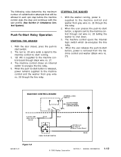
... wire no . 28 wire sends a signal to the machine control to start switch. 2. The red no . 27). STOPPING THE WASHER 1. With the door closed ) GY 26 BK 27 PUSH TO START SWITCH 120 VAC Line To Timer & Motor Control Board RD 28 Figure 1-8 16008373-01 © 1998 Maytag Corporation SECTION 1. Push-To-Start Relay Operation STARTING THE...
... wire no . 28 wire sends a signal to the machine control to start switch. 2. The red no . 27). STOPPING THE WASHER 1. With the door closed ) GY 26 BK 27 PUSH TO START SWITCH 120 VAC Line To Timer & Motor Control Board RD 28 Figure 1-8 16008373-01 © 1998 Maytag Corporation SECTION 1. Push-To-Start Relay Operation STARTING THE...
Service Manual
Page 23
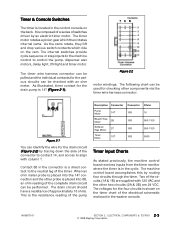
... ELECTRICAL COMPONENTS & TESTING 2 - 3 © 1998 Maytag Corporation Two of the complete drain circuit can identify the wire for checking other two circuits (2A & 2B) are 24 VDC. It is composed of a series of the pump Description Connector Connector Ohms Pump Motor 14T 10B...to align with column T. The voltages for the various circuits can be performed. The machine control board accomplishes this by tracing down the side of the electrical schematic enclosed in the washer console. 16008373-01 SECTION 2. The timer wire harness connector can be used for the ...
... ELECTRICAL COMPONENTS & TESTING 2 - 3 © 1998 Maytag Corporation Two of the complete drain circuit can identify the wire for checking other two circuits (2A & 2B) are 24 VDC. It is composed of a series of the pump Description Connector Connector Ohms Pump Motor 14T 10B...to align with column T. The voltages for the various circuits can be performed. The machine control board accomplishes this by tracing down the side of the electrical schematic enclosed in the washer console. 16008373-01 SECTION 2. The timer wire harness connector can be used for the ...
Service Manual
Page 24
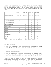
...washer to progress through several increments where the timer inputs normally do not change for 30 seconds, which the machine control will shut the cycle down if the timer does not advance. - The timer is solely used as an off-board set of relay switches. ELECTRICAL COMPONENTS & TESTING 2 - 4 © 1998 Maytag... Corporation During Main Wash: If the timer inputs do not change . 16008373-01 SECTION 2. Software in the machine control board specifically monitors the timer ...
...washer to progress through several increments where the timer inputs normally do not change for 30 seconds, which the machine control will shut the cycle down if the timer does not advance. - The timer is solely used as an off-board set of relay switches. ELECTRICAL COMPONENTS & TESTING 2 - 4 © 1998 Maytag... Corporation During Main Wash: If the timer inputs do not change . 16008373-01 SECTION 2. Software in the machine control board specifically monitors the timer ...
Service Manual
Page 25
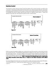
...for the various terminals on the microprocessor board. This will activate the L1 relay board and apply power on the console. ELECTRICAL COMPONENTS & TESTING 2 - 5 © 1998 Maytag Corporation The board receives input from the board, turn timer dial to facilitate the ...Connector Comm (Black wire). Machine Control The machine control microprocessor board is located in the control console, mounted to Series 17 Figure 2-3 Series 17 and After Figure 2-3b Both incoming and exiting voltage are monitored through the machine control board and the surrounding circuitry. To ...
...for the various terminals on the microprocessor board. This will activate the L1 relay board and apply power on the console. ELECTRICAL COMPONENTS & TESTING 2 - 5 © 1998 Maytag Corporation The board receives input from the board, turn timer dial to facilitate the ...Connector Comm (Black wire). Machine Control The machine control microprocessor board is located in the control console, mounted to Series 17 Figure 2-3 Series 17 and After Figure 2-3b Both incoming and exiting voltage are monitored through the machine control board and the surrounding circuitry. To ...
Service Manual
Page 27
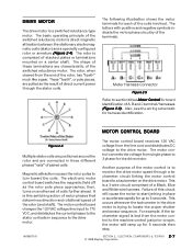
..., has "teeth" much like a gear. ELECTRICAL COMPONENTS & TESTING 2 - 7 © 1998 Maytag Corporation The rotor, when viewed from single phase to 3 phase for board identification of the switched reluctance motor. DRIVE MOTOR The drive motor is to monitor the drive motor speed.... The following illustration shows the motor terminals for harness identification. Also, see the wiring schematic for each of the terminals. MOTOR CONTROL BOARD Figure 2-4 Multiple stator coils are positioned around the rotor and are characteristic of A, B and C terminal/harnesses (Figure 2-6). then...
..., has "teeth" much like a gear. ELECTRICAL COMPONENTS & TESTING 2 - 7 © 1998 Maytag Corporation The rotor, when viewed from single phase to 3 phase for board identification of the switched reluctance motor. DRIVE MOTOR The drive motor is to monitor the drive motor speed.... The following illustration shows the motor terminals for harness identification. Also, see the wiring schematic for each of the terminals. MOTOR CONTROL BOARD Figure 2-4 Multiple stator coils are positioned around the rotor and are characteristic of A, B and C terminal/harnesses (Figure 2-6). then...
Service Manual
Page 28
... the 10-amp fuse located on the motor control board. If fuse and semiconductors show no . 13) on the control board, either visually or with a large load (See Section 3: Troubleshooting). 16008373-01 SECTION 2. This could result in the delay mode. ELECTRICAL COMPONENTS & TESTING 2 - 8 © 1998 Maytag Corporation Unplug the washer power cord. If bad, completely replace motor...
... the 10-amp fuse located on the motor control board. If fuse and semiconductors show no . 13) on the control board, either visually or with a large load (See Section 3: Troubleshooting). 16008373-01 SECTION 2. This could result in the delay mode. ELECTRICAL COMPONENTS & TESTING 2 - 8 © 1998 Maytag Corporation Unplug the washer power cord. If bad, completely replace motor...
Service Manual
Page 29
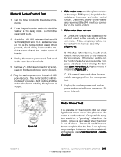
... from the motor control and perform an ohm check of the washer. 5. Each wire pair should be no continuity between the motor control board and the base. 6 . Reassemble the drip shield cover onto the motor control. 8. ELECTRICAL COMPONENTS & TESTING © 1998 Maytag Corporation 2-9 Unsnap ... and neutral wires. Disconnect power to testing. 2 . Plug the power cord into the washer when finished. Carefully lift the front end of the motor control board. Reposition the motor control into the wall socket and press the push-to disengage the rear locking tabs from the...
... from the motor control and perform an ohm check of the washer. 5. Each wire pair should be no continuity between the motor control board and the base. 6 . Reassemble the drip shield cover onto the motor control. 8. ELECTRICAL COMPONENTS & TESTING © 1998 Maytag Corporation 2-9 Unsnap ... and neutral wires. Disconnect power to testing. 2 . Plug the power cord into the washer when finished. Carefully lift the front end of the motor control board. Reposition the motor control into the wall socket and press the push-to disengage the rear locking tabs from the...
Service Manual
Page 30
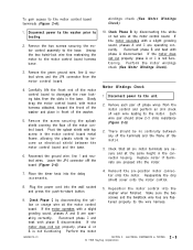
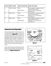
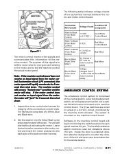
..." pass through the sensor field, signals are repeated eight times. The pattern consists of six different "pickets" which are generated and transmitted to the motor control board through the tachometer wire harness (Figure 2-10 and 2-11). PHASE WIRE COLORS C Yellow or Orange B White or Red A Black or Blue MOTOR CONDITION RESULT/SOLUTION...of the motor shaft under the plastic endbell covering of the shutter resembles a "picket fence" with different size "pickets." ELECTRICAL COMPONENTS & TESTING 2-10 © 1998 Maytag Corporation Figure 2-9 16008373-01 Figure 2-10 SECTION 2.
..." pass through the sensor field, signals are repeated eight times. The pattern consists of six different "pickets" which are generated and transmitted to the motor control board through the tachometer wire harness (Figure 2-10 and 2-11). PHASE WIRE COLORS C Yellow or Orange B White or Red A Black or Blue MOTOR CONDITION RESULT/SOLUTION...of the motor shaft under the plastic endbell covering of the shutter resembles a "picket fence" with different size "pickets." ELECTRICAL COMPONENTS & TESTING 2-10 © 1998 Maytag Corporation Figure 2-9 16008373-01 Figure 2-10 SECTION 2.
Service Manual
Page 31
... washer into the back side of the tachommeter harness. The following table indicates voltage checks of the connections on the motor control and insert the meter probes into the Delay Wash cycle and press the start without activating the motor. Note: If the machine control board ...for integrity of the tachometer harness between the motor and motor control board. Tachometer Wire Checks Voltage Found Condition Of Component White to the machine control. The purpose of a White, Blue and Black wire. 2. Inspect the motor control wire harness for 5 seconds then shut down . 1. Leave...
... washer into the back side of the tachommeter harness. The following table indicates voltage checks of the connections on the motor control and insert the meter probes into the Delay Wash cycle and press the start without activating the motor. Note: If the machine control board ...for integrity of the tachometer harness between the motor and motor control board. Tachometer Wire Checks Voltage Found Condition Of Component White to the machine control. The purpose of a White, Blue and Black wire. 2. Inspect the motor control wire harness for 5 seconds then shut down . 1. Leave...
Service Manual
Page 33
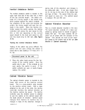
...front of the switch may prove difficult. Testing the Inertial Unbalance Switch: Testing of the top concrete weight. The switch will open unless the switch is a piezo-electric strip mounted to the unit. 2 . Disconnect power to the machine control board... © 1998 Maytag Corporation 2-13 The mass vibrates 180 degrees out of phase with the least amount of a mass suspended by the clothes load at 800 rpm ...side to the end of the machine control board. The machine controller uses the vibration sensor to attempt to spin the washer at approximately 800 rpm. changes in the...
...front of the switch may prove difficult. Testing the Inertial Unbalance Switch: Testing of the top concrete weight. The switch will open unless the switch is a piezo-electric strip mounted to the unit. 2 . Disconnect power to the machine control board... © 1998 Maytag Corporation 2-13 The mass vibrates 180 degrees out of phase with the least amount of a mass suspended by the clothes load at 800 rpm ...side to the end of the machine control board. The machine controller uses the vibration sensor to attempt to spin the washer at approximately 800 rpm. changes in the...
Service Manual
Page 35
... between motor, the motor control board and the machine control board. Shuts OFF During Final Rinses: The machine control board is locked. Check the incoming water lines for poor connections at the timer and the machine control board. If lower, the customer can use smaller clothes loads and reduce the pressure to metal screened washers and remove the nozzle extender...
... between motor, the motor control board and the machine control board. Shuts OFF During Final Rinses: The machine control board is locked. Check the incoming water lines for poor connections at the timer and the machine control board. If lower, the customer can use smaller clothes loads and reduce the pressure to metal screened washers and remove the nozzle extender...
Service Manual
Page 36
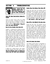
...RD23. Replace the door lock mechanism. Machine Operation Does Not Match Cycle Description: The machine control board monitors where the timer is activated during an unbalanced load condition. At the end of rinses through the wash cycle. Also, check wiring of ...Maytag Corporation SECTION 3. Check the connections of cabinet to determine if vibration noise due to the machine control board inform the machine control board where the timer is locked. This ensures the door is stuck. Place hand on the door lock enable switch in the wash cycle. Four input wires from the washer...
...RD23. Replace the door lock mechanism. Machine Operation Does Not Match Cycle Description: The machine control board monitors where the timer is activated during an unbalanced load condition. At the end of rinses through the wash cycle. Also, check wiring of ...Maytag Corporation SECTION 3. Check the connections of cabinet to determine if vibration noise due to the machine control board inform the machine control board where the timer is locked. This ensures the door is stuck. Place hand on the door lock enable switch in the wash cycle. Four input wires from the washer...
Service Manual
Page 37
... Water Carrying Components). The wax motors are loose. 16008373-01 © 1998 Maytag Corporation SECTION 3. Note: If the timer motor is not correct, suspect a...front weight mounting bolts or a loose bolt securing the driven pulley. "Ticking or Knocking" Noise In Spin: The noise could be interfering with the driven pulley. If the timing is energized for five minutes without the cycle inputs changing, the machine control board... will drop the line voltage relay. Did the timer advance to the washer shutting down too soon or ...
... Water Carrying Components). The wax motors are loose. 16008373-01 © 1998 Maytag Corporation SECTION 3. Note: If the timer motor is not correct, suspect a...front weight mounting bolts or a loose bolt securing the driven pulley. "Ticking or Knocking" Noise In Spin: The noise could be interfering with the driven pulley. If the timing is energized for five minutes without the cycle inputs changing, the machine control board... will drop the line voltage relay. Did the timer advance to the washer shutting down too soon or ...
Service Manual
Page 77
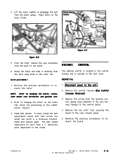
...the wire harness hookup to the control board. 4. Figure 8-3 Figure 8-2 5 . Check belt tension. MACHINE CONTROL The machine control is secured to hanging the motor on the base frame. Remove the wiring from the motor pulley. MOTOR DRIVE SYSYTEM © 1998 Maytag Corporation 8-2 4 . Grasp ... Remove the two 5/16" nuts securing the board to remount the board. 16008373-01 SECTION 8. Place motor on the outer tub, check the positioning of the motor. 6 . Remove the control console (See Control Console Removal). 3 . From the front, remove the wire harnesses from the pivot hang...
...the wire harness hookup to the control board. 4. Figure 8-3 Figure 8-2 5 . Check belt tension. MACHINE CONTROL The machine control is secured to hanging the motor on the base frame. Remove the wiring from the motor pulley. MOTOR DRIVE SYSYTEM © 1998 Maytag Corporation 8-2 4 . Grasp ... Remove the two 5/16" nuts securing the board to remount the board. 16008373-01 SECTION 8. Place motor on the outer tub, check the positioning of the motor. 6 . Remove the control console (See Control Console Removal). 3 . From the front, remove the wire harnesses from the pivot hang...
Service Manual
Page 78
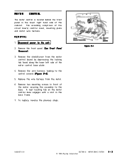
... © 1998 Maytag Corporation 8-3 Remove the shield/cover from the motor. 6 . Remove the wire harness from the motor control board by depressing the locking tab found along the lower left side of the motor securing the assembly to the base. Remove the front panel (See Front Panel Removal). 3... . A rear locating tab on the motor control base engages with a slot in...
... © 1998 Maytag Corporation 8-3 Remove the shield/cover from the motor. 6 . Remove the wire harness from the motor control board by depressing the locking tab found along the lower left side of the motor securing the assembly to the base. Remove the front panel (See Front Panel Removal). 3... . A rear locating tab on the motor control base engages with a slot in...
Service Manual
Page 89
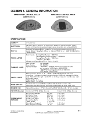
...varies with clothes load. Power cord must be 20 - 120 P.S.I. (1.06-8.44 kg/cm) at inlet hose connection. Motor Input: During Wash Tumble - 170 Watts During Rinse Tumble - 195 Watts Top Spin - 800 Watts (Wattage readings taken with inlet washers and attached ... Spinner RPM) 14 to water valve. Switched Reluctance Motor controlled by a microprocessor motor control board. Bolt, Counter Weight Bolt, Spin Pulley Bolt, Belt Adjuster Screw, Front Baffle Screw, Rear Baffle Clamp, Hoses Nuts, Spinner Support Nuts, Suspension struts 7 in . Cabinet Dimensions: 27" (68.58cm) W x 271/2" (69.85cm) ...
...varies with clothes load. Power cord must be 20 - 120 P.S.I. (1.06-8.44 kg/cm) at inlet hose connection. Motor Input: During Wash Tumble - 170 Watts During Rinse Tumble - 195 Watts Top Spin - 800 Watts (Wattage readings taken with inlet washers and attached ... Spinner RPM) 14 to water valve. Switched Reluctance Motor controlled by a microprocessor motor control board. Bolt, Counter Weight Bolt, Spin Pulley Bolt, Belt Adjuster Screw, Front Baffle Screw, Rear Baffle Clamp, Hoses Nuts, Spinner Support Nuts, Suspension struts 7 in . Cabinet Dimensions: 27" (68.58cm) W x 271/2" (69.85cm) ...
Service Manual
Page 95
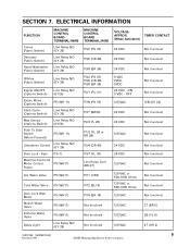
... Water Valve Delay Light P5 (WH11) P5 (WH11) P5 (WH11) Line Relay NO (GY 26) MACHINE CONTROL BOARD TERMINAL/WIRE P3/2 (PK 37) P3/6 (OR 38) P3/8 (BR 39) P3/2 (PK 37) P3...27) P7/1 (OR7) P7/2 (BU 9) P7/4 (BR 14) Not Involved Not Involved Not Involved VOLTAGEAPPROX. (When Activated) TIMER CONTACT 24 VDC Not Involved 24 VDC Not Involved 24 VDC 0 VDC 0VDC 0VDC 24 VDC - ON 0 VDC - ELECTRICAL INFORMATION FUNCTION Colors (Fabric Switch) Delicates (Fabric Switch) Hand Washables (Fabric Switch) MACHINE CONTROL BOARD...-03) 8 Revised 7/00 ©2000 Maytag Appliances Sales Company
... Water Valve Delay Light P5 (WH11) P5 (WH11) P5 (WH11) Line Relay NO (GY 26) MACHINE CONTROL BOARD TERMINAL/WIRE P3/2 (PK 37) P3/6 (OR 38) P3/8 (BR 39) P3/2 (PK 37) P3...27) P7/1 (OR7) P7/2 (BU 9) P7/4 (BR 14) Not Involved Not Involved Not Involved VOLTAGEAPPROX. (When Activated) TIMER CONTACT 24 VDC Not Involved 24 VDC Not Involved 24 VDC 0 VDC 0VDC 0VDC 24 VDC - ON 0 VDC - ELECTRICAL INFORMATION FUNCTION Colors (Fabric Switch) Delicates (Fabric Switch) Hand Washables (Fabric Switch) MACHINE CONTROL BOARD...-03) 8 Revised 7/00 ©2000 Maytag Appliances Sales Company
Service Manual
Page 109
... Bolt, Counter Weight Bolt, Spin Pulley Bolt, Belt Adjuster Screw, Front Baffle Screw, Rear Baffle Clamp, Hoses Nuts, Spinner Support Nuts, Suspension struts 7 ft. lbs. 25 in . lbs. 7 ft. lbs.) 16010486 (16008373-05) Revised 02/01 Section 1. Cabinet Dimensions: 27" (68.58cm) W x 271/2" (69.85cm) D x 36... controlled by a microprocessor motor control board. Total water usage is approximately 25 gallons, varies with clothes load. lbs. 15 + in spin.) Wash Tumble Rinse Tumble High Speed Spin 47 - 55 RPM 47 - 55 RPM 800 RPM (+ 50 RPM based upon optimum spin performance) LED Washer ...
... Bolt, Counter Weight Bolt, Spin Pulley Bolt, Belt Adjuster Screw, Front Baffle Screw, Rear Baffle Clamp, Hoses Nuts, Spinner Support Nuts, Suspension struts 7 ft. lbs. 25 in . lbs. 7 ft. lbs.) 16010486 (16008373-05) Revised 02/01 Section 1. Cabinet Dimensions: 27" (68.58cm) W x 271/2" (69.85cm) D x 36... controlled by a microprocessor motor control board. Total water usage is approximately 25 gallons, varies with clothes load. lbs. 15 + in spin.) Wash Tumble Rinse Tumble High Speed Spin 47 - 55 RPM 47 - 55 RPM 800 RPM (+ 50 RPM based upon optimum spin performance) LED Washer ...
Service Manual
Page 110
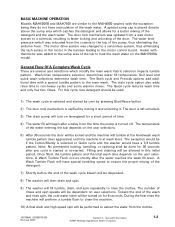
... machine. 10) A final drain and high speed spin will be performed to extract the water from the console to the motor control board. General Information ©2001 Maytag Appliances Sales Company 1-2 Heater with a special tumble pattern to a solenoid, resulting in this cycle, less detergent should be dependent ... the exception being they do not have recirculation of the wash cycle bleach will be dispensed. 8) The washer will then drain and spin. 9) The washer will fill tumble, drain, and spin repeatedly to heat the wash water on the user selections. 5) After 30 seconds the...
... machine. 10) A final drain and high speed spin will be performed to extract the water from the console to the motor control board. General Information ©2001 Maytag Appliances Sales Company 1-2 Heater with a special tumble pattern to a solenoid, resulting in this cycle, less detergent should be dependent ... the exception being they do not have recirculation of the wash cycle bleach will be dispensed. 8) The washer will then drain and spin. 9) The washer will fill tumble, drain, and spin repeatedly to heat the wash water on the user selections. 5) After 30 seconds the...


