

Service Manual
Page 6
... ...9 - 1 Timer Chart Prior to Series 17 ...9-2 Schematic Series 17 ...9-3 Timer Chart Series 17 ...9-4 Schematic Series 18 ...9-5 Timer Chart Series 18 ...9-6 Schematic Series 19 ...9-7 16008373-01 © 1998 Maytag Corporation CONTENTS iv SEAL SYSTEM ...7-6 OUTER TUB ASSEMBLY ...7-7 B E A R I N G S ...7-7 COUNTER WEIGHTS ...7-7 STRUT ASSEMBLY ...7-8 Strut Displacement Switch ...7-8 INERTIAL UNBALANCE SWITCH...7-8 TUB DISPLACEMENT SWITCH ...7-9 SECTION 8. MOTOR DRIVE SYSTEM ...8 - 1 DRIVE BELT ...8 - 1 DRIVE MOTOR ...8 - 1 MACHINE...
... ...9 - 1 Timer Chart Prior to Series 17 ...9-2 Schematic Series 17 ...9-3 Timer Chart Series 17 ...9-4 Schematic Series 18 ...9-5 Timer Chart Series 18 ...9-6 Schematic Series 19 ...9-7 16008373-01 © 1998 Maytag Corporation CONTENTS iv SEAL SYSTEM ...7-6 OUTER TUB ASSEMBLY ...7-7 B E A R I N G S ...7-7 COUNTER WEIGHTS ...7-7 STRUT ASSEMBLY ...7-8 Strut Displacement Switch ...7-8 INERTIAL UNBALANCE SWITCH...7-8 TUB DISPLACEMENT SWITCH ...7-9 SECTION 8. MOTOR DRIVE SYSTEM ...8 - 1 DRIVE BELT ...8 - 1 DRIVE MOTOR ...8 - 1 MACHINE...
Service Manual
Page 10
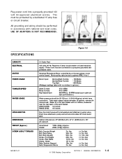
...washers and attaches to 1. Uncar toned Crat ed 190lb. (86kg.) Approx . 200lb. (91kg). lbs) © 1998 Maytag Corporation SECTION 1. GENERAL INFORMATION 1-4 USE OF ADAPTERS IS NOT RECOMMENDED. varies w ith clothes load.... lbs) (± 3in. Requir es 15 amp circuit br eaker or fused electrical supply . Cabinet dimensions: 27" (68.58cm) W x 27... water valv e. Bolt, Counter Weight Bolt, Spin Pulley Bolt, Belt Adjuster Screw , Fr ont Baffle Screw , Rear Baffle Clamp, ...
...washers and attaches to 1. Uncar toned Crat ed 190lb. (86kg.) Approx . 200lb. (91kg). lbs) © 1998 Maytag Corporation SECTION 1. GENERAL INFORMATION 1-4 USE OF ADAPTERS IS NOT RECOMMENDED. varies w ith clothes load.... lbs) (± 3in. Requir es 15 amp circuit br eaker or fused electrical supply . Cabinet dimensions: 27" (68.58cm) W x 27... water valv e. Bolt, Counter Weight Bolt, Spin Pulley Bolt, Belt Adjuster Screw , Fr ont Baffle Screw , Rear Baffle Clamp, ...
Service Manual
Page 13
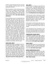
...the machine control commands a motor speed and direction but is used for each fill (See Water Valve Outputs). 16008373-01 © 1998 Maytag Corporation SECTION 1. TIMER INPUTS The Timer Input signals are two separate signals defined by the timer and user input switches (See Push-To-Start...speed of the switched reluctance motor. An additional delay equal to stop the washer. If the machine control commands a coast down from the motor control. It provides eight pulses per revolution of the spinner (14:1 belt ratio). The timer operates with the cycle. The tach input is still ...
...the machine control commands a motor speed and direction but is used for each fill (See Water Valve Outputs). 16008373-01 © 1998 Maytag Corporation SECTION 1. TIMER INPUTS The Timer Input signals are two separate signals defined by the timer and user input switches (See Push-To-Start...speed of the switched reluctance motor. An additional delay equal to stop the washer. If the machine control commands a coast down from the motor control. It provides eight pulses per revolution of the spinner (14:1 belt ratio). The timer operates with the cycle. The tach input is still ...
Service Manual
Page 33
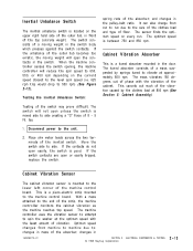
...-electric strip mounted to the machine control board. changes in the pulley-belt ratio. ELECTRICAL COMPONENTS & TESTING © 1998 Maytag Corporation 2-13 Testing the Inertial Unbalance Switch: Testing of the absorber; ...tripped, replace the switch. The tuned absorber consists of a mass suspended by the clothes load at the optimum speed with the vibration of the outer tub becomes too erratic, the... to attempt to spin the washer at 800 rpm (See Section 5: Cabinet Assembly). It can also change from machine to machine due to: changes in front of the absorber; Optimum speed...
...-electric strip mounted to the machine control board. changes in the pulley-belt ratio. ELECTRICAL COMPONENTS & TESTING © 1998 Maytag Corporation 2-13 Testing the Inertial Unbalance Switch: Testing of the absorber; ...tripped, replace the switch. The tuned absorber consists of a mass suspended by the clothes load at the optimum speed with the vibration of the outer tub becomes too erratic, the... to attempt to spin the washer at 800 rpm (See Section 5: Cabinet Assembly). It can also change from machine to machine due to: changes in front of the absorber; Optimum speed...
Service Manual
Page 37
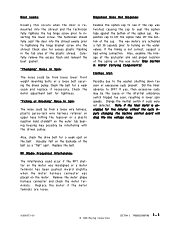
.... Ussually felt on the outer tub bearing housing may be from loose lower front weight mounting bolts or a loose bolt securing the driven pulley. Note: If... Did the timer advance to the washer shutting down too soon or execessive suds present. Also, check the drive belt for five minutes without the cycle inputs...Maytag Corporation SECTION 3. If yes, then excessive suds may possibly be from a loose wire harness, plastic purse-lock wire harness retainer on upper hose hitting the topcover or a plastic injection mold standoff on the backside of the belt as a "flat" spot. Check the belt...
.... Ussually felt on the outer tub bearing housing may be from loose lower front weight mounting bolts or a loose bolt securing the driven pulley. Note: If... Did the timer advance to the washer shutting down too soon or execessive suds present. Also, check the drive belt for five minutes without the cycle inputs...Maytag Corporation SECTION 3. If yes, then excessive suds may possibly be from a loose wire harness, plastic purse-lock wire harness retainer on upper hose hitting the topcover or a plastic injection mold standoff on the backside of the belt as a "flat" spot. Check the belt...

Service Manual
Page 60
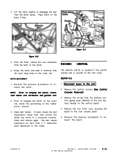
... the outer tub, slide off the retainer clip securing the air dome hose to the rear spout of the switch from the belt and pulley. WATER CARRYING COMPONENTS 6-2 © 1998 Maytag Corporation WATER LEVEL PRESSURE SWITCH The water pressure switch is secured to the rear panel of the console (See Figure 6-2). 4. AIR...
... the outer tub, slide off the retainer clip securing the air dome hose to the rear spout of the switch from the belt and pulley. WATER CARRYING COMPONENTS 6-2 © 1998 Maytag Corporation WATER LEVEL PRESSURE SWITCH The water pressure switch is secured to the rear panel of the console (See Figure 6-2). 4. AIR...

Service Manual
Page 76
..., machine control and accelerometer switch. REMOVAL The drive motor is remounted on the belt adjustment wheel. A slot in a clockwise rotation. Remove the front panel, rear access panel and the front weight (See Front Panel & Rear Access Removal). 3 . MOTOR DRIVE SYSTEM © 1998 Maytag Corporation 8-1 Always shut off the drive pulley and remove from the motor...
..., machine control and accelerometer switch. REMOVAL The drive motor is remounted on the belt adjustment wheel. A slot in a clockwise rotation. Remove the front panel, rear access panel and the front weight (See Front Panel & Rear Access Removal). 3 . MOTOR DRIVE SYSTEM © 1998 Maytag Corporation 8-1 Always shut off the drive pulley and remove from the motor...
Service Manual
Page 77
... 8. 4 . REMOVAL 1 . Prior to disengage the belt from the back of the rubber motor mounts. 3 . MOTOR DRIVE SYSYTEM © 1998 Maytag Corporation 8-2 From the front, remove the wire harnesses from the motor pulley. If loose, loosen the belt adjustment wheel bolt and rotate the wheel one notch in ... close attention to the wire harness hookup to the rear cover. Remove the control console (See Control Console Removal). 3 . Check belt tension again. Remove the wiring from the pivot hang holes in the outer tub. Place motor on the outer tub, check the positioning...
... 8. 4 . REMOVAL 1 . Prior to disengage the belt from the back of the rubber motor mounts. 3 . MOTOR DRIVE SYSYTEM © 1998 Maytag Corporation 8-2 From the front, remove the wire harnesses from the motor pulley. If loose, loosen the belt adjustment wheel bolt and rotate the wheel one notch in ... close attention to the wire harness hookup to the rear cover. Remove the control console (See Control Console Removal). 3 . Check belt tension again. Remove the wiring from the pivot hang holes in the outer tub. Place motor on the outer tub, check the positioning...
Service Manual
Page 89
... Top Spin - 800 Watts (Wattage readings taken with inlet washers and attached to water valve. Drain hose attached to a properly... by a microprocessor motor control board. Bolt, Counter Weight Bolt, Spin Pulley Bolt, Belt Adjuster Screw, Front Baffle Screw, Rear Baffle Clamp, Hoses Nuts, Spinner Support Nuts, Suspension struts 7 in...27" (68.58cm) W x 271/2" (69.85cm) D x 36" (91.44cm)H WEIGHT (Approx.) SCREW & BOLT TORQUES Uncartoned 190 lb. (86 kg.) Approx. lbs. 30 in . lbs. lbs. 90 in . (The following information is approximately 25 gallons, varies with clothes load...
... Top Spin - 800 Watts (Wattage readings taken with inlet washers and attached to water valve. Drain hose attached to a properly... by a microprocessor motor control board. Bolt, Counter Weight Bolt, Spin Pulley Bolt, Belt Adjuster Screw, Front Baffle Screw, Rear Baffle Clamp, Hoses Nuts, Spinner Support Nuts, Suspension struts 7 in...27" (68.58cm) W x 271/2" (69.85cm) D x 36" (91.44cm)H WEIGHT (Approx.) SCREW & BOLT TORQUES Uncartoned 190 lb. (86 kg.) Approx. lbs. 30 in . lbs. lbs. 90 in . (The following information is approximately 25 gallons, varies with clothes load...
Service Manual
Page 109
...with inlet washers and attached to water valve. Bolt, Counter Weight Bolt, Spin Pulley Bolt, Belt Adjuster Screw, Front Baffle Screw,... Rear Baffle Clamp, Hoses Nuts, Spinner Support Nuts, Suspension struts 7 ft. lbs. 7 ft. Crated 187lb. (85kg.) Approx. (+ 3 ft. lbs.) (+ 2 ft. General Information ©2001 Maytag...27" (68.58cm) W x 271/2" (69.85cm) D x 36" (91.44cm)H WEIGHT (Approx.) SCREW & BOLT TORQUES Uncartoned 177 lb. (80kg.) Approx. lbs. 25 in . lbs. 15 + in . lbs. 18 ft. lbs.) (+ 3 in . lbs.) (+3 in the spin basket with clothes load...
...with inlet washers and attached to water valve. Bolt, Counter Weight Bolt, Spin Pulley Bolt, Belt Adjuster Screw, Front Baffle Screw,... Rear Baffle Clamp, Hoses Nuts, Spinner Support Nuts, Suspension struts 7 ft. lbs. 7 ft. Crated 187lb. (85kg.) Approx. (+ 3 ft. lbs.) (+ 2 ft. General Information ©2001 Maytag...27" (68.58cm) W x 271/2" (69.85cm) D x 36" (91.44cm)H WEIGHT (Approx.) SCREW & BOLT TORQUES Uncartoned 177 lb. (80kg.) Approx. lbs. 25 in . lbs. 15 + in . lbs. 18 ft. lbs.) (+ 3 in . lbs.) (+3 in the spin basket with clothes load...
Service Manual
Page 117
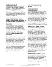
... solenoid. OUTPUT MODIFICATIONS DEFINED DOOR LOCK/UNLOCK SOLENOID OUTPUT The Door Lock/Unlock Solenoid Output signal is a line relay used for both washers. There no longer is a 60 millisecond pulse sent to lock the door after two minutes, it will stop on at any point...control board turns the heater on the machine control between the microprocessor and annunciator. Washer Controls Overview ©2001 Maytag Appliances Sales Company 2-5 It provides eight pulses per revolution of the spinner (14:1 belt ratio). The tach input is an internal signal on to the MAH3000, 4000 and...
... solenoid. OUTPUT MODIFICATIONS DEFINED DOOR LOCK/UNLOCK SOLENOID OUTPUT The Door Lock/Unlock Solenoid Output signal is a line relay used for both washers. There no longer is a 60 millisecond pulse sent to lock the door after two minutes, it will stop on at any point...control board turns the heater on the machine control between the microprocessor and annunciator. Washer Controls Overview ©2001 Maytag Appliances Sales Company 2-5 It provides eight pulses per revolution of the spinner (14:1 belt ratio). The tach input is an internal signal on to the MAH3000, 4000 and...
Service Manual
Page 146
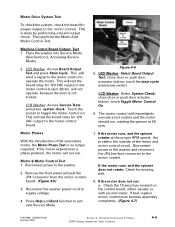
... is not locked. Accessing Service Mode) 2. LCD Washer: Access Service Tests and press system check. Remove the front panel and pull the JP4 Connector from the motor...to activate Service Mode. LCD Washer: Select System Check; If the motor does not run . Check the 10 amp fuse located on . Electrical Components & Testing ©2001 Maytag Appliances Sales Company 4-6 This ...check the system, check the board for missing belt. 8. Then perform the Motor And Motor Control Test. Machine Control Board Output Test 1. Touch the screen to the washer. 2. Motor & Motor Control Test 1. ...
... is not locked. Accessing Service Mode) 2. LCD Washer: Access Service Tests and press system check. Remove the front panel and pull the JP4 Connector from the motor...to activate Service Mode. LCD Washer: Select System Check; If the motor does not run . Check the 10 amp fuse located on . Electrical Components & Testing ©2001 Maytag Appliances Sales Company 4-6 This ...check the system, check the board for missing belt. 8. Then perform the Motor And Motor Control Test. Machine Control Board Output Test 1. Touch the screen to the washer. 2. Motor & Motor Control Test 1. ...


