

Service Manual
Page 53
... screw of the front panel in the front shroud. Remount the door into each hinge secured to the inner door plug. 16008373-01 © 1998 Maytag Corporation SECTION 5. The top edge of a steel plate suspended with one screw into the new slots and secure with springs. CABINET ASSEMBLY 5 - 1 CABINET ASSEMBLY Warning - DISASSEMBLY 1. DOOR ASSEMBLY...
... screw of the front panel in the front shroud. Remount the door into each hinge secured to the inner door plug. 16008373-01 © 1998 Maytag Corporation SECTION 5. The top edge of a steel plate suspended with one screw into the new slots and secure with springs. CABINET ASSEMBLY 5 - 1 CABINET ASSEMBLY Warning - DISASSEMBLY 1. DOOR ASSEMBLY...
Service Manual
Page 63
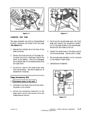
... © 1998 Maytag Corporation 6-5 Position the second pump near the first pump and connect the accessory connector to the sump intake of the pump housing from the existing pump in the washer. 3. Figure 6-6 CLEANING THE PUMP Figure 6-7 The pump assembly can also be disassembled without removing the ...to the drain outlet of the second pump. Depress the locking tab on the face of the washer. Rotate the block portion of the pump containing the motor windings toward the front of the pump housing. 2. Connect the drain hose to the pump drain outlet and secure with ...
... © 1998 Maytag Corporation 6-5 Position the second pump near the first pump and connect the accessory connector to the sump intake of the pump housing from the existing pump in the washer. 3. Figure 6-6 CLEANING THE PUMP Figure 6-7 The pump assembly can also be disassembled without removing the ...to the drain outlet of the second pump. Depress the locking tab on the face of the washer. Rotate the block portion of the pump containing the motor windings toward the front of the pump housing. 2. Connect the drain hose to the pump drain outlet and secure with ...


