
Service Manual
Page 4
... Test...2-2 Wax Motor Check/Door Lock Mechanism 2-2 Timer & Console Switches ...2-3 Timer Input Charts ...2-3 Machine Control...2-5 DRIVE MOTOR ...2-7 MOTOR CONTROL BOARD ...2-7 Motor & Motor Control Test ...2-8 Motor Phase Test ...2-8 Motor Windings Check ...2-9 Tachometer Circuit Diagnostics ...2-10 UNBALANCE CONTROL SYSTEM ...2 - 1 1 Tub Displacement Switch ...2 - 1 2 Strut Displacement Switch ...2 - 1 2 Inertial Unbalance Switch ...2 - 1 3 Cabinet Vibration Sensor ...2 - 1 3 Cabinet Vibration Absorber ...2 - 1 3 16008373-01 © 1998 Maytag Corporation CONTENTS...
... Test...2-2 Wax Motor Check/Door Lock Mechanism 2-2 Timer & Console Switches ...2-3 Timer Input Charts ...2-3 Machine Control...2-5 DRIVE MOTOR ...2-7 MOTOR CONTROL BOARD ...2-7 Motor & Motor Control Test ...2-8 Motor Phase Test ...2-8 Motor Windings Check ...2-9 Tachometer Circuit Diagnostics ...2-10 UNBALANCE CONTROL SYSTEM ...2 - 1 1 Tub Displacement Switch ...2 - 1 2 Strut Displacement Switch ...2 - 1 2 Inertial Unbalance Switch ...2 - 1 3 Cabinet Vibration Sensor ...2 - 1 3 Cabinet Vibration Absorber ...2 - 1 3 16008373-01 © 1998 Maytag Corporation CONTENTS...
Service Manual
Page 11
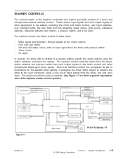
Door lock wax motor. - In general, the timer dial is complete. (See Figure 1-7 & 1-8 for the specific timer setting, it energizes the timer motor output to advance the timer to the next increment, reads a new set of the Neptune washer control system.) Figure 1-7 16008373-01 Prior To Series 17 © 1998 Maytag Corporation SECTION 1. When the machine control has...
Door lock wax motor. - In general, the timer dial is complete. (See Figure 1-7 & 1-8 for the specific timer setting, it energizes the timer motor output to advance the timer to the next increment, reads a new set of the Neptune washer control system.) Figure 1-7 16008373-01 Prior To Series 17 © 1998 Maytag Corporation SECTION 1. When the machine control has...
Service Manual
Page 13
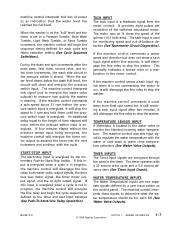
... will disengage the line relay, both water valve output signals, the door lock wax motor signal, the timer motor output signal, and the on the control panel. The machine control interprets this ... temperature should be for each fill (See Water Valve Outputs). 16008373-01 © 1998 Maytag Corporation SECTION 1. WATER TEMPERATURE INPUTS The Water Temperature inputs are energized through the cams in...a tach input signal within five seconds, it will disengage the line relay to stop the washer. The timer operates with the warm or cold wash or warm rinse temperature selections (See ...
... will disengage the line relay, both water valve output signals, the door lock wax motor signal, the timer motor output signal, and the on the control panel. The machine control interprets this ... temperature should be for each fill (See Water Valve Outputs). 16008373-01 © 1998 Maytag Corporation SECTION 1. WATER TEMPERATURE INPUTS The Water Temperature inputs are energized through the cams in...a tach input signal within five seconds, it will disengage the line relay to stop the washer. The timer operates with the warm or cold wash or warm rinse temperature selections (See ...
Service Manual
Page 14
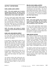
... "Door Locked" lights on washers from Series 17 and after are controlled by water level. END-OF-CYCLE SIGNAL OUTPUT The End-Of-Cycle Signal Output is operating in a wash or spin cycle. DOOR LOCK WAX MOTOR OUTPUT The Door Lock Wax Motor Output signal powers a wax motor in a 0.35 seconds on...allow for three minutes before the washer begins to coast from the final speed. 16008373-01 © 1998 Maytag Corporation SECTION 1. The end-of the cycle. If the washer is energized. ON LIGHT OUTPUT NOTE: This section applies only to washers between Series 10 and 16 are controlled ...
... "Door Locked" lights on washers from Series 17 and after are controlled by water level. END-OF-CYCLE SIGNAL OUTPUT The End-Of-Cycle Signal Output is operating in a wash or spin cycle. DOOR LOCK WAX MOTOR OUTPUT The Door Lock Wax Motor Output signal powers a wax motor in a 0.35 seconds on...allow for three minutes before the washer begins to coast from the final speed. 16008373-01 © 1998 Maytag Corporation SECTION 1. The end-of the cycle. If the washer is energized. ON LIGHT OUTPUT NOTE: This section applies only to washers between Series 10 and 16 are controlled ...
Service Manual
Page 16
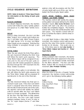
... timing of the final spin. Hand Washables 3 sec. - 27 sec. 16008373-01 © 1998 Maytag Corporation SECTION 1. D E L AY During a Delay increment, the door Lock Wax Motor Output, Door Locked Light Output (Series 17 and later only), Motor Torque Output, "On" light (Series 10 to fully retract. EXTRA RINSE When the user selects the...prior to the end of each pause. This allows time for the Door Lock Wax Motor to 16 only), and Water Valve Outputs are de-energized. Easy Care/Perm Press 6 sec. - 24 sec. washers only) will de-energize and the Endof-Cycle Signal will de-energize the line...
... timing of the final spin. Hand Washables 3 sec. - 27 sec. 16008373-01 © 1998 Maytag Corporation SECTION 1. D E L AY During a Delay increment, the door Lock Wax Motor Output, Door Locked Light Output (Series 17 and later only), Motor Torque Output, "On" light (Series 10 to fully retract. EXTRA RINSE When the user selects the...prior to the end of each pause. This allows time for the Door Lock Wax Motor to 16 only), and Water Valve Outputs are de-energized. Easy Care/Perm Press 6 sec. - 24 sec. washers only) will de-energize and the Endof-Cycle Signal will de-energize the line...
Service Manual
Page 17
...169; 1998 Maytag Corporation SECTION 1. At the start . Redistribution The machine control commands a distribution profile speed ramp from Series 17 and Later The machine control will allow the washer to lock ...the clothing load before resuming the spin. In a Prewash Tumble increment, the machine control will de-energize the line relay if the washer continues to stall (See Section 1: Timer Motor Output and...increment, the machine control will keep the door lock wax motor circuit energized until the timer inputs change so the washer can be run before the machine control will restart...
...169; 1998 Maytag Corporation SECTION 1. At the start . Redistribution The machine control commands a distribution profile speed ramp from Series 17 and Later The machine control will allow the washer to lock ...the clothing load before resuming the spin. In a Prewash Tumble increment, the machine control will de-energize the line relay if the washer continues to stall (See Section 1: Timer Motor Output and...increment, the machine control will keep the door lock wax motor circuit energized until the timer inputs change so the washer can be run before the machine control will restart...
Service Manual
Page 22
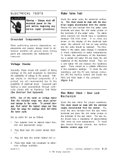
...of electrical shock. Remove the wire harness from the washer. To check the ohm resistance, pull the P2 wire harness connector off electrical power to water temperatures. To check wax motors through continuity checks with the electrical supply disconnected from the...see section: Machine Control page 2-5. 3. Wax Motor Check - Plug red lead into receptacle to the product. ELECTRICAL COMPONENTS & TESTING © 1998 Maytag Corporation 2-2 There should be replaced. Remove the wire harness from the washer. The wax motor should be made with an Appliance Test ...
...of electrical shock. Remove the wire harness from the washer. To check the ohm resistance, pull the P2 wire harness connector off electrical power to water temperatures. To check wax motors through continuity checks with the electrical supply disconnected from the...see section: Machine Control page 2-5. 3. Wax Motor Check - Plug red lead into receptacle to the product. ELECTRICAL COMPONENTS & TESTING © 1998 Maytag Corporation 2-2 There should be replaced. Remove the wire harness from the washer. The wax motor should be made with an Appliance Test ...
Service Manual
Page 23
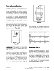
... 10B 18 Bleach Wax Motor 2B 10B 950-1100 Softener Wax Motor 2T 10B 950-1100 Timer Motor 10T 10B 5000 Timer Input Charts As stated previously, the machine control board receives inputs from the timer monitor where the timer is in the control console on the back. ELECTRICAL COMPONENTS & TESTING 2 - 3 © 1998 Maytag Corporation The...
... 10B 18 Bleach Wax Motor 2B 10B 950-1100 Softener Wax Motor 2T 10B 950-1100 Timer Motor 10T 10B 5000 Timer Input Charts As stated previously, the machine control board receives inputs from the timer monitor where the timer is in the control console on the back. ELECTRICAL COMPONENTS & TESTING 2 - 3 © 1998 Maytag Corporation The...
Service Manual
Page 35
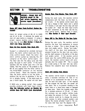
...complete door lock mechanism. If lower, the customer can use smaller clothes loads and reduce the pressure to the unit before beginning any service repair procedures...a minimum pressure of BK 27 to ensure the door is caused by a weak spring in the door lock wax motor. If the machine control ...washer goes into the delay cycle and then press the push to NO. If the required fill time exceeds the time limit, the washer will shut off . When the machine control tells the motor control to prevent flooding in the water valve inlet hose near the dispener inlet. 16008373-01 © 1998 Maytag...
...complete door lock mechanism. If lower, the customer can use smaller clothes loads and reduce the pressure to the unit before beginning any service repair procedures...a minimum pressure of BK 27 to ensure the door is caused by a weak spring in the door lock wax motor. If the machine control ...washer goes into the delay cycle and then press the push to NO. If the required fill time exceeds the time limit, the washer will shut off . When the machine control tells the motor control to prevent flooding in the water valve inlet hose near the dispener inlet. 16008373-01 © 1998 Maytag...
Service Manual
Page 36
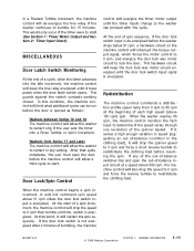
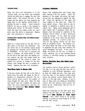
...the door is actually unlocked. If the circuit is stuck, the washer will not know when an unbalance occurs. The machine control board counts... wire to verify if the terminal is activated during an unbalanced load condition. Continuity should be cold regardless of the normally-closed switches... of 24 VDC and 120 VAC circuits. 16008373-01 © 1998 Maytag Corporation SECTION 3. If the door is unlocked and there is continuity, ... board monitors where the timer is in the "locked" mode, the wax motor has extended, forcing the latch axle to engage the door lock enable switch...
...the door is actually unlocked. If the circuit is stuck, the washer will not know when an unbalance occurs. The machine control board counts... wire to verify if the terminal is activated during an unbalanced load condition. Continuity should be cold regardless of the normally-closed switches... of 24 VDC and 120 VAC circuits. 16008373-01 © 1998 Maytag Corporation SECTION 3. If the door is unlocked and there is continuity, ... board monitors where the timer is in the "locked" mode, the wax motor has extended, forcing the latch axle to engage the door lock enable switch...
Service Manual
Page 37
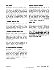
... hose hitting the topcover or a plastic injection mold standoff on the wax motor (See Section 6: Water Carrying Components). Examine the siphon cap to turning on the belt. The wax motors are loose. 16008373-01 © 1998 Maytag Corporation SECTION 3. Did the timer advance to inserting the lower screw... to tightening the hinge bracket screw into the shroud evenly prior to the washer shutting down too soon or execessive suds present. If yes, then excessive suds may possibly be from loose lower front weight mounting bolts or a loose bolt securing the driven pulley. "Ticking...
... hose hitting the topcover or a plastic injection mold standoff on the wax motor (See Section 6: Water Carrying Components). Examine the siphon cap to turning on the belt. The wax motors are loose. 16008373-01 © 1998 Maytag Corporation SECTION 3. Did the timer advance to inserting the lower screw... to tightening the hinge bracket screw into the shroud evenly prior to the washer shutting down too soon or execessive suds present. If yes, then excessive suds may possibly be from loose lower front weight mounting bolts or a loose bolt securing the driven pulley. "Ticking...

Service Manual
Page 55
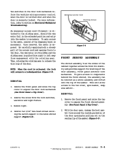
...Spring Gear Return Spring Accessory Cable Latch Axle Door Lock Switch Axle Spring Lamp Holder Door Switch Ramp Cover Latch Switch Holder Bulb © 1998 Maytag Corporation Figure 5-7 SECTION 5. This interlocking of teeth provides the locking action of the spin cycle, when tumbler speed drops below 90 RPM, ...cover and tilt the top cover toward the rear of the sliding gear will cool and relax the piston on the front shroud, open the door prior to the wax motor. When the proper water level is reached and the pressure switch is satisfied, 120 VAC is still positioned on ...
...Spring Gear Return Spring Accessory Cable Latch Axle Door Lock Switch Axle Spring Lamp Holder Door Switch Ramp Cover Latch Switch Holder Bulb © 1998 Maytag Corporation Figure 5-7 SECTION 5. This interlocking of teeth provides the locking action of the spin cycle, when tumbler speed drops below 90 RPM, ...cover and tilt the top cover toward the rear of the sliding gear will cool and relax the piston on the front shroud, open the door prior to the wax motor. When the proper water level is reached and the pressure switch is satisfied, 120 VAC is still positioned on ...
Service Manual
Page 56
... & Top Cover). 2. This will return to release the wire loop of the washer. REMOVAL 1. Once removed, the cable is necessary. By carefully applying both a steady pull of the gasket (Figure 5-9). 16008373-01 © 1998 Maytag Corporation SECTION 5. Thus, allowing the rotating gear to a locked position (Figure ...mounting of the door opening force to the door, the wax motor is overridden and the sliding gear is released, the lock will allow access to expose the front shroud assembly (See Front Panel & Top Cover). 2. Remove the front panel and raise the top cover to the tub cover...
... & Top Cover). 2. This will return to release the wire loop of the washer. REMOVAL 1. Once removed, the cable is necessary. By carefully applying both a steady pull of the gasket (Figure 5-9). 16008373-01 © 1998 Maytag Corporation SECTION 5. Thus, allowing the rotating gear to a locked position (Figure ...mounting of the door opening force to the door, the wax motor is overridden and the sliding gear is released, the lock will allow access to expose the front shroud assembly (See Front Panel & Top Cover). 2. Remove the front panel and raise the top cover to the tub cover...
Service Manual
Page 61
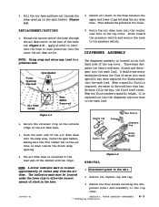
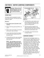
... mark must be located under the lower clip to the pressure switch. WATER CARRYING COMPONENTS © 1998 Maytag Corporation 6-3 Push the bent end of the air dome hose. A double wax motor mechanism directs the flow of the top cover. Three bays dispense the fabric softener, bleach and detergent into... in the top cover. Siphon Cup Rotary Nozzle REMOVAL Dispenser Bottom Figure 6-4 NOTE: A silver indicator mark is directed into the wash load. Thread the narrow end of slack in the left hand side of water into each specific bay when required for noise. DISPENSER ASSEMBLY NOTE...
... mark must be located under the lower clip to the pressure switch. WATER CARRYING COMPONENTS © 1998 Maytag Corporation 6-3 Push the bent end of the air dome hose. A double wax motor mechanism directs the flow of the top cover. Three bays dispense the fabric softener, bleach and detergent into... in the top cover. Siphon Cup Rotary Nozzle REMOVAL Dispenser Bottom Figure 6-4 NOTE: A silver indicator mark is directed into the wash load. Thread the narrow end of slack in the left hand side of water into each specific bay when required for noise. DISPENSER ASSEMBLY NOTE...
Service Manual
Page 95
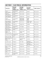
... Hot Water Valve P5 (WH11) Cold Water Valve P5 (WH11) Door Lock Wax Motor Bleach Water Valve Softener Water Valve Delay Light P5 (WH11) P5 (WH11) P5...YL 20) P1/3 (YL 28 or RD 28) P2/4 (OR 40) P3/7 (YL 36) Line Relay Com (BK 27) P7/1 (OR7) P7/2 (BU 9) P7/4 (BR 14) Not Involved Not Involved Not Involved VOLTAGEAPPROX. (When Activated) TIMER...120 VAC 2B (YL 6) 120 VAC 4T (OR 2) 16010199 (16008373-03) 8 Revised 7/00 ©2000 Maytag Appliances Sales Company ELECTRICAL INFORMATION FUNCTION Colors (Fabric Switch) Delicates (Fabric Switch) Hand Washables (Fabric Switch) MACHINE CONTROL...
... Hot Water Valve P5 (WH11) Cold Water Valve P5 (WH11) Door Lock Wax Motor Bleach Water Valve Softener Water Valve Delay Light P5 (WH11) P5 (WH11) P5...YL 20) P1/3 (YL 28 or RD 28) P2/4 (OR 40) P3/7 (YL 36) Line Relay Com (BK 27) P7/1 (OR7) P7/2 (BU 9) P7/4 (BR 14) Not Involved Not Involved Not Involved VOLTAGEAPPROX. (When Activated) TIMER...120 VAC 2B (YL 6) 120 VAC 4T (OR 2) 16010199 (16008373-03) 8 Revised 7/00 ©2000 Maytag Appliances Sales Company ELECTRICAL INFORMATION FUNCTION Colors (Fabric Switch) Delicates (Fabric Switch) Hand Washables (Fabric Switch) MACHINE CONTROL...
Service Manual
Page 96
Remove the front panel and lift the top cover. 3. The wax motor and linkage system designed for proper dispersing of the dispenser 3 gpm. Discontinue power and water to hold the valve in the valve mounting bracket. 2. ... a 4 coil water valve with the inlet hoses attached and direct the inlet hoses through the detergent wash area. 16010199 (16008373-03) 9 Revised 7/00 ©2000 Maytag Appliances Sales Company DISPENSER ASSEMBLY 5. NOTE: The mounting screw serves as a locating pin to the machine. 06&258(1:7,1* Figure 8-1 'HWHUJHQW :DVK 6. SECTION 8. WATER ...
Remove the front panel and lift the top cover. 3. The wax motor and linkage system designed for proper dispersing of the dispenser 3 gpm. Discontinue power and water to hold the valve in the valve mounting bracket. 2. ... a 4 coil water valve with the inlet hoses attached and direct the inlet hoses through the detergent wash area. 16010199 (16008373-03) 9 Revised 7/00 ©2000 Maytag Appliances Sales Company DISPENSER ASSEMBLY 5. NOTE: The mounting screw serves as a locating pin to the machine. 06&258(1:7,1* Figure 8-1 'HWHUJHQW :DVK 6. SECTION 8. WATER ...

Service Manual
Page 97
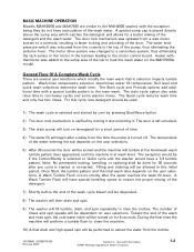
...previously used wax motor. Remove the front panel. 3. Lay a towel under the tub to disengage the locating tab of the mounting bracket from the front or the ...rear of the machine. DISPENSER FLUME DISPENSER BOTTOM DETERGENT WASH INLET HOSE RECIRCULATION PUMP The Recirculation Pump is accessible from the baseframe. (See Figure 8-5) Figure 8-3 NOZZLE WAS REMOVED 16010199 (16008373-03) 10 Revised 7/00 ©2000 Maytag... the pump connection to the siphon cup assembly. The pump is connected in series with the outer tub pump hose and the drain hose. (See Figure 8-4)...
...previously used wax motor. Remove the front panel. 3. Lay a towel under the tub to disengage the locating tab of the mounting bracket from the front or the ...rear of the machine. DISPENSER FLUME DISPENSER BOTTOM DETERGENT WASH INLET HOSE RECIRCULATION PUMP The Recirculation Pump is accessible from the baseframe. (See Figure 8-5) Figure 8-3 NOZZLE WAS REMOVED 16010199 (16008373-03) 10 Revised 7/00 ©2000 Maytag... the pump connection to the siphon cup assembly. The pump is connected in series with the outer tub pump hose and the drain hose. (See Figure 8-4)...
Service Manual
Page 110
... wash. The door lock mechanism was relocated from a wax motor system to extract the water from the time the pump is selected and started . Filling and draining will be dispensed. 8) The washer will then drain and spin. 9) The washer will be performed to a solenoid, resulting in this cycle...speeds will be locked and the machine will be allowed in faster locking and unlocking of the door. General Information ©2001 Maytag Appliances Sales Company 1-2 Soil level and quick wash selections determine wash time. The water level pressure switch was updated from the console...
... wash. The door lock mechanism was relocated from a wax motor system to extract the water from the time the pump is selected and started . Filling and draining will be dispensed. 8) The washer will then drain and spin. 9) The washer will be performed to a solenoid, resulting in this cycle...speeds will be locked and the machine will be allowed in faster locking and unlocking of the door. General Information ©2001 Maytag Appliances Sales Company 1-2 Soil level and quick wash selections determine wash time. The water level pressure switch was updated from the console...


