
Service Manual
Page 4
... 2-2 Timer & Console Switches ...2-3 Timer Input Charts ...2-3 Machine Control...2-5 DRIVE MOTOR ...2-7 MOTOR CONTROL BOARD ...2-7 Motor & Motor Control Test ...2-8 Motor Phase Test ...2-8 Motor Windings Check ...2-9 Tachometer Circuit Diagnostics ...2-10 UNBALANCE CONTROL SYSTEM ...2 - 1 1 Tub Displacement Switch ...2 - 1 2 Strut Displacement Switch ...2 - 1 2 Inertial Unbalance Switch ...2 - 1 3 Cabinet Vibration Sensor ...2 - 1 3 Cabinet Vibration Absorber ...2 - 1 3 16008373-01 © 1998 Maytag Corporation CONTENTS ii GENERAL INFORMATION ...1 - 1 PRE-INSTALLATION REQUIREMENTS...
... 2-2 Timer & Console Switches ...2-3 Timer Input Charts ...2-3 Machine Control...2-5 DRIVE MOTOR ...2-7 MOTOR CONTROL BOARD ...2-7 Motor & Motor Control Test ...2-8 Motor Phase Test ...2-8 Motor Windings Check ...2-9 Tachometer Circuit Diagnostics ...2-10 UNBALANCE CONTROL SYSTEM ...2 - 1 1 Tub Displacement Switch ...2 - 1 2 Strut Displacement Switch ...2 - 1 2 Inertial Unbalance Switch ...2 - 1 3 Cabinet Vibration Sensor ...2 - 1 3 Cabinet Vibration Absorber ...2 - 1 3 16008373-01 © 1998 Maytag Corporation CONTENTS ii GENERAL INFORMATION ...1 - 1 PRE-INSTALLATION REQUIREMENTS...
Service Manual
Page 18
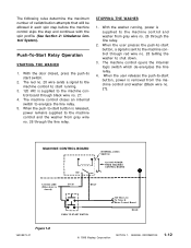
... releases the push-to the machine control and washer from the machine control and washer (Black wire no. 27). Push-To-Start Relay Operation STARTING THE WASHER 1. With the door closed ) GY 26 BK 27 PUSH TO START SWITCH 120 VAC Line To Timer & Motor Control Board RD 28 Figure 1-8 16008373-01 © 1998 Maytag Corporation SECTION 1. When the user presses...
... releases the push-to the machine control and washer from the machine control and washer (Black wire no. 27). Push-To-Start Relay Operation STARTING THE WASHER 1. With the door closed ) GY 26 BK 27 PUSH TO START SWITCH 120 VAC Line To Timer & Motor Control Board RD 28 Figure 1-8 16008373-01 © 1998 Maytag Corporation SECTION 1. When the user presses...
Service Manual
Page 25
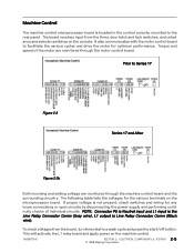
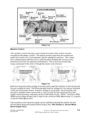
... performing continuity checks of the motor are monitored through the motor control board. ELECTRICAL COMPONENTS & TESTING 2 - 5 © 1998 Maytag Corporation The following table lists the voltages for...motor control board to the rear panel. If proper voltage is Line Relay Connector Comm (Black wire). Torque and speed of individual circuits. Machine Control The machine control microprocessor board is located in the control console, mounted to facilitate the various cycles and drive the motor for optimum performance. The board receives input from the board, turn timer dial to Series...
... performing continuity checks of the motor are monitored through the motor control board. ELECTRICAL COMPONENTS & TESTING 2 - 5 © 1998 Maytag Corporation The following table lists the voltages for...motor control board to the rear panel. If proper voltage is Line Relay Connector Comm (Black wire). Torque and speed of individual circuits. Machine Control The machine control microprocessor board is located in the control console, mounted to facilitate the various cycles and drive the motor for optimum performance. The board receives input from the board, turn timer dial to Series...
Service Manual
Page 27
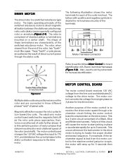
... are pulled as the rotor pole piece approaches; ELECTRICAL COMPONENTS & TESTING 2 - 7 © 1998 Maytag Corporation The shape of the rotor (and shaft). The motor control board receives 120 VAC voltage from the end of the switched reluctance motor. DRIVE MOTOR The drive motor is this circuit will ramp up for up to 5 seconds. The rotor is lost...
... are pulled as the rotor pole piece approaches; ELECTRICAL COMPONENTS & TESTING 2 - 7 © 1998 Maytag Corporation The shape of the rotor (and shaft). The motor control board receives 120 VAC voltage from the end of the switched reluctance motor. DRIVE MOTOR The drive motor is this circuit will ramp up for up to 5 seconds. The rotor is lost...
Service Manual
Page 28
... the washer power cord and replace motor control board connector JP4 when finished. Remove JP4 Interface connector wire harness on the heat sink for damage (See Drive Motor). If fuse and semiconductors show no . 13) on the control board, either visually or with a large load (See Section 3: Troubleshooting). 16008373-01 SECTION 2. ELECTRICAL COMPONENTS & TESTING 2 - 8 © 1998 Maytag Corporation Replace motor...
... the washer power cord and replace motor control board connector JP4 when finished. Remove JP4 Interface connector wire harness on the heat sink for damage (See Drive Motor). If fuse and semiconductors show no . 13) on the control board, either visually or with a large load (See Section 3: Troubleshooting). 16008373-01 SECTION 2. ELECTRICAL COMPONENTS & TESTING 2 - 8 © 1998 Maytag Corporation Replace motor...
Service Manual
Page 29
... to the washer prior to the wire harness. 16008373-01 SECTION 2. Reconnect the ground wire, line 1 and neutral wires. If the motor operates with phase A disconnected. Carefully lift the front end of the motor control board. ELECTRICAL COMPONENTS & TESTING © 1998 Maytag Corporation 2-9 Reassemble the drip shield cover onto the motor control. 8. Perform the motor 5. Reposition the motor control into the motor. 4. Check...
... to the washer prior to the wire harness. 16008373-01 SECTION 2. Reconnect the ground wire, line 1 and neutral wires. If the motor operates with phase A disconnected. Carefully lift the front end of the motor control board. ELECTRICAL COMPONENTS & TESTING © 1998 Maytag Corporation 2-9 Reassemble the drip shield cover onto the motor control. 8. Perform the motor 5. Reposition the motor control into the motor. 4. Check...
Service Manual
Page 30
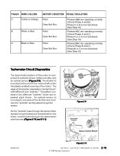
...harness (Figure 2-10 and 2-11). The edge of the motor. Figure 2-9 16008373-01 Figure 2-10 SECTION 2. ELECTRICAL COMPONENTS & TESTING 2-10 © 1998 Maytag Corporation An optical sensor is mounted to the motor control board through the sensor. PHASE WIRE COLORS C Yellow or Orange ...B White or Red A Black or Blue MOTOR CONDITION RESULT/SOLUTION Runs Does Not Run Runs Does ...
...harness (Figure 2-10 and 2-11). The edge of the motor. Figure 2-9 16008373-01 Figure 2-10 SECTION 2. ELECTRICAL COMPONENTS & TESTING 2-10 © 1998 Maytag Corporation An optical sensor is mounted to the motor control board through the sensor. PHASE WIRE COLORS C Yellow or Orange ...B White or Red A Black or Blue MOTOR CONDITION RESULT/SOLUTION Runs Does Not Run Runs Does ...
Service Manual
Page 31
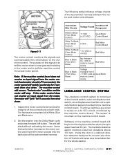
...motor and motor control board. If the motor control does not receive an input signal from the motor control/tachometer circuit (JP4 connector), the motor speed will "jerk" for 5 seconds then shut down . 1. Tachometer Wire Checks Voltage Found Condition Of Component White to the machine control. Set the washer... into the back side of a White, Blue and Black wire. 2. Note: If the machine control board does not receive an input signal from the motor, the motor will rapidly accelerate for 5 seconds then...
...motor and motor control board. If the motor control does not receive an input signal from the motor control/tachometer circuit (JP4 connector), the motor speed will "jerk" for 5 seconds then shut down . 1. Tachometer Wire Checks Voltage Found Condition Of Component White to the machine control. Set the washer... into the back side of a White, Blue and Black wire. 2. Note: If the machine control board does not receive an input signal from the motor, the motor will rapidly accelerate for 5 seconds then...
Service Manual
Page 35
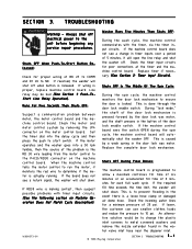
...). Runs For Five Seconds Then Shuts OFF: Suspect a communication problem between motor, the motor control board and the machine control board. If the motor operates and the washer goes into the delay cycle and then press the push to COMM Washer Runs Five Minutes Then Shuts OFF: During the wash cycle, the machine... button of 20 psi. Shuts OFF During Final Rinses: The machine control board is released. During "lock mode," the shaft of BK 27 to start switch. If lower, the customer can use smaller clothes loads and reduce the pressure to the unit before beginning any service repair ...
...). Runs For Five Seconds Then Shuts OFF: Suspect a communication problem between motor, the motor control board and the machine control board. If the motor operates and the washer goes into the delay cycle and then press the push to COMM Washer Runs Five Minutes Then Shuts OFF: During the wash cycle, the machine... button of 20 psi. Shuts OFF During Final Rinses: The machine control board is released. During "lock mode," the shaft of BK 27 to start switch. If lower, the customer can use smaller clothes loads and reduce the pressure to the unit before beginning any service repair ...
Service Manual
Page 78
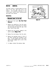
The assembly comprises of the cabinet. MOTOR DRIVE SYSTEM © 1998 Maytag Corporation 8-3 To replace, reverse the previous steps. REMOVAL 1 . Remove the wire harness from the motor control board by depressing the locking tab found along the lower left side of the motor securing the assembly to the base. Remove two mounting screws in the base frame...
The assembly comprises of the cabinet. MOTOR DRIVE SYSTEM © 1998 Maytag Corporation 8-3 To replace, reverse the previous steps. REMOVAL 1 . Remove the wire harness from the motor control board by depressing the locking tab found along the lower left side of the motor securing the assembly to the base. Remove two mounting screws in the base frame...
Service Manual
Page 89
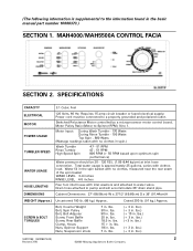
...Motor controlled by a microprocessor motor control board...Belt Adjuster Screw, Front Baffle Screw, ...washers and attached to the information found in . lbs. 90 in . lbs. 18 in . lbs.) (+ 10 in . MAH4000/MAH5500A CONTROL FACIA SECTION 2. lbs.) (+ 3 in . lbs. 18.5 in . lbs.) 16010199 (16008373-03) 2 Revised 7/00 ©2000 Maytag...27" (68.58cm) W x 271/2" (69.85cm) D x 36" (91.44cm)H WEIGHT (Approx.) SCREW & BOLT TORQUES Uncartoned 190 lb. (86 kg.) Approx. lbs.) (+ 3 in . lbs. 30 in . (The following information is approximately 25 gallons, varies with clothes load...
...Motor controlled by a microprocessor motor control board...Belt Adjuster Screw, Front Baffle Screw, ...washers and attached to the information found in . lbs. 90 in . lbs. 18 in . lbs.) (+ 10 in . MAH4000/MAH5500A CONTROL FACIA SECTION 2. lbs.) (+ 3 in . lbs. 18.5 in . lbs.) 16010199 (16008373-03) 2 Revised 7/00 ©2000 Maytag...27" (68.58cm) W x 271/2" (69.85cm) D x 36" (91.44cm)H WEIGHT (Approx.) SCREW & BOLT TORQUES Uncartoned 190 lb. (86 kg.) Approx. lbs.) (+ 3 in . lbs. 30 in . (The following information is approximately 25 gallons, varies with clothes load...
Service Manual
Page 109
Switched Reluctance Motor controlled by a microprocessor motor control board. LCD Washer (MAH7500A) Water pressure should be connected to 1 (MAH7500A) Motor Input: During Wash Tumble - 170 Watts During Wash Tumble w/heater - 1300Watts During Rinse Tumble - 195 Watts Top Spin ... with clothes load. lbs. lbs.) (+ 3 in . lbs.) (+ 3 ft. lbs. 18.5 in . lbs. 18 ft. lbs.) (+3 in . lbs.) 16010486 (16008373-05) Revised 02/01 Section 1. Total water usage is approximately 25 gallons, varies with no clothes in . Drain hose attached to water valve. Cabinet Dimensions: 27" (68....
Switched Reluctance Motor controlled by a microprocessor motor control board. LCD Washer (MAH7500A) Water pressure should be connected to 1 (MAH7500A) Motor Input: During Wash Tumble - 170 Watts During Wash Tumble w/heater - 1300Watts During Rinse Tumble - 195 Watts Top Spin ... with clothes load. lbs. lbs.) (+ 3 in . lbs.) (+ 3 ft. lbs. 18.5 in . lbs. 18 ft. lbs.) (+3 in . lbs.) 16010486 (16008373-05) Revised 02/01 Section 1. Total water usage is approximately 25 gallons, varies with no clothes in . Drain hose attached to water valve. Cabinet Dimensions: 27" (68....
Service Manual
Page 110
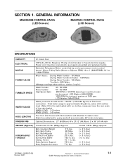
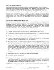
...motor control board. Heater with thermistor was relocated from the clothes. 16010486 (16008373-05) Revised 02/01 Section 1. The number of the pump, thus eliminating the airdome hose. During the final rinse the machine will perform a tumble flush to clean the machine. 10) A final drain and high speed spin will be dispensed. 8) The washer... and some warmer rinses. A Wash Tumble Flush will have a 7/3 tumble pattern. General Information ©2001 Maytag Appliances Sales Company 1-2 The temperature of the detergent and the wash water. Note: No permanent locking, tumbling,...
...motor control board. Heater with thermistor was relocated from the clothes. 16010486 (16008373-05) Revised 02/01 Section 1. The number of the pump, thus eliminating the airdome hose. During the final rinse the machine will perform a tumble flush to clean the machine. 10) A final drain and high speed spin will be dispensed. 8) The washer... and some warmer rinses. A Wash Tumble Flush will have a 7/3 tumble pattern. General Information ©2001 Maytag Appliances Sales Company 1-2 The temperature of the detergent and the wash water. Note: No permanent locking, tumbling,...
Service Manual
Page 132
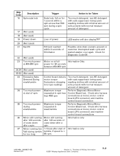
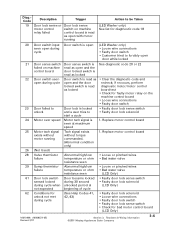
... 23 Too much power Motor on for 1 second within 2 seconds of fill initation Possible slow drain scenario present or customer interrupted wash cycle and started washer over again. Teardown & Wiring Information ©2001 Maytag Appliances Sales Company 3-2...Motor/Motor at start of spin requested in spin less Control Board test. Check wire harness connections at motor, motor control board (JP4 connector) and machine control board connections 36 Motor still running Motor still running too 1 minute after 120 seconds of of coast down coast down Loss of power LED washer...
... 23 Too much power Motor on for 1 second within 2 seconds of fill initation Possible slow drain scenario present or customer interrupted wash cycle and started washer over again. Teardown & Wiring Information ©2001 Maytag Appliances Sales Company 3-2...Motor/Motor at start of spin requested in spin less Control Board test. Check wire harness connections at motor, motor control board (JP4 connector) and machine control board connections 36 Motor still running Motor still running too 1 minute after 120 seconds of of coast down coast down Loss of power LED washer...
Service Manual
Page 133
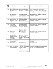
...verify tack signal during unlock request No tach signal observed when motor control is not locked Control Board test. Refer to Diagnostic powered during because motor code 62 (LCD Only) unlock control not powered during unlock request 43 Tach signal unexpectedly present ...Maytag Appliances Sales Company 3-3 Refer to be Taken 40 Motor running and Motor running and Perform Diagnostic Motor/Motor the Door is not the door is powered at the end of the failed fast powerup and unlocks retries Informative only; Check wire harness locked connections at motor, motor control board...
...verify tack signal during unlock request No tach signal observed when motor control is not locked Control Board test. Refer to Diagnostic powered during because motor code 62 (LCD Only) unlock control not powered during unlock request 43 Tach signal unexpectedly present ...Maytag Appliances Sales Company 3-3 Refer to be Taken 40 Motor running and Motor running and Perform Diagnostic Motor/Motor the Door is not the door is powered at the end of the failed fast powerup and unlocks retries Informative only; Check wire harness locked connections at motor, motor control board...
Service Manual
Page 135
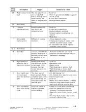
... ©2001 Maytag Appliances Sales Company 3-5 Perform membrane pad check pressed more than 75 2. if re-occures, perform diagnostic motor/motor control board test •Check for : •Loose wire connections •Faulty unbalance switches •Unlevel washer; Clear diagnostic codes 2. Diag. Unplug and replug in the pressure switch Action to an unbalanced load Difficulty in reading...
... ©2001 Maytag Appliances Sales Company 3-5 Perform membrane pad check pressed more than 75 2. if re-occures, perform diagnostic motor/motor control board test •Check for : •Loose wire connections •Faulty unbalance switches •Unlevel washer; Clear diagnostic codes 2. Diag. Unplug and replug in the pressure switch Action to an unbalanced load Difficulty in reading...
Service Manual
Page 136
... door switch • Customer tried to be Taken (LED Washer only) See list for bad motor control board (LCD Only) 16010486 (16008373-05) Revised 2/01 Section 3. Replace motor control board exists without without torque motor running Action to forcibly open door while locked 21 Door sense...code 20 or 22 failed on machine relay failed control board is read as open and the door recheck; Replace motor control board 25 Motor tach signal Tach signal exists 1. Teardown & Wiring Information ©2001 Maytag Appliances Sales Company 3-6 Diag.Code Description Trigger ...
... door switch • Customer tried to be Taken (LED Washer only) See list for bad motor control board (LCD Only) 16010486 (16008373-05) Revised 2/01 Section 3. Replace motor control board exists without without torque motor running Action to forcibly open door while locked 21 Door sense...code 20 or 22 failed on machine relay failed control board is read as open and the door recheck; Replace motor control board 25 Motor tach signal Tach signal exists 1. Teardown & Wiring Information ©2001 Maytag Appliances Sales Company 3-6 Diag.Code Description Trigger ...
Service Manual
Page 141
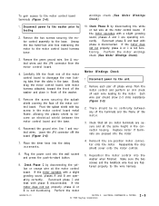
...169;2001 Maytag Appliances Sales Company 4-1 Always shut off the machine control and locate the P3(6) and P3(7) leads in the connector on the control board for the door lock mechanism is disabled if the motor control board indicates the spinner speed is similar to the washer before beginning ...any service repair procedures. Place the washer into Service Mode. (See Section 2; Accessing Service...
...169;2001 Maytag Appliances Sales Company 4-1 Always shut off the machine control and locate the P3(6) and P3(7) leads in the connector on the control board for the door lock mechanism is disabled if the motor control board indicates the spinner speed is similar to the washer before beginning ...any service repair procedures. Place the washer into Service Mode. (See Section 2; Accessing Service...
Service Manual
Page 142
... the motor control board to the plastic console. If proper voltage is done by monitoring torque and speed of individual circuits. The following table lists the voltages for possible loose connections or open circuits by placing the washer into the Service Mode and performing a Board Output Test. (See Section 2; Electrical Components & Testing ©2001 Maytag Appliances...
... the motor control board to the plastic console. If proper voltage is done by monitoring torque and speed of individual circuits. The following table lists the voltages for possible loose connections or open circuits by placing the washer into the Service Mode and performing a Board Output Test. (See Section 2; Electrical Components & Testing ©2001 Maytag Appliances...
Service Manual
Page 145
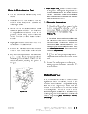
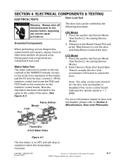
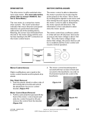
.... Drip Shield Removal 1. MOTOR CONTROL BOARD The motor control is a sensorless motor drive system. Meaning, the sensor was eliminated from the end of the locking tab to the RPT connection on the motor control board. Figure 4-4 Figure 4-5 16010486 (16008373-05) Revised 02/01 Section 4. Electrical Components & Testing ©2001 Maytag Appliances Sales Company 4-5 Drive Motor.) The new motor is able to determine...
.... Drip Shield Removal 1. MOTOR CONTROL BOARD The motor control is a sensorless motor drive system. Meaning, the sensor was eliminated from the end of the locking tab to the RPT connection on the motor control board. Figure 4-4 Figure 4-5 16010486 (16008373-05) Revised 02/01 Section 4. Electrical Components & Testing ©2001 Maytag Appliances Sales Company 4-5 Drive Motor.) The new motor is able to determine...


