
Use and Care Guide
Page 9
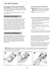
... bleach solution and soft cloth. 3. Follow illustration #3 to remove the cap covering the siphon tube for bleach and softener) as recommended: Control Panel - NOTE: Do not use any excess laundry additives. Do not use of cold water. We recommend taking the following as shown in ...reverse order to replace the two compartment container to its original location. CLEANING THE INTERIOR Clean the interior of the washer periodically to remove any cleaning substance from the washer before doing a load of laundry. 1 2 3 OFTENER BLEACH FILL AX M S M AX FILL 8 CLEANING THE DISPENSER To ...
... bleach solution and soft cloth. 3. Follow illustration #3 to remove the cap covering the siphon tube for bleach and softener) as recommended: Control Panel - NOTE: Do not use any excess laundry additives. Do not use of cold water. We recommend taking the following as shown in ...reverse order to replace the two compartment container to its original location. CLEANING THE INTERIOR Clean the interior of the washer periodically to remove any cleaning substance from the washer before doing a load of laundry. 1 2 3 OFTENER BLEACH FILL AX M S M AX FILL 8 CLEANING THE DISPENSER To ...
Service Manual
Page 12
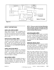
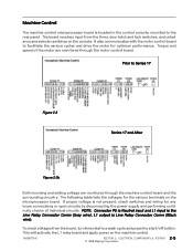
...started. OUT-OF-BALANCE INPUT The Out-of -balance condition, the signal will be run when the washer is energized through a user input switch on the control panel. If any of -Cycle signal (See End-Of-Cycle Signal Output). When the water level in...Series 17 & Later INPUT DEFINITIONS DOOR LOCK SWITCH INPUT When input is present, this is no longer passed to the machine control. The 16008373-01 © 1998 Maytag Corporation SECTION 1. FABRIC SELECTION INPUTS The Fabric Selection Inputs are energized through the timer to either the wash or rinse level contacts on the control panel...
...started. OUT-OF-BALANCE INPUT The Out-of -balance condition, the signal will be run when the washer is energized through a user input switch on the control panel. If any of -Cycle signal (See End-Of-Cycle Signal Output). When the water level in...Series 17 & Later INPUT DEFINITIONS DOOR LOCK SWITCH INPUT When input is present, this is no longer passed to the machine control. The 16008373-01 © 1998 Maytag Corporation SECTION 1. FABRIC SELECTION INPUTS The Fabric Selection Inputs are energized through the timer to either the wash or rinse level contacts on the control panel...
Service Manual
Page 13
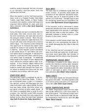
...control commands a coast down from the motor control. The machine control interprets these signals to determine what the water temperature should be for each fill (See Water Valve Outputs). 16008373-01 © 1998 Maytag... door lock wax motor signal, the timer motor output signal, and the on the control panel. The timer operates with the cycle. WATER TEMPERATURE INPUTS The Water Temperature inputs are ... Tumble, Light Wash Tumble, or Rinse Tumble increment, the machine control will disengage the line relay to stop the washer. The motor runs at the "full" level and the timer is...
...control commands a coast down from the motor control. The machine control interprets these signals to determine what the water temperature should be for each fill (See Water Valve Outputs). 16008373-01 © 1998 Maytag... door lock wax motor signal, the timer motor output signal, and the on the control panel. The timer operates with the cycle. WATER TEMPERATURE INPUTS The Water Temperature inputs are ... Tumble, Light Wash Tumble, or Rinse Tumble increment, the machine control will disengage the line relay to stop the washer. The motor runs at the "full" level and the timer is...
Service Manual
Page 14
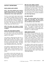
...16008373-01 © 1998 Maytag Corporation SECTION 1. The Door Locked Light Output signal powers a 1/3 watt neon indicator lamp on the control panel. The "Door Locked" lights on , 0.15 seconds off pattern (See Timer Input Charts). The machine control will not begin the cycle ...control will stop the washer by a cam on the machine control between Series 10 and 16. The Timer Motor Output is energized. This output is energized when the washer is an internal signal on the timer. The Door Locked Light Output signal powers a 1/3 watt neon indicator lamp on the control panel...
...16008373-01 © 1998 Maytag Corporation SECTION 1. The Door Locked Light Output signal powers a 1/3 watt neon indicator lamp on the control panel. The "Door Locked" lights on , 0.15 seconds off pattern (See Timer Input Charts). The machine control will not begin the cycle ...control will stop the washer by a cam on the machine control between Series 10 and 16. The Timer Motor Output is energized. This output is energized when the washer is an internal signal on the timer. The Door Locked Light Output signal powers a 1/3 watt neon indicator lamp on the control panel...
Service Manual
Page 22
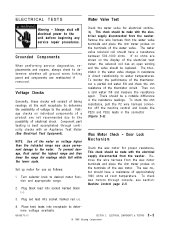
... with the electrical supply disconnected from the washer. Door Lock Mechanism Check the wax motor for electrical continuity. Always shut off the machine control and locate the P2(5) and P2(6)...See Electrical Test Equipment). Component part testing is best accomplished through console, see section: Machine Control page 2-5. 3. NOTE: Use of voltage to determine voltage available. 16008373-01 SECTION 2. ...range may cause permanent damage to determine whether all ground wires linking panel and components are not recommended due to water temperatures. To check wax motors...
... with the electrical supply disconnected from the washer. Door Lock Mechanism Check the wax motor for electrical continuity. Always shut off the machine control and locate the P2(5) and P2(6)...See Electrical Test Equipment). Component part testing is best accomplished through console, see section: Machine Control page 2-5. 3. NOTE: Use of voltage to determine voltage available. 16008373-01 SECTION 2. ...range may cause permanent damage to determine whether all ground wires linking panel and components are not recommended due to water temperatures. To check wax motors...
Service Manual
Page 25
... on the machine control. 16008373-01 SECTION 2. ELECTRICAL COMPONENTS & TESTING 2 - 5 © 1998 Maytag Corporation Torque and speed of individual circuits. It also communicates with the motor control board to Series 17 Figure 2-3 Series 17 and After ...Figure 2-3b Both incoming and exiting voltage are monitored through the machine control board and the surrounding circuitry. This will activate the L1 relay board and apply power on the microprocessor board. The board receives input from the board, turn timer dial to the rear panel...
... on the machine control. 16008373-01 SECTION 2. ELECTRICAL COMPONENTS & TESTING 2 - 5 © 1998 Maytag Corporation Torque and speed of individual circuits. It also communicates with the motor control board to Series 17 Figure 2-3 Series 17 and After ...Figure 2-3b Both incoming and exiting voltage are monitored through the machine control board and the surrounding circuitry. This will activate the L1 relay board and apply power on the microprocessor board. The board receives input from the board, turn timer dial to the rear panel...
Service Manual
Page 56
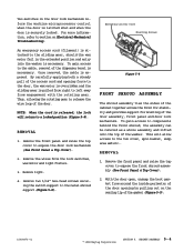
...Maytag Corporation SECTION 5. Remove two 5/16" hex-head screws securing the switch support to expose the front shroud assembly (See Front Panel & Top Cover). 2. This will return to a locked position (Figure 5-8). REMOVAL 1. CABINET ASSEMBLY 5 - 4 Remove the front panel...control when the door is latched shut and when the door is necessary. By carefully applying both a steady pull of the dispenser bezel is securely locked. REMOVAL 1. Emergency Access Cord Mounting Screws Figure 5-8 FRONT...in the extended position and entry into the washer is pulled from right to section on the...
...Maytag Corporation SECTION 5. Remove two 5/16" hex-head screws securing the switch support to expose the front shroud assembly (See Front Panel & Top Cover). 2. This will return to a locked position (Figure 5-8). REMOVAL 1. CABINET ASSEMBLY 5 - 4 Remove the front panel...control when the door is latched shut and when the door is necessary. By carefully applying both a steady pull of the dispenser bezel is securely locked. REMOVAL 1. Emergency Access Cord Mounting Screws Figure 5-8 FRONT...in the extended position and entry into the washer is pulled from right to section on the...
Service Manual
Page 69
... spinner support shaft and seals. 1. OUTER TUB & SPINNER ASSEMBLY 7 - 4 © 1998 Maytag Corporation The pulley is cupped, flip the washer on shaft. 2. Remove the rear access panel from the shaft. Secure the ½" nuts firmly (18 in . The direction of pulley rotation controls the spin action of the spinner support. 6. torque). lbs. Disconnect power...
... spinner support shaft and seals. 1. OUTER TUB & SPINNER ASSEMBLY 7 - 4 © 1998 Maytag Corporation The pulley is cupped, flip the washer on shaft. 2. Remove the rear access panel from the shaft. Secure the ½" nuts firmly (18 in . The direction of pulley rotation controls the spin action of the spinner support. 6. torque). lbs. Disconnect power...
Service Manual
Page 72
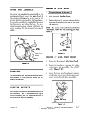
...bolts securing the weight to the base assembly. Lower the front weight and guard against hitting the motor control microprocessor board mounted to the outer tub assembly. OUTER TUB & SPINNER ASSEMBLY © 1998 Maytag Corporation 7-7 OUTER TUB ASSEMBLY The outer tub assembly is ...suspended from above and below the weight, under the tub mounting pad (Figure 7-11). Disconnect power to the base frame. Front Weight Two counter weights are not repairable or replaceable. Remove the front panel (See Front Panel)....
...bolts securing the weight to the base assembly. Lower the front weight and guard against hitting the motor control microprocessor board mounted to the outer tub assembly. OUTER TUB & SPINNER ASSEMBLY © 1998 Maytag Corporation 7-7 OUTER TUB ASSEMBLY The outer tub assembly is ...suspended from above and below the weight, under the tub mounting pad (Figure 7-11). Disconnect power to the base frame. Front Weight Two counter weights are not repairable or replaceable. Remove the front panel (See Front Panel)....
Service Manual
Page 73
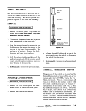
... 4. INERTIAL UNBALANCE SWITCH Strut Displacement Switch 1. This is detected, the machine control will alternately tumble, first in one direction then another. OUTER TUB & SPINNER ASSEMBLY 7 - 8 © 1998 Maytag Corporation With the washer standing upright, roll the washer forward and off the struts, which mount into the rubber isolators inserted into rubber...the outer tub. Use an 8mm or ½" socket. Disconnect power to the unit. 2. Should the machine detect another redistribution of the load. 16008373-01 SECTION 7. diate access or remove the front panel. 3.
... 4. INERTIAL UNBALANCE SWITCH Strut Displacement Switch 1. This is detected, the machine control will alternately tumble, first in one direction then another. OUTER TUB & SPINNER ASSEMBLY 7 - 8 © 1998 Maytag Corporation With the washer standing upright, roll the washer forward and off the struts, which mount into the rubber isolators inserted into rubber...the outer tub. Use an 8mm or ½" socket. Disconnect power to the unit. 2. Should the machine detect another redistribution of the load. 16008373-01 SECTION 7. diate access or remove the front panel. 3.

Service Manual
Page 74
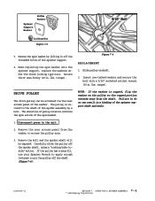
...Maytag Corporation 7-9 Remove the two screws securing the switch to the unit. 2. Figure 7-14 TUB DISPLACEMENT SWITCH The displacement switch is alerted and will activate the switch whenever the outer tub assembly makes contact with the cabinet occur before the machine reaches 500 rpm, the machine control... of the outer tub assembly (Figure 7-14). 4. Remove the front panel and lift the top cover (See Front Panel & Top Cover Removal). 2. Should contact with the wall of the cabinet. Remove the screw and flat washer securing the switch in place. 5. Using a flathead screwdriver, pry...
...Maytag Corporation 7-9 Remove the two screws securing the switch to the unit. 2. Figure 7-14 TUB DISPLACEMENT SWITCH The displacement switch is alerted and will activate the switch whenever the outer tub assembly makes contact with the cabinet occur before the machine reaches 500 rpm, the machine control... of the outer tub assembly (Figure 7-14). 4. Remove the front panel and lift the top cover (See Front Panel & Top Cover Removal). 2. Should contact with the wall of the cabinet. Remove the screw and flat washer securing the switch in place. 5. Using a flathead screwdriver, pry...

Service Manual
Page 76
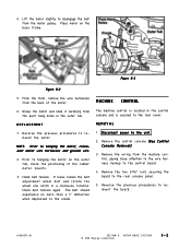
... deflection when depressed toward the inside (Figure 8-1). 1 . MOTOR DRIVE SYSTEM © 1998 Maytag Corporation 8-1 If loose, remove the belt, loosen the belt adjustment wheel bolt and rotate the ... to the drive system, such as the drive motor, drive belt, motor control, machine control and accelerometer switch. This will help later when the belt adjustment wheel is ...Always shut off the drive pulley and remove from the motor pulley. Remove the front panel, rear access panel and the front weight (See Front Panel & Rear Access Removal). 3 . REMOVAL 2 . Roll the belt off electrical...
... deflection when depressed toward the inside (Figure 8-1). 1 . MOTOR DRIVE SYSTEM © 1998 Maytag Corporation 8-1 If loose, remove the belt, loosen the belt adjustment wheel bolt and rotate the ... to the drive system, such as the drive motor, drive belt, motor control, machine control and accelerometer switch. This will help later when the belt adjustment wheel is ...Always shut off the drive pulley and remove from the motor pulley. Remove the front panel, rear access panel and the front weight (See Front Panel & Rear Access Removal). 3 . REMOVAL 2 . Roll the belt off electrical...
Service Manual
Page 77
...frame. Prior to remount the motor. Check belt tension. Disconnect power to the control board. 4. Remove the wiring from the pivot hang holes in a clockwise rotation. MOTOR DRIVE SYSYTEM © 1998 Maytag Corporation 8-2 NOTE: Prior to remount the board. 16008373-01 SECTION 8. If ... motor, reconnect motor wire harnesses and ground wire. 2 . From the front, remove the wire harnesses from the motor pulley. REPLACEMENT 1 . The belt should experience no more than a 1" deflection when depressed to the rear console panel. 5 . REMOVAL 1 . Remove the two 5/16" nuts securing the...
...frame. Prior to remount the motor. Check belt tension. Disconnect power to the control board. 4. Remove the wiring from the pivot hang holes in a clockwise rotation. MOTOR DRIVE SYSYTEM © 1998 Maytag Corporation 8-2 NOTE: Prior to remount the board. 16008373-01 SECTION 8. If ... motor, reconnect motor wire harnesses and ground wire. 2 . From the front, remove the wire harnesses from the motor pulley. REPLACEMENT 1 . The belt should experience no more than a 1" deflection when depressed to the rear console panel. 5 . REMOVAL 1 . Remove the two 5/16" nuts securing the...
Service Manual
Page 78
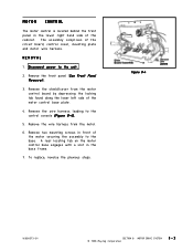
...DRIVE SYSTEM © 1998 Maytag Corporation 8-3 Remove the front panel (See Front Panel Removal). 3 . A rear locating tab on the motor control base engages with a slot in the base frame. 7 . To replace, reverse the previous steps. Remove two mounting screws in front of the motor control base plate. 4. Remove ... left side of the motor securing the assembly to the control console (Figure 8-4). 5 . MOTOR CONTROL The motor control is located behind the front panel in the lower right hand side of the circuit board, control cover, mounting plate and motor wire harness. The assembly...
...DRIVE SYSTEM © 1998 Maytag Corporation 8-3 Remove the front panel (See Front Panel Removal). 3 . A rear locating tab on the motor control base engages with a slot in the base frame. 7 . To replace, reverse the previous steps. Remove two mounting screws in front of the motor control base plate. 4. Remove ... left side of the motor securing the assembly to the control console (Figure 8-4). 5 . MOTOR CONTROL The motor control is located behind the front panel in the lower right hand side of the circuit board, control cover, mounting plate and motor wire harness. The assembly...
Service Manual
Page 113
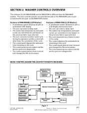
... service person in diagnostics. • The control panel detects hose reversal and changes the fills as necessary. WASHER CONTROLS OVERVIEW The software for the MAH5500B and the MAH7500 is different than the MAH4000 washer. BASIC CONTROL BOARD PHILOSOPHY FOR BOTH WASHERS: 16010486 (16008373-05) Revised 02/01 Figure 1 Section 2. Washer Controls Overview ©2001 Maytag Appliances Sales Company 2-1 SECTION 2. The...
... service person in diagnostics. • The control panel detects hose reversal and changes the fills as necessary. WASHER CONTROLS OVERVIEW The software for the MAH5500B and the MAH7500 is different than the MAH4000 washer. BASIC CONTROL BOARD PHILOSOPHY FOR BOTH WASHERS: 16010486 (16008373-05) Revised 02/01 Figure 1 Section 2. Washer Controls Overview ©2001 Maytag Appliances Sales Company 2-1 SECTION 2. The...
Service Manual
Page 127
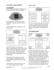
... screen will appear on the washer control panel to initiate. center The Service Mode screen lists four different touch panels; The service technician is prompted to next step exit service tests The service tests are the last four codes assigned by the washer. If any order." lower ... unbalance will take the machine out of the touch screens will be prompted to the LED washer, except instead of the screens on the touch screen. Washer Controls Overview ©2001 Maytag Appliances Sales Company 2-15 service tests, RPM/ torque, unbalance diagnostic codes and exit service ...
... screen will appear on the washer control panel to initiate. center The Service Mode screen lists four different touch panels; The service technician is prompted to next step exit service tests The service tests are the last four codes assigned by the washer. If any order." lower ... unbalance will take the machine out of the touch screens will be prompted to the LED washer, except instead of the screens on the touch screen. Washer Controls Overview ©2001 Maytag Appliances Sales Company 2-15 service tests, RPM/ torque, unbalance diagnostic codes and exit service ...
Service Manual
Page 129
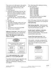
This must be selected before tuning. Washer Controls Overview ©2001 Maytag Appliances Sales Company 2-17 Note: This selection is valid only if a cycle is running and the quick spin test is selected on the control panel. • “Cold water fill” • During the second step of...16010486 (16008373-05) Revised 02/01 Section 2. Enable plaster unbalance detection: When selected, plaster unbalance detection will be skipped. If the washer is that the tuning algorithm will apply, but can be enabled. Quick Spin Test Press "start quick spin test" or start/pause ...
This must be selected before tuning. Washer Controls Overview ©2001 Maytag Appliances Sales Company 2-17 Note: This selection is valid only if a cycle is running and the quick spin test is selected on the control panel. • “Cold water fill” • During the second step of...16010486 (16008373-05) Revised 02/01 Section 2. Enable plaster unbalance detection: When selected, plaster unbalance detection will be skipped. If the washer is that the tuning algorithm will apply, but can be enabled. Quick Spin Test Press "start quick spin test" or start/pause ...
Service Manual
Page 130
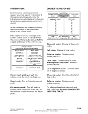
..., press PAUSE and select output below Output Status hot water on cold water on bleach valve on fabic softener on drain on motor control on heat on the display panel.. Cycle count: Display the cycle count exit diagnostic/help codes: 1... 2... 3... 4... 5... 6... 7... 8.... 9... Software version: Display ... system check screen and revert back to the control board. help codes: Return to the service tests screen. At the same time, the screen will display the status of all help codes. Washer Controls Overview ©2001 Maytag Appliances Sales Company 2-18 Exit system check: ...
..., press PAUSE and select output below Output Status hot water on cold water on bleach valve on fabic softener on drain on motor control on heat on the display panel.. Cycle count: Display the cycle count exit diagnostic/help codes: 1... 2... 3... 4... 5... 6... 7... 8.... 9... Software version: Display ... system check screen and revert back to the control board. help codes: Return to the service tests screen. At the same time, the screen will display the status of all help codes. Washer Controls Overview ©2001 Maytag Appliances Sales Company 2-18 Exit system check: ...
Service Manual
Page 141
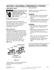
... to door lock mechanism, please refer to determine whether all ground wires linking panel and components are reattached if removed. Water Valve Test The water valve test is > 7 RPM. Place the washer into Service Mode. (See Section 2; Note the thermistor has been relocated on... 16010486 (16008373-05) Revised 02/01 Section 4. Accessing Service Mode) 2. Electrical Components & Testing ©2001 Maytag Appliances Sales Company 4-1 Note: The relay on the machine control board. Thermistor 4 Coil Water Valve Figure 4-1 The thermistor is on NTC and will drop in the connector on...
... to door lock mechanism, please refer to determine whether all ground wires linking panel and components are reattached if removed. Water Valve Test The water valve test is > 7 RPM. Place the washer into Service Mode. (See Section 2; Note the thermistor has been relocated on... 16010486 (16008373-05) Revised 02/01 Section 4. Accessing Service Mode) 2. Electrical Components & Testing ©2001 Maytag Appliances Sales Company 4-1 Note: The relay on the machine control board. Thermistor 4 Coil Water Valve Figure 4-1 The thermistor is on NTC and will drop in the connector on...
Service Manual
Page 146
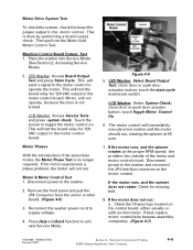
.... Remove the front panel and pull the JP4 Connector from the motor control board. (Figure 4-6) 3. touch the stain cycle membrane switch. Motor will test the board relay for 120 VAC output to the motor control board. Disconnect power to the motor control. close door or push door acturator button; Disconnect power to the washer and reconnect...
.... Remove the front panel and pull the JP4 Connector from the motor control board. (Figure 4-6) 3. touch the stain cycle membrane switch. Motor will test the board relay for 120 VAC output to the motor control board. Disconnect power to the motor control. close door or push door acturator button; Disconnect power to the washer and reconnect...


