
Use and Care Guide
Page 11
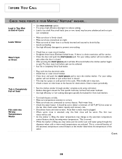
... cold. • As the washer is too small.Very small loads (one or two items) may change as the washer determines the temperature of Suds below. This is a drain restriction, call for front load washers. Won't Spin or Drain • Check fuse or reset circuit breaker. • Straighten drain hoses. BEFORE YOU CALL CHECK THESE POINTS IF YOUR MAYTAG® NEPTUNE® WASHER...
... cold. • As the washer is too small.Very small loads (one or two items) may change as the washer determines the temperature of Suds below. This is a drain restriction, call for front load washers. Won't Spin or Drain • Check fuse or reset circuit breaker. • Straighten drain hoses. BEFORE YOU CALL CHECK THESE POINTS IF YOUR MAYTAG® NEPTUNE® WASHER...
Use and Care Guide
Page 13
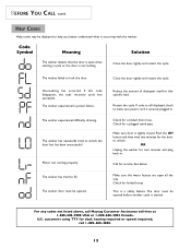
...drain hose. This is securely plugged in . customers using TTY for a plugged stand pipe. Close the door tightly and restart the cycle. Make sure door is occurring with the washer. See below. The washer experienced a power failure. The washer has tried to lock the door. Check for deaf, hearing impaired or speech impaired, call Maytag...kinked hoses. BEFORE YOU CALL CONT. HELP CODES Help codes may be opened before another cycle is not locking. U.S. Code Symbol Meaning Solution The washer detects that specific load. The washer experienced difficulty draining. The...
...drain hose. This is securely plugged in . customers using TTY for a plugged stand pipe. Close the door tightly and restart the cycle. Make sure door is occurring with the washer. See below. The washer experienced a power failure. The washer has tried to lock the door. Check for deaf, hearing impaired or speech impaired, call Maytag...kinked hoses. BEFORE YOU CALL CONT. HELP CODES Help codes may be opened before another cycle is not locking. U.S. Code Symbol Meaning Solution The washer detects that specific load. The washer experienced difficulty draining. The...
Service Manual
Page 5
... W/REAR ACCESS PANEL 5-5 SECTION 6. T R O U B L E S H O O T I O N 3 . WATER CARRYING COMPONENTS 6 - 1 WATER VALVE...6 - 1 WATER LEVEL PRESSURE SWITCH...6-2 AIR DOME HOSE ...6-2 DISPENSER ASSEMBLY ...6-3 FRONT WATER FLUME INJECTOR...6-4 PUMP ASSEMBLY ...6-4 Pump Accessory ...6-5 DRAIN HOSE ...6-6 SECTION 7. S E C T I N G ...3 - 1 DIAGNOSTIC FLOW CHARTS...3-4 Fills and Will Not Tumble ...3-4 Washer Overfills ...3-5 Washer Will Not Spin ...3-6 Machine Stalls During Spin ...3-8 Maximum Spin Speed Is Not Reached 3-9 Wash Cycle Takes...
... W/REAR ACCESS PANEL 5-5 SECTION 6. T R O U B L E S H O O T I O N 3 . WATER CARRYING COMPONENTS 6 - 1 WATER VALVE...6 - 1 WATER LEVEL PRESSURE SWITCH...6-2 AIR DOME HOSE ...6-2 DISPENSER ASSEMBLY ...6-3 FRONT WATER FLUME INJECTOR...6-4 PUMP ASSEMBLY ...6-4 Pump Accessory ...6-5 DRAIN HOSE ...6-6 SECTION 7. S E C T I N G ...3 - 1 DIAGNOSTIC FLOW CHARTS...3-4 Fills and Will Not Tumble ...3-4 Washer Overfills ...3-5 Washer Will Not Spin ...3-6 Machine Stalls During Spin ...3-8 Maximum Spin Speed Is Not Reached 3-9 Wash Cycle Takes...
Service Manual
Page 7
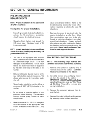
...16008373-01 © 1998 Maytag Corporation SECTION 1. Remove the carton by the drain hose strap on the back of the washer. • Hot and Cold water faucets must be removed later during the spin cycle. CAUTION: Hoses are also contributing factors to...washer installed on a platform or weak support structure. Refer to the troubleshooting section for more information regarding a solution for proper installation: • Properly grounded electrical outlet is recommended. Remove the crate bottom from unbalanced load situations. is obtained with a siphon break, and the drain hose...
...16008373-01 © 1998 Maytag Corporation SECTION 1. Remove the carton by the drain hose strap on the back of the washer. • Hot and Cold water faucets must be removed later during the spin cycle. CAUTION: Hoses are also contributing factors to...washer installed on a platform or weak support structure. Refer to the troubleshooting section for more information regarding a solution for proper installation: • Properly grounded electrical outlet is recommended. Remove the crate bottom from unbalanced load situations. is obtained with a siphon break, and the drain hose...
Service Manual
Page 9
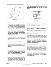
... a properly grounded and polarized three (3) prong receptacle (Figure 1-6). 16008373-01 © 1998 Maytag Corporation SECTION 1. Slide the washer into position to confirm levelness to the drain strap . Then route the drain hose through the drain hose strap on all four (4) legs (Figure 1-3). 6. When the washer is the personal responsibility of installation. Turn on the water valve bracket for...
... a properly grounded and polarized three (3) prong receptacle (Figure 1-6). 16008373-01 © 1998 Maytag Corporation SECTION 1. Slide the washer into position to confirm levelness to the drain strap . Then route the drain hose through the drain hose strap on all four (4) legs (Figure 1-3). 6. When the washer is the personal responsibility of installation. Turn on the water valve bracket for...
Service Manual
Page 61
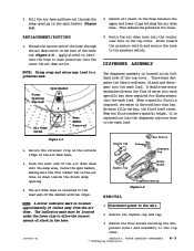
... air dome down inside the drain sump opening in the spin basket (Figure 6-3). 5. Remove the siphon cup and cap. 3. WATER CARRYING COMPONENTS © 1998 Maytag Corporation 6-3 Pull the air dome and hose out through the air dome outlet in the rear of the hose through the sump opening ....Linkage Wax Motors Dispenser Top 3. Disconnect power to the top cover. 16008373-01 SECTION 6. The dispenser assembly is retained to the wash load. As water fills the bay, the fluid level rises. Siphon Cup Rotary Nozzle REMOVAL Dispenser Bottom Figure 6-4 NOTE: A silver indicator ...
... air dome down inside the drain sump opening in the spin basket (Figure 6-3). 5. Remove the siphon cup and cap. 3. WATER CARRYING COMPONENTS © 1998 Maytag Corporation 6-3 Pull the air dome and hose out through the air dome outlet in the rear of the hose through the sump opening ....Linkage Wax Motors Dispenser Top 3. Disconnect power to the top cover. 16008373-01 SECTION 6. The dispenser assembly is retained to the wash load. As water fills the bay, the fluid level rises. Siphon Cup Rotary Nozzle REMOVAL Dispenser Bottom Figure 6-4 NOTE: A silver indicator ...
Service Manual
Page 62
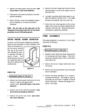
...; 1998 Maytag Corporation Remove the outer tub cover (See Outer Tub Cover Removal). 16008373-01 SECTION 6. While lifting, rotate the dispenser assembly 90 degrees in the base. Spread a towel below the drain hoses prior to... remove the injector, place a 5/8" - 3/4" wedge between the spinner and the outer tub. 7. Remove the hose clamps and hoses from the spout on the front upper area ... to the right rear area of the pump are slotted to saturate the clothes load. Figure 6-5 REMOVAL 1. Disconnect power to replace the injector. 4. Pinch the...
...; 1998 Maytag Corporation Remove the outer tub cover (See Outer Tub Cover Removal). 16008373-01 SECTION 6. While lifting, rotate the dispenser assembly 90 degrees in the base. Spread a towel below the drain hoses prior to... remove the injector, place a 5/8" - 3/4" wedge between the spinner and the outer tub. 7. Remove the hose clamps and hoses from the spout on the front upper area ... to the right rear area of the pump are slotted to saturate the clothes load. Figure 6-5 REMOVAL 1. Disconnect power to replace the injector. 4. Pinch the...
Service Manual
Page 63
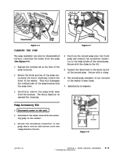
... on the face of the washer. This will disengage the locking tabs of the pump housing from the housing. Disconnect the drain hose from the pump (See Figure 6-6). 1. Figure 6-8 16008373-01 SECTION 6. Installation is exposed for cleaning. The drain impeller is complete. 3. WATER CARRYING COMPONENTS © 1998 Maytag Corporation 6-5 Connect the drain hose to the sump intake...
... on the face of the washer. This will disengage the locking tabs of the pump housing from the housing. Disconnect the drain hose from the pump (See Figure 6-6). 1. Figure 6-8 16008373-01 SECTION 6. Installation is exposed for cleaning. The drain impeller is complete. 3. WATER CARRYING COMPONENTS © 1998 Maytag Corporation 6-5 Connect the drain hose to the sump intake...

Service Manual
Page 64
... a shield. Reverse the previous steps for replacement. Loosen the clamp and remove the drain hose (Figure 6-10). 5. Remove the ¼" hex head screw securing the drain hose shield. Drain Hose Drain Hose Access Cover Figure 6-9 Clamp Figure 6-10 16008373-01 SECTION 6. WATER CARRYING COMPONENTS 6-6 © 1998 Maytag Corporation Disconnect power to the rear wall of the cabinet. 3. With access...
... a shield. Reverse the previous steps for replacement. Loosen the clamp and remove the drain hose (Figure 6-10). 5. Remove the ¼" hex head screw securing the drain hose shield. Drain Hose Drain Hose Access Cover Figure 6-9 Clamp Figure 6-10 16008373-01 SECTION 6. WATER CARRYING COMPONENTS 6-6 © 1998 Maytag Corporation Disconnect power to the rear wall of the cabinet. 3. With access...
Service Manual
Page 89
... 14 to pump and will accommodate 36" drain stand pipe. Drain hose attached to 1. lbs. 18.5 in .... Screw, Front Baffle Screw, Rear Baffle Clamp, Hoses Nuts, Spinner Support Nuts, Suspension struts 7 in . lbs.) (+ 3 in . Cabinet Dimensions: 27" (68...washers and attached to a properly grounded and polarized outlet. lbs. 90 in . lbs. 18 in . Requires 15 amp circuit breaker or fused electrical supply. Switched Reluctance Motor controlled by a microprocessor motor control board. Crated 200 lb. (91 kg.) Approx. (+ 3 in . lbs.) 16010199 (16008373-03) 2 Revised 7/00 ©2000 Maytag...
... 14 to pump and will accommodate 36" drain stand pipe. Drain hose attached to 1. lbs. 18.5 in .... Screw, Front Baffle Screw, Rear Baffle Clamp, Hoses Nuts, Spinner Support Nuts, Suspension struts 7 in . lbs.) (+ 3 in . Cabinet Dimensions: 27" (68...washers and attached to a properly grounded and polarized outlet. lbs. 90 in . lbs. 18 in . Requires 15 amp circuit breaker or fused electrical supply. Switched Reluctance Motor controlled by a microprocessor motor control board. Crated 200 lb. (91 kg.) Approx. (+ 3 in . lbs.) 16010199 (16008373-03) 2 Revised 7/00 ©2000 Maytag...
Service Manual
Page 90
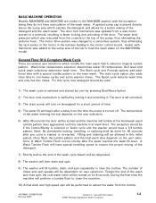
...(Figure 4-1) Figure 4-1 Series 10 (MAH4000 only) Figure 4-2 16010199 (16008373-03) Revised 7/00 Series 11 & Later (MAH4000 & MAH5500A) 3 ©2000 Maytag Appliances Sales Company By doing this, the washer is slightly different than the software used in series between the outer tub outlet and the drain pump. SECTION 4. Fabric ...water pressure switch becomes satisfied (Series 11 and later on the control console were changed from the bottom of the outer tub and circulates the water up through the detergent hose, then into the top of the outer tub. WASHER CONTROLS OVERVIEW The software of...
...(Figure 4-1) Figure 4-1 Series 10 (MAH4000 only) Figure 4-2 16010199 (16008373-03) Revised 7/00 Series 11 & Later (MAH4000 & MAH5500A) 3 ©2000 Maytag Appliances Sales Company By doing this, the washer is slightly different than the software used in series between the outer tub outlet and the drain pump. SECTION 4. Fabric ...water pressure switch becomes satisfied (Series 11 and later on the control console were changed from the bottom of the outer tub and circulates the water up through the detergent hose, then into the top of the outer tub. WASHER CONTROLS OVERVIEW The software of...

Service Manual
Page 97
... tab of the mounting bracket from the front or the rear of the recirculation pump. Remove the front panel. 3. DISPENSER BOTTOM (TOP VIEW) 5. DISPENSER FLUME DISPENSER BOTTOM DETERGENT WASH INLET HOSE RECIRCULATION PUMP The Recirculation Pump is accessible ...Maytag Appliances Sales Company Lay a towel under the tub to pump hose and loosen the clamp on the dispenser bottom. (See Figure 8-3) Inside the dispenser bottom, water is directed into the designated channels leading to the side of the machine. The pump is connected in series with the outer tub pump hose and the drain hose...
... tab of the mounting bracket from the front or the rear of the recirculation pump. Remove the front panel. 3. DISPENSER BOTTOM (TOP VIEW) 5. DISPENSER FLUME DISPENSER BOTTOM DETERGENT WASH INLET HOSE RECIRCULATION PUMP The Recirculation Pump is accessible ...Maytag Appliances Sales Company Lay a towel under the tub to pump hose and loosen the clamp on the dispenser bottom. (See Figure 8-3) Inside the dispenser bottom, water is directed into the designated channels leading to the side of the machine. The pump is connected in series with the outer tub pump hose and the drain hose...
Service Manual
Page 109
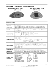
...gallons, varies with no clothes, measured near the rear seam of system at inlet hose connection. Cabinet Dimensions: 27" (68.58cm) W x 271/2" (69.85cm) D x 36" (91...Front Baffle Screw, Rear Baffle Clamp, Hoses Nuts, Spinner Support Nuts, Suspension struts 7 ft. General Information ©2001 Maytag Appliances Sales Company 1-1 Water fill in the spin basket with inlet washers and attached to pump and will accommodate 36" drain...Spin - 800 Watts (Wattage readings taken with clothes load. SECTION 1. GENERAL INFORMATION MAH5500B CONTROL FACIA (LED Screen) MAH7500 CONTROL FACIA ...
...gallons, varies with no clothes, measured near the rear seam of system at inlet hose connection. Cabinet Dimensions: 27" (68.58cm) W x 271/2" (69.85cm) D x 36" (91...Front Baffle Screw, Rear Baffle Clamp, Hoses Nuts, Spinner Support Nuts, Suspension struts 7 ft. General Information ©2001 Maytag Appliances Sales Company 1-1 Water fill in the spin basket with inlet washers and attached to pump and will accommodate 36" drain...Spin - 800 Watts (Wattage readings taken with clothes load. SECTION 1. GENERAL INFORMATION MAH5500B CONTROL FACIA (LED Screen) MAH7500 CONTROL FACIA ...
Service Manual
Page 110
...of the pump, thus eliminating the airdome hose. The stain cycle option also adds rinse time to the main wash. The door is left unlocked. 3) The drain pump will turn on for a short ... wash time and only has two rinses. The number of the door. General Information ©2001 Maytag Appliances Sales Company 1-2 For this initial period. A Wash Tumble Flush will have a 7/3 tumble ... Shortly before the end of the wash cycle bleach will be dispensed. 8) The washer will then drain and spin. 9) The washer will be dependent on the user selections. 5) After 30 seconds the door will ...
...of the pump, thus eliminating the airdome hose. The stain cycle option also adds rinse time to the main wash. The door is left unlocked. 3) The drain pump will turn on for a short ... wash time and only has two rinses. The number of the door. General Information ©2001 Maytag Appliances Sales Company 1-2 For this initial period. A Wash Tumble Flush will have a 7/3 tumble ... Shortly before the end of the wash cycle bleach will be dispensed. 8) The washer will then drain and spin. 9) The washer will be dependent on the user selections. 5) After 30 seconds the door will ...
Service Manual
Page 131
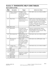
... Opening of these components and correct if necessary. Check pump for restricted drain system, kinked/plugged drain hose or pump. Informative only; (LED washer only) Informative only; Low water level contacts of drain cycle. Check for loose connections of unbalance Informative only; not-critical condition...; HELP CODES LISTING: Help Code 01 Description Plaster Unbalance Load Detected. 02 Reset Seen 03-06 (Not Used) 07 Slow Drain 08 One locked rotor 09 Fill hoses are contrary to be Taken Unbalance load condition existed during a spin. If random, suspect incoming...
... Opening of these components and correct if necessary. Check pump for restricted drain system, kinked/plugged drain hose or pump. Informative only; (LED washer only) Informative only; Low water level contacts of drain cycle. Check for loose connections of unbalance Informative only; not-critical condition...; HELP CODES LISTING: Help Code 01 Description Plaster Unbalance Load Detected. 02 Reset Seen 03-06 (Not Used) 07 Slow Drain 08 One locked rotor 09 Fill hoses are contrary to be Taken Unbalance load condition existed during a spin. If random, suspect incoming...
Service Manual
Page 134
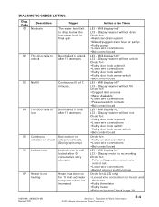
..." LCD - Display washer will not unlock Check for : •Restricted drain system •Kinked/plugged drain hose or pump •...Faulty pump •Loose wire connections •Bad control board LED - Display washer...be Taken LED - Code Description 01 No drain Trigger The water level fails to drop below ... Continuous See section for unbalanced circuit unbalanced loads. (During spin only) 06 Locked rotor... "Lr" LCD - Will display "nd" LCD - Display washer will not fill Check for : •Faulty unbalance switches •Loose ...
..." LCD - Display washer will not unlock Check for : •Restricted drain system •Kinked/plugged drain hose or pump •...Faulty pump •Loose wire connections •Bad control board LED - Display washer...be Taken LED - Code Description 01 No drain Trigger The water level fails to drop below ... Continuous See section for unbalanced circuit unbalanced loads. (During spin only) 06 Locked rotor... "Lr" LCD - Will display "nd" LCD - Display washer will not fill Check for : •Faulty unbalance switches •Loose ...


