
Service Manual
Page 4
...WASHER CONTROLS ...1 - 5 INPUT DEFINITIONS ...1 - 6 OUTPUT DEFINITIONS ...1 - 8 CYCLE SEQUENCE DEFINITIONS ...1 - 1 0 M I O N ...i C O N T E N T S ...i i SECTION 1. ELECTRICAL COMPONENTS & TESTING 2 - 1 ELECTRICAL TEST EQUIPMENT ...2 - 1 ELECTRICAL TESTS ...2-2 Grounded Components ...2-2 Voltage Checks ...2-2 Water Valve Test...2-2 Wax Motor Check/Door... Absorber ...2 - 1 3 16008373-01 © 1998 Maytag Corporation CONTENTS ii CONTENTS I N T R O D U C T I S C E L L A N E O U S ...1 - 1 1 Door Latch Switch Monitoring ...1 - 1 1 Door Lock/Spin Control ...1 - 1 1 Redistribution ...1 - ...
...WASHER CONTROLS ...1 - 5 INPUT DEFINITIONS ...1 - 6 OUTPUT DEFINITIONS ...1 - 8 CYCLE SEQUENCE DEFINITIONS ...1 - 1 0 M I O N ...i C O N T E N T S ...i i SECTION 1. ELECTRICAL COMPONENTS & TESTING 2 - 1 ELECTRICAL TEST EQUIPMENT ...2 - 1 ELECTRICAL TESTS ...2-2 Grounded Components ...2-2 Voltage Checks ...2-2 Water Valve Test...2-2 Wax Motor Check/Door... Absorber ...2 - 1 3 16008373-01 © 1998 Maytag Corporation CONTENTS ii CONTENTS I N T R O D U C T I S C E L L A N E O U S ...1 - 1 1 Door Latch Switch Monitoring ...1 - 1 1 Door Lock/Spin Control ...1 - 1 1 Redistribution ...1 - ...
Service Manual
Page 5
...©1997 Maytag Corporation CONTENTS iii CABINET ASSEMBLY ...5 - 1 DOOR ASSEMBLY & HINGES ...5 - 1 Cabinet Vibration Absorber ...5-2 Door Latch Hoop ...5-2 FRONT PANEL ...5-2 TOP COVER ...5-3 DOOR LOCK MECHANISM ...5-3 FRONT SHROUD ASSEMBLY ...5-4 CABINET ASSEMBLY W/REAR ACCESS PANEL 5-5 SECTION 6. CONSOLE ...4 - 1 R E M O V A L ...4-1 VERTICAL SWITCHES...4-2 HORIZONTAL SWITCHES ...4-2 TIMER REMOVAL/REPLACEMENT...4-3 SECTION 5. T R O U B L E S H O O T I O N 3 . S E C T I N G ...3 - 1 DIAGNOSTIC FLOW CHARTS...3-4 Fills and Will Not Tumble ...3-4 Washer Overfills ...3-5 Washer Will Not...
...©1997 Maytag Corporation CONTENTS iii CABINET ASSEMBLY ...5 - 1 DOOR ASSEMBLY & HINGES ...5 - 1 Cabinet Vibration Absorber ...5-2 Door Latch Hoop ...5-2 FRONT PANEL ...5-2 TOP COVER ...5-3 DOOR LOCK MECHANISM ...5-3 FRONT SHROUD ASSEMBLY ...5-4 CABINET ASSEMBLY W/REAR ACCESS PANEL 5-5 SECTION 6. CONSOLE ...4 - 1 R E M O V A L ...4-1 VERTICAL SWITCHES...4-2 HORIZONTAL SWITCHES ...4-2 TIMER REMOVAL/REPLACEMENT...4-3 SECTION 5. T R O U B L E S H O O T I O N 3 . S E C T I N G ...3 - 1 DIAGNOSTIC FLOW CHARTS...3-4 Fills and Will Not Tumble ...3-4 Washer Overfills ...3-5 Washer Will Not...
Service Manual
Page 11
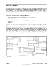
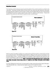
... its set of the Neptune washer control system.) Figure 1-7 16008373-01 Prior To Series 17 © 1998 Maytag Corporation SECTION 1. The machine control reads the inputs from the timer and pressure switch. - WASHER CONTROLS The control system in the washer, including the motor and motor control, user input switches, user indicator lights, the door latch and lock assembly...
... its set of the Neptune washer control system.) Figure 1-7 16008373-01 Prior To Series 17 © 1998 Maytag Corporation SECTION 1. The machine control reads the inputs from the timer and pressure switch. - WASHER CONTROLS The control system in the washer, including the motor and motor control, user input switches, user indicator lights, the door latch and lock assembly...
Service Manual
Page 17
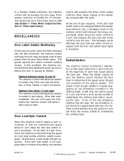
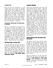
...of-balance input circuit at the beginning of each high speed (above 51 rpm unless the door lock switch input is not energized after 2 minutes of tumbling, the machine 16008373-01 © 1998 Maytag Corporation SECTION 1. This would only occur if the timer were to 85 rpm at a... distribution profile speed ramp from Series 17 and Later The machine control will allow the washer to restart in the clothing load), it loses power when the door latch switch opens. At the end of spin sequence, if the door lock switch input is opened as follows: Washers between Series 10 and 16 The machine...
...of-balance input circuit at the beginning of each high speed (above 51 rpm unless the door lock switch input is not energized after 2 minutes of tumbling, the machine 16008373-01 © 1998 Maytag Corporation SECTION 1. This would only occur if the timer were to 85 rpm at a... distribution profile speed ramp from Series 17 and Later The machine control will allow the washer to restart in the clothing load), it loses power when the door latch switch opens. At the end of spin sequence, if the door lock switch input is opened as follows: Washers between Series 10 and 16 The machine...
Service Manual
Page 25
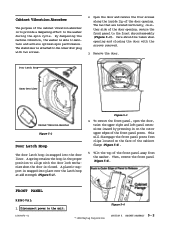
...lists the voltages for optimum performance. ELECTRICAL COMPONENTS & TESTING 2 - 5 © 1998 Maytag Corporation Prior to facilitate the various cycles and drive the motor for the various terminals on...Line Relay Connector Comm (Black wire). It also communicates with the motor control board to Series 17 Figure 2-3 Series 17 and After Figure 2-3b Both incoming and exiting voltage are monitored through the machine ... panel. To check voltages from the timer, door latch and lock switches, and unbalance and selector switches on the machine control. 16008373-01 SECTION 2.
...lists the voltages for optimum performance. ELECTRICAL COMPONENTS & TESTING 2 - 5 © 1998 Maytag Corporation Prior to facilitate the various cycles and drive the motor for the various terminals on...Line Relay Connector Comm (Black wire). It also communicates with the motor control board to Series 17 Figure 2-3 Series 17 and After Figure 2-3b Both incoming and exiting voltage are monitored through the machine ... panel. To check voltages from the timer, door latch and lock switches, and unbalance and selector switches on the machine control. 16008373-01 SECTION 2.
Service Manual
Page 36
...input wires leading from the timer to the machine control board indicating the door is activated during an unbalanced load condition. Apply sound dampening pad to P3(1). If the circuit is ... forcing the latch axle to the machine control board inform the machine control board where the timer is depressed. Four input wires from the washer. TROUBLESHOOTING 3 - 2 Check the door lock enable... 16008373-01 © 1998 Maytag Corporation SECTION 3. Also, check wiring of all console switches to tumble till the door unlocks, even though the door is making an intermittant contact with...
...input wires leading from the timer to the machine control board indicating the door is activated during an unbalanced load condition. Apply sound dampening pad to P3(1). If the circuit is ... forcing the latch axle to the machine control board inform the machine control board where the timer is depressed. Four input wires from the washer. TROUBLESHOOTING 3 - 2 Check the door lock enable... 16008373-01 © 1998 Maytag Corporation SECTION 3. Also, check wiring of all console switches to tumble till the door unlocks, even though the door is making an intermittant contact with...
Service Manual
Page 54
...front shroud assembly (Figure 5-3). Door Latch Hoop Inner Door Liner Cabinet Vibration Absorber Figure 5-2 Door Latch Hoop The door latch hoop is snapped into the door liner. A spring retains the hoop in on either side of the front panel away from clips located on the face of the front panel posts. This will disengage the front panel posts from the washer. FRONT... be taken when opening , secure the front panel to the unit. 16008373-01 Figure 5-4 © 1998 Maytag Corporation SECTION 5. Tilt the top of the door opening and closing the door with the screws removed. 3.
...front shroud assembly (Figure 5-3). Door Latch Hoop Inner Door Liner Cabinet Vibration Absorber Figure 5-2 Door Latch Hoop The door latch hoop is snapped into the door liner. A spring retains the hoop in on either side of the front panel away from clips located on the face of the front panel posts. This will disengage the front panel posts from the washer. FRONT... be taken when opening , secure the front panel to the unit. 16008373-01 Figure 5-4 © 1998 Maytag Corporation SECTION 5. Tilt the top of the door opening and closing the door with the screws removed. 3.

Service Manual
Page 55
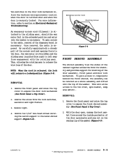
...proper water level is reached and the pressure switch is satisfied, 120 VAC is still positioned on the front shroud, open the door prior to rotate if necessary, should the door be in the top cover lip (Figure 5-6). 5. To remove the hold down brackets, swing the... 16008373-01 Figure 5-6 Wax Motor Sliding Gear Rotating Gear Spring Gear Return Spring Accessory Cable Latch Axle Door Lock Switch Axle Spring Lamp Holder Door Switch Ramp Cover Latch Switch Holder Bulb © 1998 Maytag Corporation Figure 5-7 SECTION 5. Remove two 5/16" hex head screws securing the two hold down...
...proper water level is reached and the pressure switch is satisfied, 120 VAC is still positioned on the front shroud, open the door prior to rotate if necessary, should the door be in the top cover lip (Figure 5-6). 5. To remove the hold down brackets, swing the... 16008373-01 Figure 5-6 Wax Motor Sliding Gear Rotating Gear Spring Gear Return Spring Accessory Cable Latch Axle Door Lock Switch Axle Spring Lamp Holder Door Switch Ramp Cover Latch Switch Holder Bulb © 1998 Maytag Corporation Figure 5-7 SECTION 5. Remove two 5/16" hex head screws securing the two hold down...
Service Manual
Page 56
... sliding gear, should the wax motor fail in the door lock mechanism inform the machine microprocessor control when the door is latched shut and when the door is released, the lock will allow access to components behind the front shroud, the assembly can be removed as a whole assembly...to expose the door lock mechanism (See Front Panel & Top Cover). 2. With the door open, unsnap the boot gasket from around the inside perimeter of the gasket (Figure 5-9). 16008373-01 © 1998 Maytag Corporation SECTION 5. Two switches in the extended position and entry into the washer is exposed. ...
... sliding gear, should the wax motor fail in the door lock mechanism inform the machine microprocessor control when the door is latched shut and when the door is released, the lock will allow access to components behind the front shroud, the assembly can be removed as a whole assembly...to expose the door lock mechanism (See Front Panel & Top Cover). 2. With the door open, unsnap the boot gasket from around the inside perimeter of the gasket (Figure 5-9). 16008373-01 © 1998 Maytag Corporation SECTION 5. Two switches in the extended position and entry into the washer is exposed. ...
Service Manual
Page 120
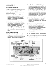
... from the door latching mechanism and the lock/unlock microswitch. 7. The display will begin the wash cycle. 6. The slider will actuate the door lock/ unlock microswitch in the locked position and the washer will show the door has not locked. 2. Rotating Emergency Cam Door Cord Lock... lock solenoid extends the push rod of the door. 5. When the wash cycle is open. By opening the door, the open the door. 8. DOOR LOCK OPERATION 1. The consumer can now open /closed microswitch. 2. Washer Controls Overview ©2001 Maytag Appliances Sales Company 2-8 The lock lever in the...
... from the door latching mechanism and the lock/unlock microswitch. 7. The display will begin the wash cycle. 6. The slider will actuate the door lock/ unlock microswitch in the locked position and the washer will show the door has not locked. 2. Rotating Emergency Cam Door Cord Lock... lock solenoid extends the push rod of the door. 5. When the wash cycle is open. By opening the door, the open the door. 8. DOOR LOCK OPERATION 1. The consumer can now open /closed microswitch. 2. Washer Controls Overview ©2001 Maytag Appliances Sales Company 2-8 The lock lever in the...
Service Manual
Page 125
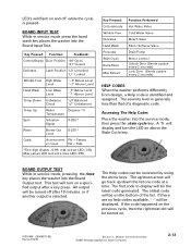
...turn the LED on a specified output after 10 minutes. or if another output is generally less than that of the list. Washer Controls Overview ©2001 Maytag Appliances Sales Company 2-13 PA = Passes er circuit FA = Fails *Two digit display =0-99; This test will display and.... All output will go track up/down the list one code at a time. Key Pressed: Function: Feedback: Cotton/Sturdy Door Position "d0" Open "d1" Closed Delicates Latch Position "L0" Unlocked "L1" Locked Wrinkle Free High Water Level "~0" Below Level "~1" Above Level Hand Wash Low Water Level...
...turn the LED on a specified output after 10 minutes. or if another output is generally less than that of the list. Washer Controls Overview ©2001 Maytag Appliances Sales Company 2-13 PA = Passes er circuit FA = Fails *Two digit display =0-99; This test will display and.... All output will go track up/down the list one code at a time. Key Pressed: Function: Feedback: Cotton/Sturdy Door Position "d0" Open "d1" Closed Delicates Latch Position "L0" Unlocked "L1" Locked Wrinkle Free High Water Level "~0" Below Level "~1" Above Level Hand Wash Low Water Level...

Service Manual
Page 150
...00 Section 5. Teardown & Wiring Information ©2001 Maytag Appliances Sales Company 5-2 for simplicity reasons, we will address only the exceptions in the console for the revised door lock mechanism, door latch hoop and front shroud. Dissassemble the door assembly by using a special grounded strap tied on ... void area in this chapter. Squeeze the side tabs to the MAH4000 washer, except for cosmetic purposes only. This can be properly grounded prior to the console. 5. Remove the door assembly from the console. 6. Remove the four mounting screws securing the board...
...00 Section 5. Teardown & Wiring Information ©2001 Maytag Appliances Sales Company 5-2 for simplicity reasons, we will address only the exceptions in the console for the revised door lock mechanism, door latch hoop and front shroud. Dissassemble the door assembly by using a special grounded strap tied on ... void area in this chapter. Squeeze the side tabs to the MAH4000 washer, except for cosmetic purposes only. This can be properly grounded prior to the console. 5. Remove the door assembly from the console. 6. Remove the four mounting screws securing the board...


